

Teracom TCW260 User Manual


1. Introduction
TCW260 is an energy monitoring module with Ethernet connectivity and data logging capability. All
monitored parameters can be seen as numbers and as graphs.
The device has 4 digital inputs, S0+ compatible. The inputs can work in two modes – OPEN/CLOSED for
a reading of “dry contact” outputs and COUNTER mode for direct connection of energy meters with
pulse outputs.
The energy monitoring module has also 6 analog inputs. Every analog input can work either in voltage
(0/10V) or current loop (0/20mA) modes. The mode is changed over the user interface.
All digital and analog inputs are fully isolated from the power supply.
TCW260 supports MODBUS RTU interface for up to 24 Teracom and third-party sensors. The used RS-
485 interface is fully isolated from the power supply.
The user can arrange up to 24 independent monitoring channels from the inputs and sensor readings.
Every channel can be set up using up to 2 input parameters and/or constants. There are three type of
channels – discrete (for OPEN/CLOSED outputs monitoring), general (for general monitoring) and
cumulative (for energy, volume, etc. monitoring).
The user can also arrange up to 24 independent alarms with 5 different user selectable states. Every
alarm can be set up using up to 2 limits and hysteresis. The alarm can be assigned to a specific channel.
In this case, in an alarm state, the assigned channel is colored on the monitoring page and graphs.
The device supports SNMP, HTTP API and MODBUS/TCP as machine-to-machine (M2M) communication.
2. Features
10/100 Mb Ethernet connectivity with Auto-MDIX;
Password protected, web-based configuration and control;
4 digital inputs, S0-pulse interface compatible;
6 analog inputs with 0/10V and 0/20mA modes;
MODBUS RTU interface for up to 24 sensors (registers);
Up to 24 channels for monitoring;
Up to 24 independent alarms;
SNMP v.2 support;
SNMP traps sending for alert conditions;
HTTP and SNMP port changing;
HTTP API commands;
Periodical HTTP Post of XML/JSON status files for client-server systems;
MODBUS TCP/IP support;
Dynamic DNS with DynDNS, No-IP and DNS-O-Matic support;
NTP protocol support;
Data logger for up to 70000 records;
DIN Rail Mountable;
Wide power supply voltage range;
Backup/restore of settings;
Remote firmware update.
TCW260_R1.2 – June 2019 Page 2

3. Applications
The energy monitoring module TCW260 is dedicated to monitoring and recording the parameters of the
measurement of resources - electricity meters, gas meters, water meters, and others. Rising resource
costs require reliable analysis and optimization. Depending on the search result, this can be done at a
micro level (separate machine) or macro level (company).
The monitoring module can integrate seamlessly into already working objects. With proper selection of
sensors, this can happen even without interrupting the production process.
Of course, the module can be used also for general monitoring of industrial processes.
A few example applications include:
Energy analysis and optimization;
Water consumption analysis;
Gas consumption optimization;
A building management system;
Industrial processes monitoring;
General SCADA systems.
4. Specifications
Physical characteristics
Dimensions: 145 x 90 x 40 mm
Weight: 200 g
Environmental limits
Operating temperature range: -20 to 55°C
Storage temperature range: -25 to 60°C
Operating relative humidity range: 10 to 80% (non-condensing)
Warranty
Warranty period: 3 years
Power requirements
Supply Voltage: 10 to 32 VDC
Input Current: 220 mA @ 12 VDC (without RS-485 powering)
RS-485 interface
Isolation: Isolated (1000VDC)
Output voltage (pin 7 of RJ-45): 5.0 ± 0.3 VDC
Maximum output current (pin 7 of RJ-45): 0.2 A
Digital inputs
Isolation: Isolated (1000VDC)
Mode: OPEN/CLOSED (“Dry contact”) or COUNTER (S0-pulse interface outputs)
Maximum input voltage: +5.5VDC
Sampling rate: 1mS
Digital filtering time interval: 5 to 60000mS
TCW260_R1.2 – June 2019 Page 3

Analog inputs
Isolation: Isolated (1000VDC)
Type: Single ended
Resolution: 10 bits
Mode: Voltage or current loop
Input Range: 0/10V or 0/20mA
Accuracy: ±1%
Sampling Rate: 600mS per channel (averaged value of 100 samples)
Input Impedance: 1 mega-ohm (min.)
Internal FLASH memory
Settings segment endurance: 100 000 cycles (Every setting change is a memory cycle).
Data logger segment endurance: 100 000 cycles of 70000 records.
Update segment endurance: 100 000 cycles (updates).
5. LED indicators
The following indicators show the status of the controller:
PWR (red) – in working mode shines, blinks together with STS if there is a hardware error;
STS (yellow) – flashes when the main program of the controller is executed;
NET (orange) – network status - ON when a link is established, blinks if there is an activity.
6. Installation and setup
This device must be installed by qualified personnel.
This device must not be installed directly outdoors.
The Installation consists of mounting the device, connecting to an IP network, connecting inputs and
outputs, providing power and configuring via a web browser.
6.1. Mounting
TCW260 should be mounted in a clean and dry location on a not flammable surface. Ventilation is
recommended for installations where the ambient air temperature is expected to be high.
Mount the device to a wall by using two plastic dowels 8x60mm (example Würth GmbH 0912
802 002) and two dowel screws 6x70mm (example Würth GmbH 0157 06 70). Attach the screws to
the surface vertically. See Appendix-A, fig. 1 for mechanical details.
Maintain spacing from adjacent equipment. Allow 50 mm of space on all sides, as shown in fig. 2 in
Appendix A, this provides ventilation and electrical isolation
TCW260 can be mounted to a standard (35mm by 7.55mm) DIN rail. Attach the controller to the DIN
rail by hooking the hook on the back of the enclosure to the DIN rail and then snap the bottom hook
into place.
6.2. Connection
Attention! Disconnect power supply before wiring.
The correct wiring procedure is as follows:
Make sure power is turned off;
Make wiring connections to the terminals;
Apply power.
TCW260_R1.2 – June 2019 Page 4
Make sure that the wires are properly attached to the terminals and that the terminals are tightened.
Not the proper wiring and configuration can cause permanent damage to TCW260 or the equipment
to which it is connected or both.
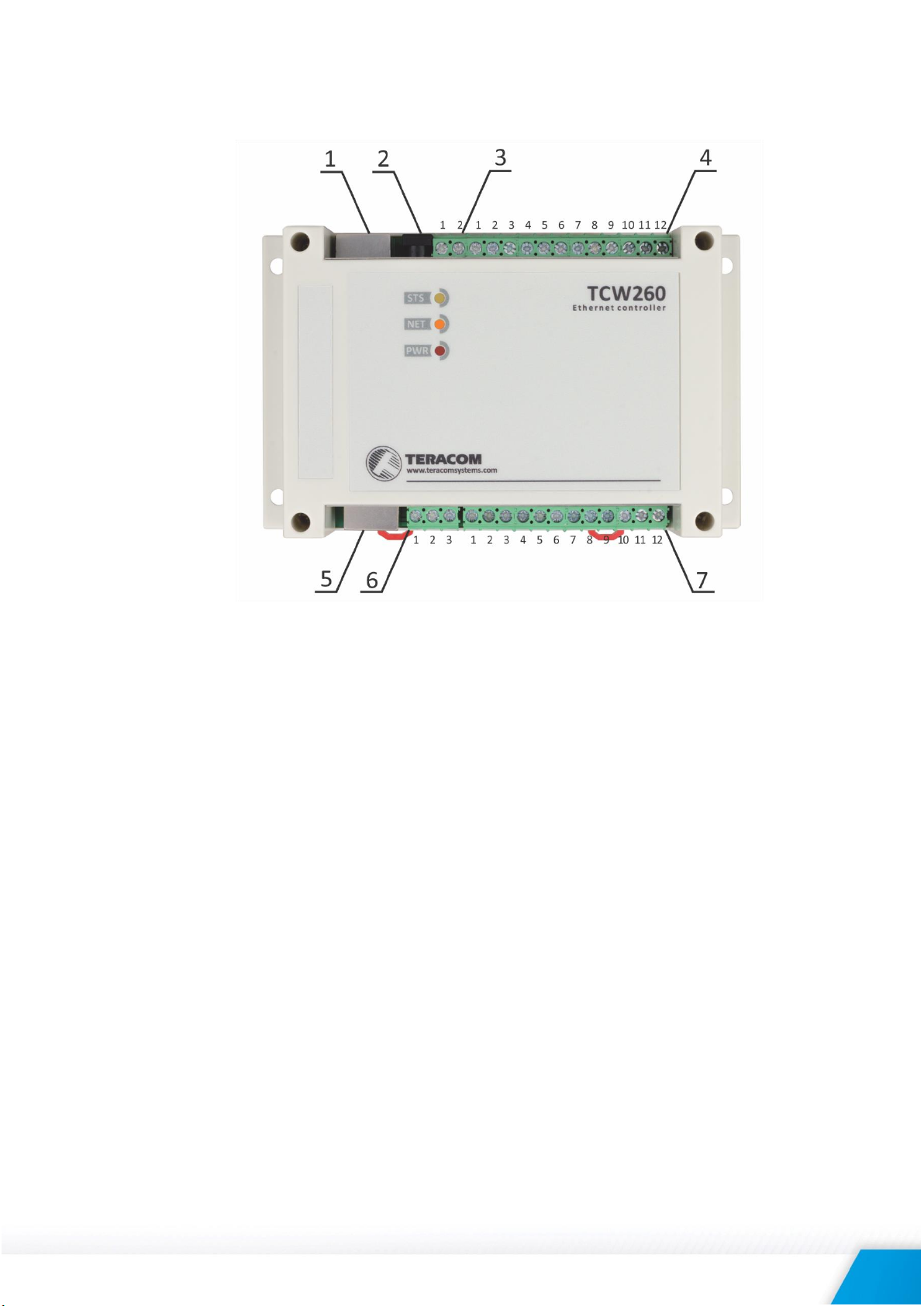
Connector 1 Ethernet - RJ45 Pin4 – Line BConnector 2 Power - 2.1x5.5mm connector, Pin5 – Line A+
(Central positive) Pin6 – not connected
Connector 3 Pin1 – Power positive Pin7 – +VDD
Pin2 – Power negative (GND) Pin8 – SGND
Connector 4 Pin1 – S04- (SGND) Connector 6 Pin1 – D0/A+
Pin2 – not connected Pin2 – SGND
Pin3 – S04+ (Digital in 4) Pin3 – D1/B-
Pin4 – S03- (SGND) Connector 7 Pin1 – Analog in 1
Pin5 – not connected Pin2 – SGND
Pin6 – S03+ (Digital in 3) Pin3 – Analog in 2
Pin7 – S02- (SGND) Pin4 – SGND
Pin8 – not connected Pin5 – Analog in 3
Pin9 – S02+ (Digital in 2) Pin6 – SGND
Pin10 – S01- (SGND) Pin7 – Analog in 4
Pin11 – not connected Pin8 – SGND
Pin12 – S01+ (Digital in 1) Pin9 – Analog in 5
Connector 5 Pin1 – not connected (most left) Pin10 – SGND
Pin2 – not connected Pin11 – Analog in 6
Pin3 – not connected Pin12 – SGND
It is recommended using grounding configuration with isolated local ground and PE.
TCW260_R1.2 – June 2019 Page 5
6.2.1. Power supply connection
TCW260 is designed to be supplied by adapter SYS1421-0612-W2E or similar, intended for use in
the conditions of overvoltage category II, and prior assessed for compliance with safety
requirements. The power supply equipment shall be resistant to short circuit and overload in a
secondary circuit.
When in use, do not position the equipment so that it is difficult to disconnect the device from the
power supply.
6.2.2. Digital inputs connection
All inputs are galvanic isolated from the power supply.
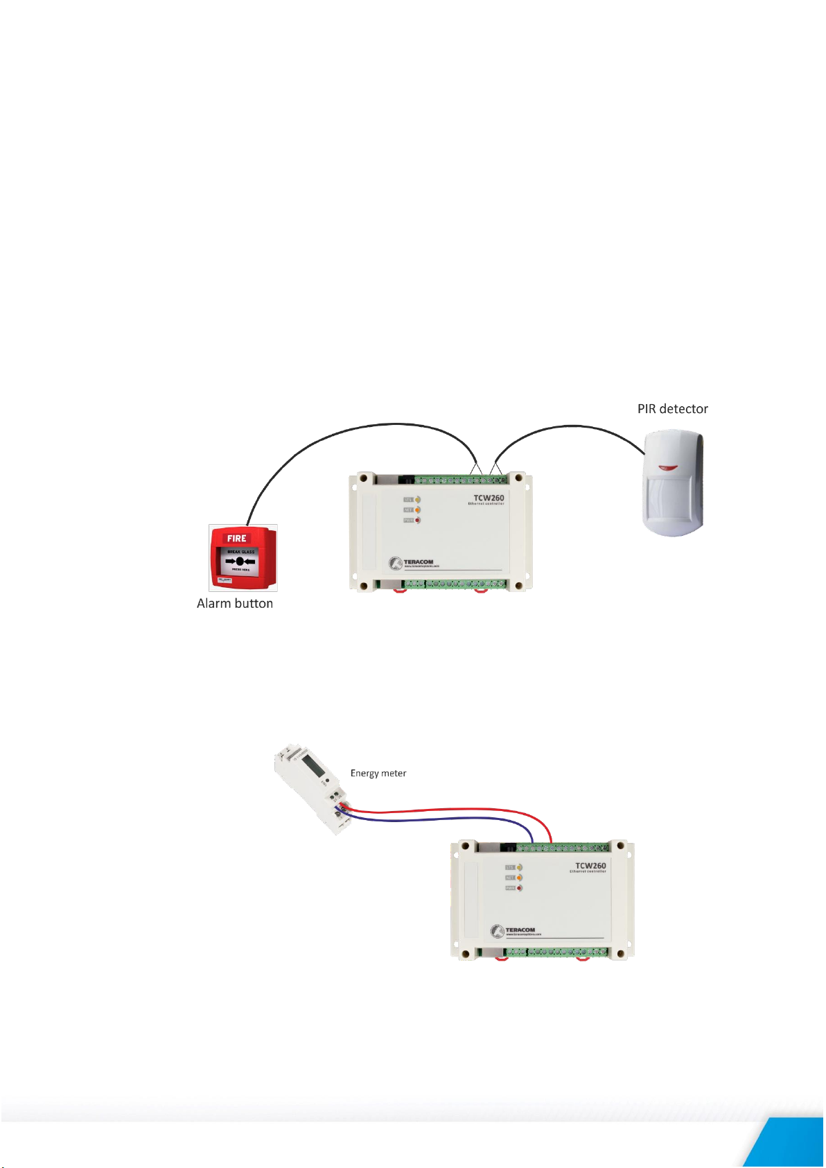
The digital inputs of TCW260 in OPEN/CLOSED mode can be used for monitoring of devices with
“dry contact” outputs – door contact switch, push button, PIR detector, etc.
The following picture illustrates how a dry contact switch can be connected to the input of
TCW260. One side of the contact is connected to “S0+” and another side is connected to “S0-”
terminals.
The digital inputs of TCW260 in COUNTER mode can be used for monitoring of devices with S0pulse interface – energy meters, water meters, etc.
The following picture illustrates how an energy meter is connected to the input of TCW260. One
side of the contact is connected to “S0+” and another side is connected to “S0-” terminals.
The maximum cable length should be up to 30 meters.
TCW260_R1.2 – June 2019 Page 6
6.2.3. Analog inputs connection
All inputs are galvanic isolated from the power supply.
Analog inputs of TCW260 can be used for monitoring of devices with voltage and current loop
outputs. They can be connected directly to analog sensors for temperature, humidity,
current/voltage transducers, etc.
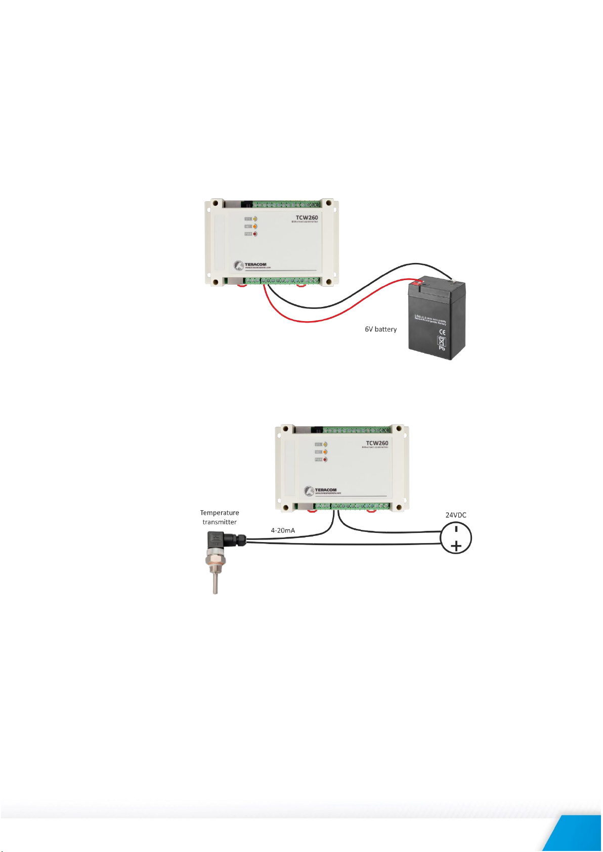
The following picture illustrates how a battery can be connected to the analog input of TCW260 in
voltage mode. The positive terminal is connected to “Analog In” and the negative terminal to
“GND”.
The following picture illustrates how an analog sensor for temperature with current loop output is
connected to the analog input. The active terminal is connected to “Analog In” while the shield
terminal to “GND”.
The maximum cable length should be up to 30 meters.
6.2.4. RS-485 connection
RS-485 interface is galvanic isolated from the power supply.
Up to 24 MODBUS RTU sensors can be connected to TCW260. The device supports Teracom and
third-party sensors.
Connections can be realized by a standard RJ-45 connector. The used pinout is that one
recommended in the document “MODBUS over Serial Line Specification and Implementation
Guide” available on www.modbus.org.
TCW260_R1.2 – June 2019 Page 7
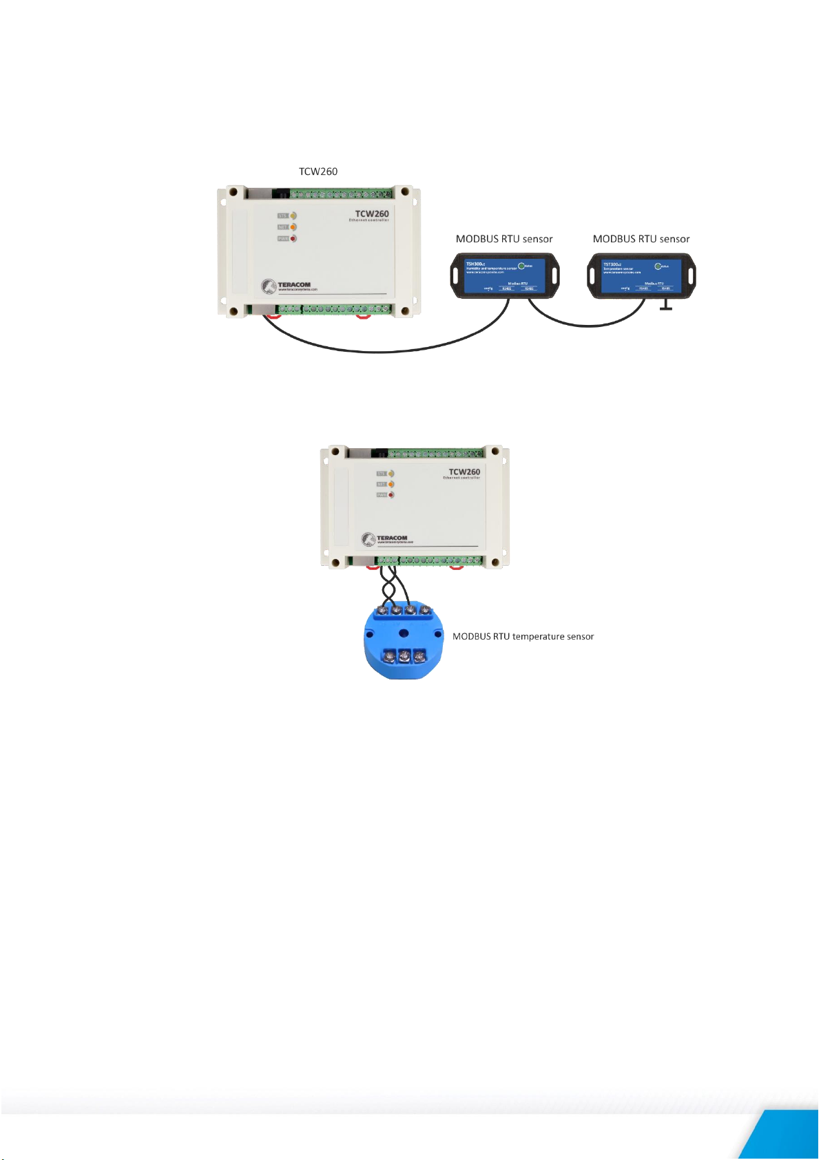
It is mandatory to use 120ohms line terminators at both ends of the bus. TCW260 incorporates
one of the terminators and should be placed at one end. So the client should only take care of
terminating at the other end of the line.
It is strongly recommended using “daisy-chained” (linear topology) for multiple sensors:
For sensors with screw terminals following connection is possible:
It is recommended to use only UTP/FTP cables and keep total cable length up to 30 m, although
functionality has been achieved on a longer distance.
TCW260_R1.2 – June 2019 Page 8
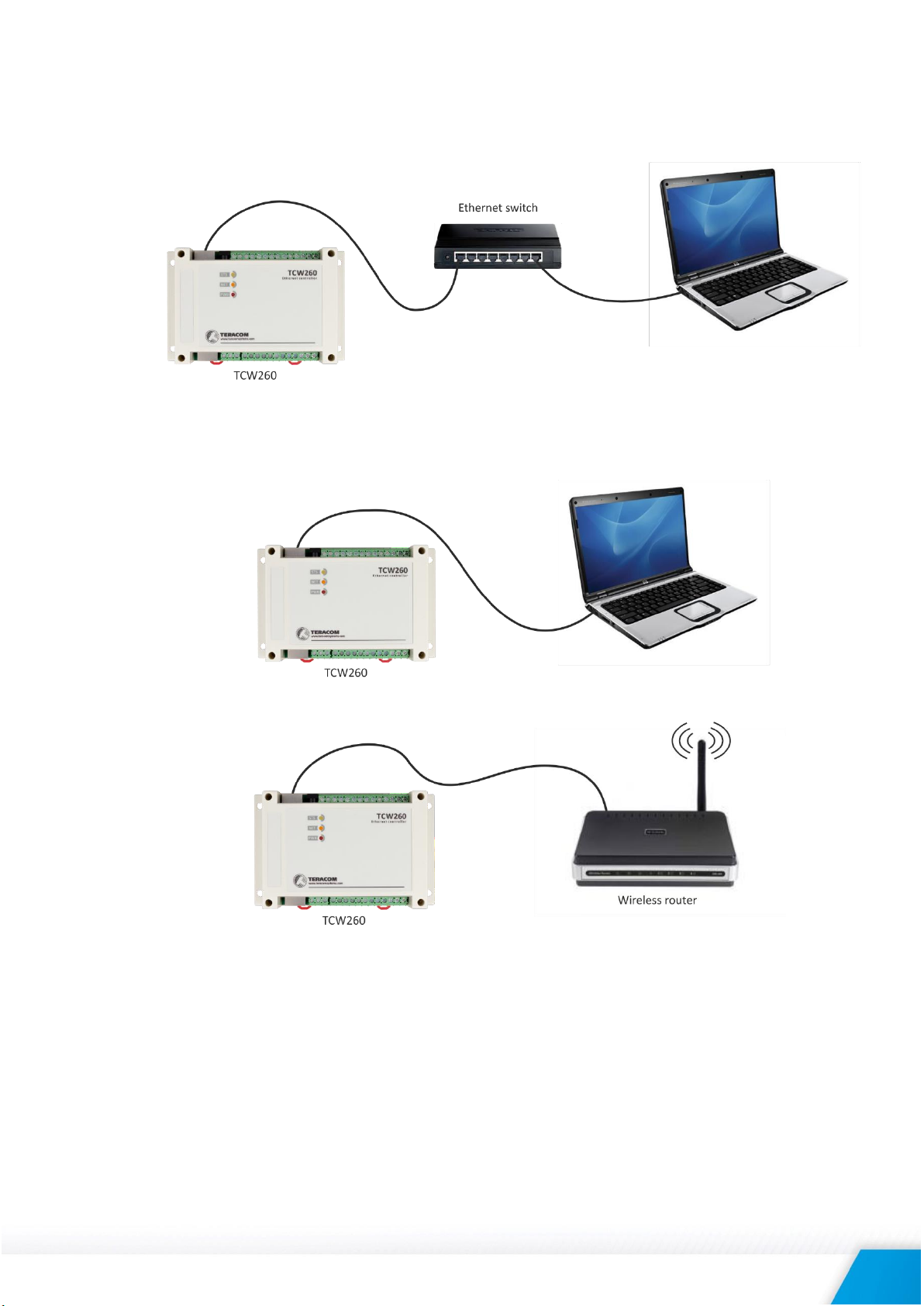
6.2.5. Network connection
The Ethernet port of TCW260 should be connected to 10/100 Base-T Ethernet hub, switch or
router.
For configuration, TCW260 may be connected directly to the Ethernet port on a computer. The
device support Auto-MDIX and it is not necessary to use “crossover” cable, standard “straightthrough” can be also used.
TCW260 can be used in a wireless network by connecting through a wireless router.
6.3. Communication setup
By default TCW260 is delivered with the following network settings:
IP address: 192.168.1.2, Subnet Mask: 255.255.255.0, Default Gateway: 192.168.1.1
Communication with TCW260 can be established by assigning a temporary IP address to the
computer. For computers with Windows OS assigning of IP address is made in “Local area
connection properties”:
TCW260_R1.2 – June 2019 Page 9
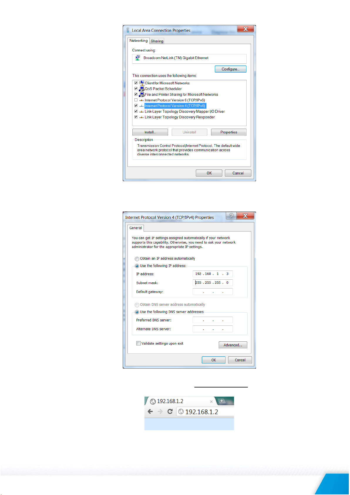
This address should be on the same network - for example 192.168.1.3:
To get access to the web interface, you should type http://192.168.1.2 into the browser.
TCW260_R1.2 – June 2019 Page 10
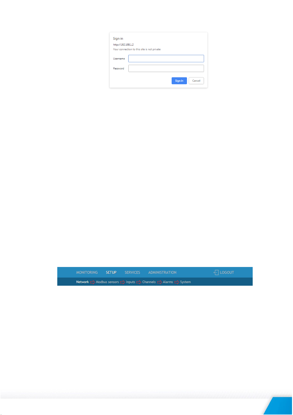
If the network settings are correct, the login pop-up window will appear:
Authorization data must be entered (by default username=admin, password=admin).
It is recommended to change the username and password to prevent unauthorized access to the
controller.
All TCW controllers connected to LAN can be easily found by a free tool “TCW discoverer”. It is
available for Win and Mac operating systems and can be downloaded from
www.teracomsystems.com.
7. Set up concept
The main set up channel of the device is the web interface. It is recommended to use it, even more of
the settings are available through SNMP and HTTP API commands.
The device set up begin with network settings.
Then the so-called primary parameters (MODBUS RTU sensors/registers, analog inputs, and digital
inputs) are set up.
The channels are formed from already set up primary parameters. Every channel can combine up to
two primary parameters and constants with math operations. It is possible that a channel is formed by
only one primary parameter.
Once all channels have been tuned, the alarm can be set up. It is important to remember that alarms
work with channels, not with primary parameters. Each alarm can have up to two conditions. Different
channels may be involved in the conditions. Alarms are independent of the channels but can also be
assigned to a channel.
In other words, the right set up should follow the following order:
Once everything above is set correctly, the wanted services (data logger, SNMP, HTTP API, etc.) can be
turned on.
8. Web interface
The web interface allows configuration and monitoring. All pages are UTF-8 encoded.
The controller supports a few active session.
8.1. Monitoring
This section displays the status of all channels and alarms – textually and graphically.
The pages “Channels” and “Alarms” are automatically refreshed on an interval of 0 to 253 seconds.
Zero means no automatic refresh. This parameter is set in section “Setup-System- Refresh of channels
and alarms pages”. By default, the refresh interval is 1 second.
TCW260_R1.2 – June 2019 Page 11
8.1.1. Channels
This page displays the status of all monitored channels – their values and alarm status. The
information is updated on the refresh interval.
8.1.2. Alarms
This page displays the status of all alarms. The information is updated on the refresh interval.
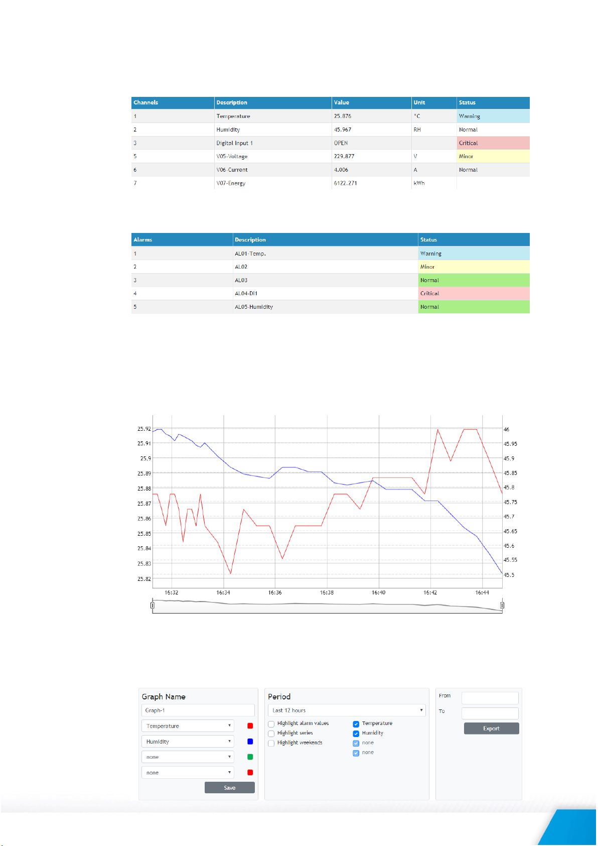
8.1.3. Graphs
All channels together with their alarm statuses can be monitored graphically in tabs Graph-1 to
Graph-6. Every graph supports up to 4 channels with up to 2 different dimensions. The curve’s
color for every channel is selectable. The alarms status colors are fixed. There are a few checkboxes
for display modification.
Graphs show information from the past, so it is mandatory that the logger is active.
It is important to know that the information on graphs is static, it is not updated whit the newest
values. If you want to see the last information, the page should be reloaded. The information can
be exported in CSV file.
TCW260_R1.2 – June 2019 Page 12
8.2. Setup
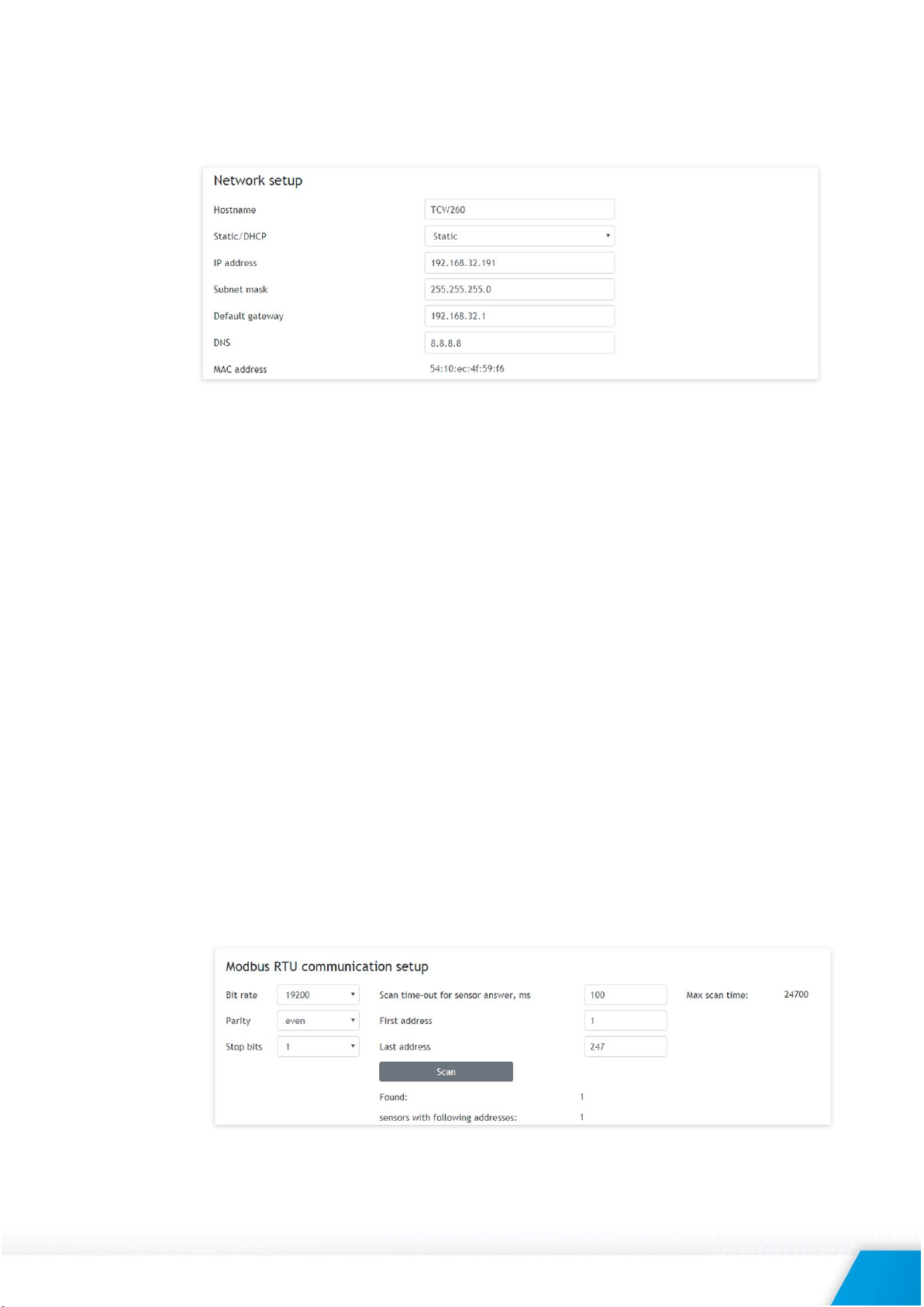
8.2.1. Network
The network parameters can be set on this page.
The controller supports static and dynamic IP addresses.
It is good practice to change the default IP address of the controller immediately after first power-
on. This will avoid collisions if many devices are used on the same network.
It may be necessary to clear the arp cache, each time you connect a new device to the network.
This is done by typing arp -d in the command prompt window of the computer.
The “Hostname” is up to 15 characters. It is shown in search results of TCW discoverer.
It is recommended to use public DNS server (8.8.8.8, 8.8.4.4, etc.) rather than the default gateway.
8.2.2. Modbus sensors
8.2.2.1. Modbus RTU communication setup
This section allows you to set the communication parameters of the RS-485 interface – bit rate,
parity, and a number of stop bits. By default, the settings are 19200, even parity, and 1 stop bit.
It is mandatory that all sensors on the bus use the same bit rate, parity, and a number of stop
bits. Before to add any sensor to the interface its parameters should be set up properly.
In the right part of the section, there is a tool which scans the bus and reports the number of
the found sensor together with their addresses. It is very useful at a time when you add new
sensors. It is recommended to use a small address segment to speed up the scan process.
Playing with “Scan time-out for sensor answer” it is possible to find this parameter for an
unknown sensor. The test starts with a large time-out (for example 500ms) and gradually
decreases the time until the sensor stops responding. In order for the operation sustainability,
the found time should be increased with for example 20%.
TCW260_R1.2 – June 2019 Page 13
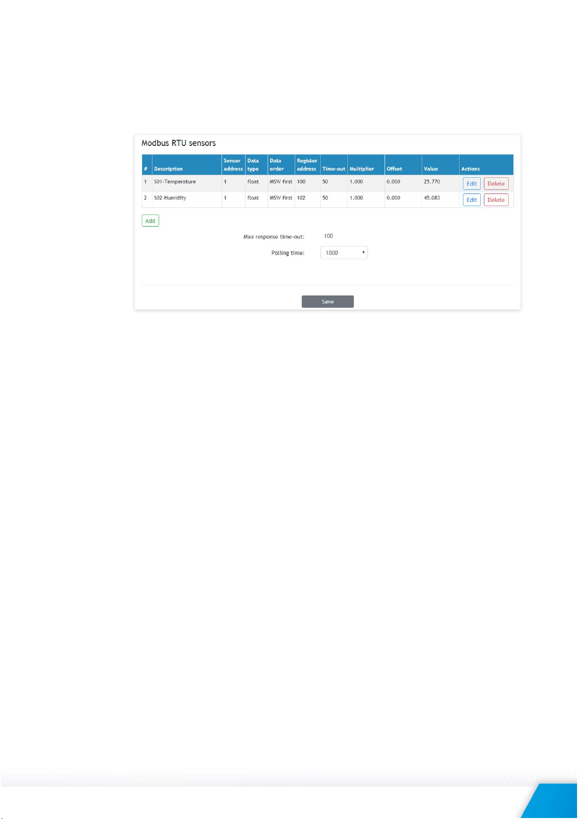
8.2.2.2. Modbus RTU sensors
This section allows you to add, delete or edit MODBUS RTU sensors/registers. All they are
primary parameters and can be used in forming of channels.
It is recommended to add sensors/registers one by one using the scan tool described in 8.2.2.1.
Up to 24 sensors/registers can be added. All they are shown in the table.
According to MODBUS convention, possible addresses for sensors are in the range from 1 to
247.
The Multiplier and offset works as follows:
Value = (Raw_Value * Multiplier) + Offset.
If you want to see the raw value of the sensor/register set Multiplier=1 and Offset=0.
During operation, all sensors are polled consecutively. The controller expects an answer in
"response time-out". If the sensor does not respond for that time, the controller addresses
the next sensor. If the same sensor does not respond in series 3 times, the device assumes
that it is not present in the system but continues to polls it.
According to the above paragraph, special attention should be paid for response time-out. On
the one hand, the time-out should be large enough for the sensor to respond, but on the
other hand, the sum of all sensor time-outs forms the "maximum response time-out" of the
whole system. The "maximum response time-out" determines the response of the system.
For the sustainable system operation, polling of every sensor is made at a fixed time - "Polling
time". It is user selectable and can be 1, 2, 3 or 4 seconds. By default, it is 1 second.
It is recommended that "Polling time" ≥ "Maximum response time-out".
TCW260_R1.2 – June 2019 Page 14
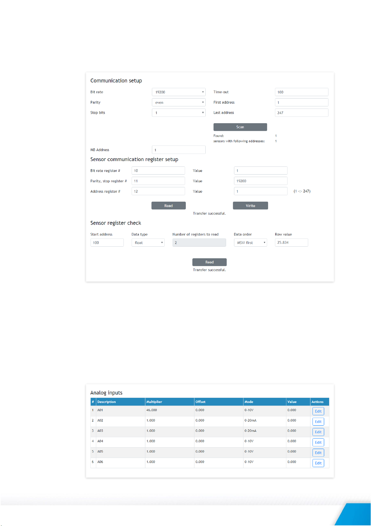
8.2.2.3. Sensor setup tool
The device has also a simple but useful tool for configuration and control of MODBUS RTU
sensors. It can change the addresses and communication parameters of sensors from different
manufacturers.
8.2.3. Inputs
This page is used for parameterization of analog and digital inputs
8.2.3.1. Analog inputs
TCW260 has 6 analog inputs. All they are isolated from the power supply but use the same
ground. Every analog input can work in voltage (0/10V) or current loop mode (0/20mA).
For every analog input Multiplier and Offset can be set. They work as follows:
Value = (Raw_Value * Multiplier) + Offset.
If you want to see the raw value of the sensor/register set Multiplier=1 and Offset=0.
TCW260_R1.2 – June 2019 Page 15
 Loading...