

Teracom TCW241 User Manual


Ethernet I/O module TCW241
1. Introduction
TCW241 is a multi-functional device for monitoring and control in Ethernet-based networks. It has 4
digital inputs, 4 analog inputs and 4 relays with normally open and normally closed contacts.
Ethernet I/O module supports up to eight Teracom 1-Wire sensors for temperature, humidity, CO2,
current, 4/20mA, galvanic isolated analog voltage etc.
The relays can be activated either remotely (WEB, SNMP, HTTP API, MODBUS/TCP, etc.) or locally –
from the status of a monitored parameter (1 Wire sensor, analog voltage, and dry contact).
An XML / JSON file with all monitored parameters can periodically upload on a dedicated server with
HTTP Post. Like answer server can return commands for relay's control. This is a way for building
SCADA system. For every parameter email and SNMP traps for up to 5 recipients can be sent. Alarm
alert also can be sent by HTTP Post with XML/JSON status files.
An embedded real-time clock provides scheduled time control of selected outputs: the tasks can be
either single or with weekly repetition.
2. Features
10/100 Mb Ethernet connectivity;
Auto-MDIX;
Password protected, web-based configuration and control;
4 digital "dry contact" inputs;
4 analog inputs with 0 to 60VDC range;
Multiplier and offset for analog inputs
4 relays with NO and NC contacts;
1-Wire interface for up to 8 temperature (TST1XX), temperature/humidity (TSH2xx) or
other Teracom sensors;
SNMP v.2 support;
SNMP traps and/or e-mail sending for alert conditions;
SMTP with SSL/TLS security;
TLS 1.0, TLS 1.1 and TLS 1.2 support;
HTTP and SNMP port changing;
HTTP API commands;
Periodical HTTP Post of XML/JSON status files for client-server systems;
MODBUS TCP/IP support;
Dynamic DNS with DynDNS, No-IP and DNS-O-Matic support;
NTP protocol support;
Real time clock for scheduled control;
Extended working temperature range;
Wide power supply voltage range;
Remote firmware update.
TCW241_R4.1 – April 2017 Page 2

3. Applications
Supply voltage, VDC
10 - 32
Maximum current (with all relays ON), mA
350@12VDC
Weight, g
230
Dimensions, mm
145 x 90 x 40
Operating temperature, °C
-20 to +55
Maximum humidity, %RH
70
Supply voltage for 1-Wire bus (VDD), VDC
5.0 ± 0.3
Maximum output current for 1-Wire bus (VDD), A
0.2
Analog inputs range, VDC
0 to 60
Analog input resolution, VDC
0.01
Analog input accuracy, %
± 1
Maximum switchable current, А
3
Maximum switchable voltage, VAC/VDC
42/60
TCW241 is suitable for environmental monitoring and local control of an electrical and non-electrical
parameter, industrial and building automation, data acquisition systems, general remote control, and
monitoring.
It works very well as a standalone device that can be controlled using a web browser or as a part of
small and medium industrial control systems for SCADA (supervisory control and data acquisition).
A few example applications include:
Temperature and humidity control in data centers;
A building management system;
Industrial cooling/heating control;
Home automation;
Alarm systems;
Mushroom plant automation;
Process monitor.
4. Technical parameters
5. LED indicators
The following indicators show the status of the controller:
Relay1-Relay4 (green) – these LEDs are illuminated whenever the corresponding relay is
activated (the NO contact is closed and the NC contact is open);
PWR (red) – in working mode shines, blinks together with STS if there is a hardware error;
STS (yellow) – flashes when the main program of the controller is executed.
TCW241_R4.1 – April 2017 Page 3

6. Installation and setup
This device must be installed by qualified personnel.
This device must not be installed directly outdoors.
The Installation consists of mounting the device, connecting to an IP network, connecting inputs and
outputs, providing power and configuring via a web browser.
6.1. Mounting
TCW241 should be mounted in a clean and dry location on a not flammable surface. Ventilation is
recommended for installations where the ambient air temperature is expected to be high.
Mount the device to a wall by using two plastic dowels 8x60mm (example Würth GmbH 0912
802 002) and two dowel screws 6x70mm (example Würth GmbH 0157 06 70). Attach the screws to
the surface vertically. See Appendix-A, fig. 1 for mechanical details.
Maintain spacing from adjacent equipment. Allow 50 mm of space on all sides, as shown in fig. 2 in
Appendix A, this provides ventilation and electrical isolation
TCW241 can be mounted to a standard (35mm by 7.55mm) DIN rail. Attach the controller to the
DIN rail by hooking the hook on the back of the enclosure to the DIN rail and then snap the bottom
hook into place.
6.2. Connection
Attention! Disconnect power supply before wiring.
The correct wiring procedure is as follows:
Make sure power is turned off;
Make wiring connections to the terminals;
Apply power.
It is recommended to test and configure TCW241 without any controlled device. In this case,
unexpected turn on will be avoided.
Make sure that the wires are properly attached to the terminals and that the terminals are
tightened. Not the proper wiring and configuration can cause permanent damage to TCW241 or the
equipment to which it is connected or both.
TCW241_R4.1 – April 2017 Page 4
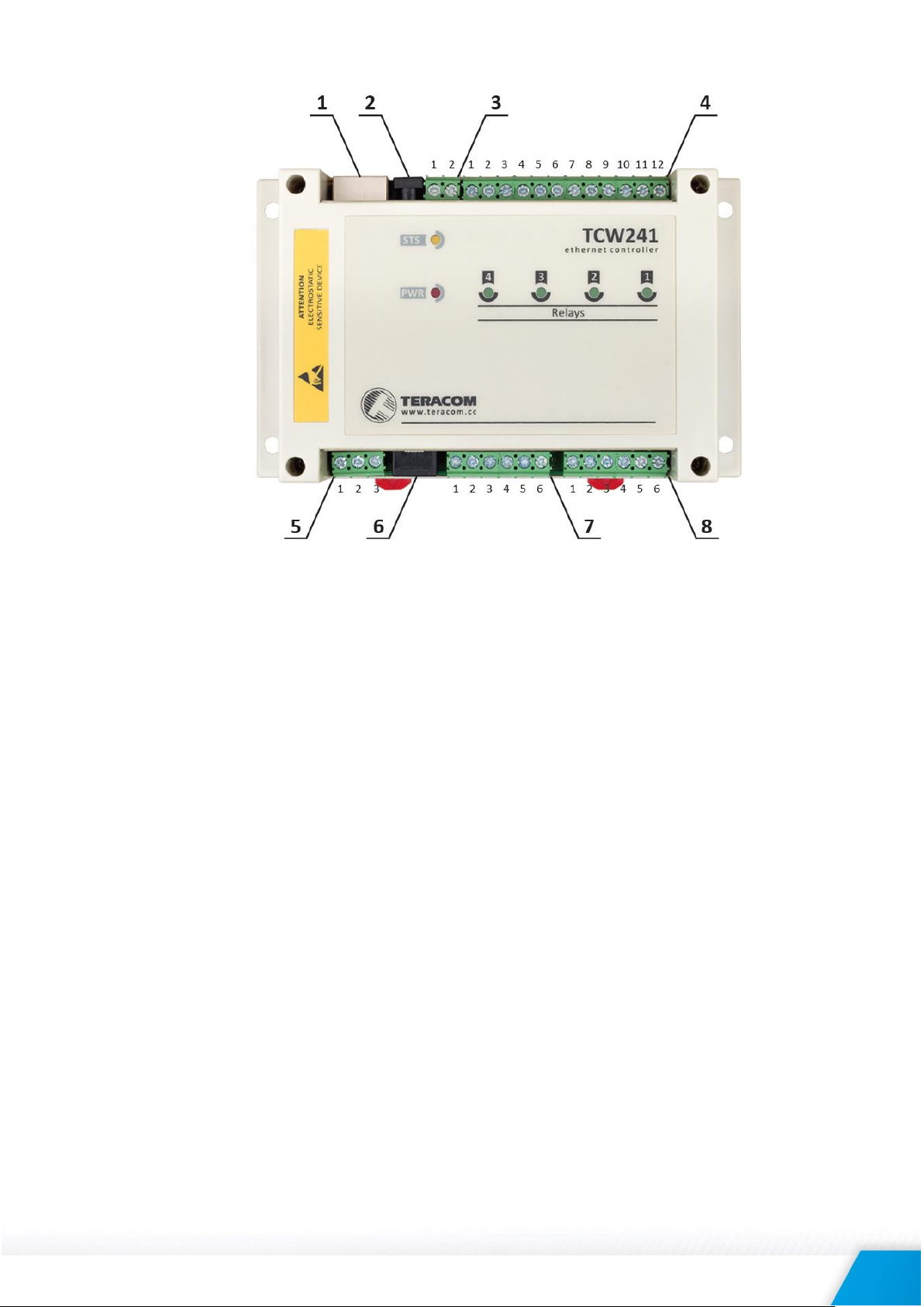
Connector 1 Ethernet - RJ45 Connector 6 Pin1 – GND (most left)
Connector 2 Power - central positive Pin2 – GND
Connector 3 Pin1 – Power positive Pin3 – 1-Wire Data
Pin2 – Power negative Pin4 – 1-Wire GND
Connector 4 Pin1 – NC Relay4 Pin5 – 1-Wire +VDD
Pin2 – COM Relay4 Pin6 – 1-Wire +VDD (most right)
Pin3 – NO Relay4 Connector 7 Pin1 – Digital In 1
Pin4 – NC Relay3 Pin2 – GND
Pin5 – COM Relay3 Pin3 – Digital In 2
Pin6 – NO Relay3 Pin4 – Digital In 3
Pin7 – NC Relay2 Pin5 – GND
Pin8 – COM Relay2 Pin6 – Digital In 4
Pin9 – NO Relay2 Connector 8 Pin1– Analog In 1
Pin10 – NC Relay1 Pin2 – GND
Pin11 – COM Relay1 Pin3 – Analog In 2
Pin12 – NO Relay1 Pin4 – Analog In 3
Connector 5 Pin1 – 1-Wire GND Pin5 – GND
Pin2 – 1-Wire Data Pin6 – Analog In 4
Pin3 – 1-Wire +VDD
6.2.1. Power supply connection
TCW241 is designed to be supplied by adapter SYS1421-0612-W2E or similar, intended for use in
the conditions of overvoltage category II, and prior assessed for compliance with safety
requirements. The power supply equipment shall be resistant to short circuit and overload in a
secondary circuit.
When in use, do not position the equipment so that it is difficult to disconnect the device from
the power supply.
TCW241_R4.1 – April 2017 Page 5
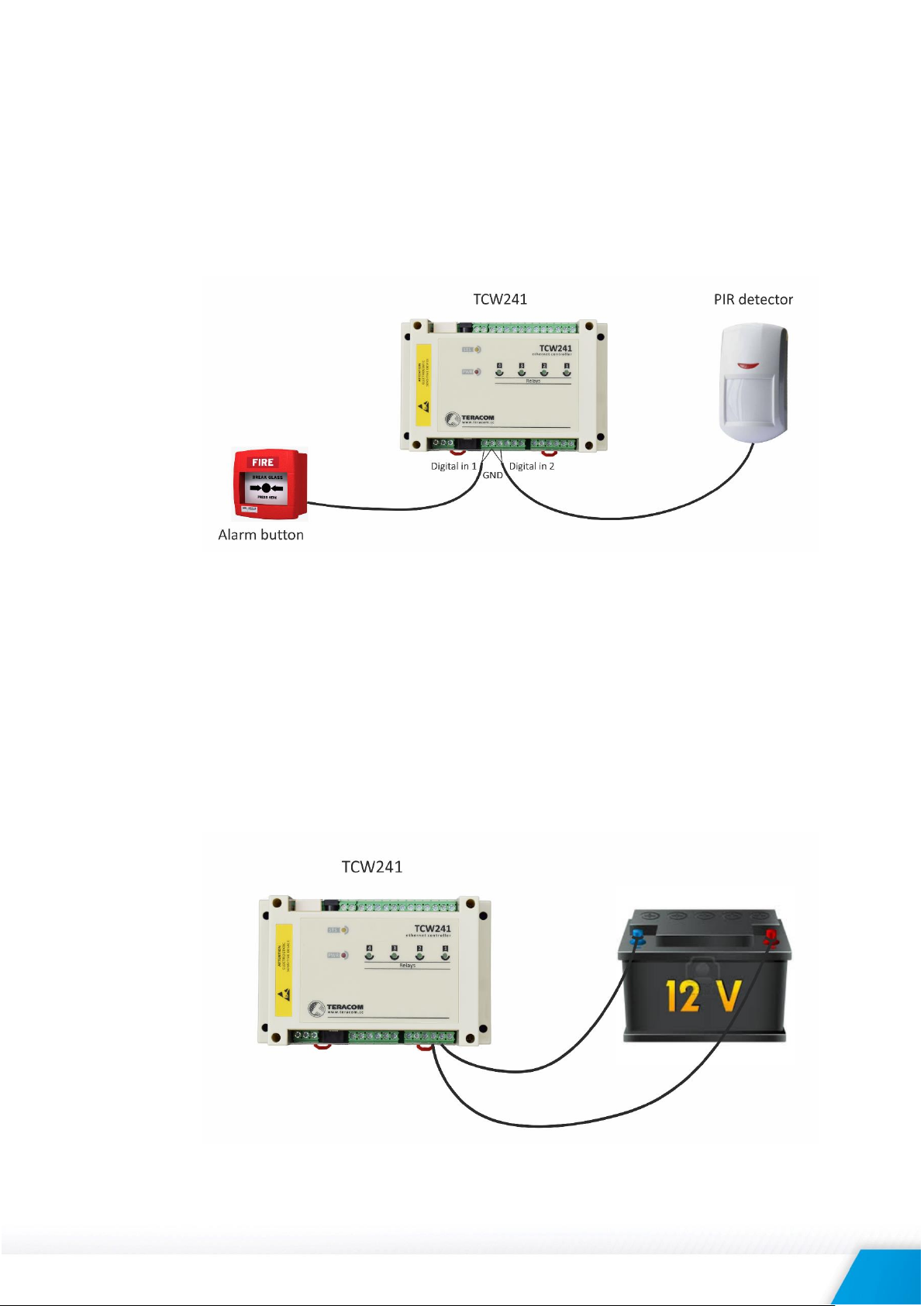
6.2.2. Digital inputs connection
Attention! Digital inputs are NOT galvanic isolated.
The digital inputs of TCW241 can be used for monitoring of devices with “dry contact” outputs –
door contact switch, push button, PIR detector etc.
The following picture illustrates how a dry contact switch can be connected to the input of
TCW241. One side of the contact is connected to “Digital In” and another side is connected to
“GND” terminals.
The maximum cable length should be up to 30 meters.
6.2.3. Analog inputs connection
Attention! Analog inputs are NOT galvanic isolated.
Analog inputs of TCW241 can be used for monitoring of DC voltage up to 60VDC. They can be
connected directly to batteries, solar panels, power supplies etc.
Built in functionality “Multiplier”, “Offset” and “Dimension” for every analog input gives a
possibility to monitor sensors with analog outputs and see directly a measured parameter. It is
also possible to monitor voltages bigger than 60 VDC with external resistive dividers.
The following picture illustrates how a battery can be connected to the analog input of TCW241.
The positive terminal is connected to “Analog In” and the negative terminal to “GND”.
The maximum cable length should be up to 30 meters.
TCW241_R4.1 – April 2017 Page 6
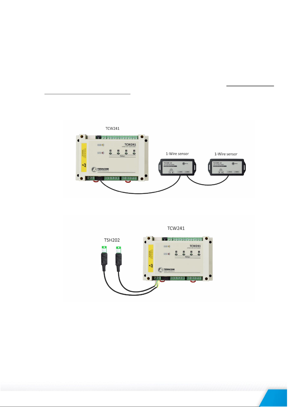
6.2.4. Sensor connection
Up to eight 1-Wire sensors can be connected to TCW241. The device supports following sensors temperature, temperature/humidity, CO2, DC current, AC current, 4/20mA, galvanic isolated
analog voltage, barometric pressure etc. Connected sensors are automatically detected and
appropriate dimension is assigned.
1-Wire is a registered trademark of Maxim Integrated Products, Inc. It is designed to connect
several sensors over a short wiring. It is not suitable for long distances or environments with
EMC interference. We recommend reading Maxim’s 1-Wire tips at http://www.maximic.com/app-notes/index.mvp/id/148.
The sensors have three wires – positive voltage (+VDD), ground (GND) and bidirectional data
(Data). The colors of wires for every sensor are specified in its user manual.
It is strongly recommended to use “daisy-chained” (linear topology) for multiple sensors:
“Star” topology can be used only as a last resort for up to 4 sensors and total cable length up to
10 meters:
Connections can be realized either by screw terminal connector or by a standard RJ-11
connector.
There are many parameters which determine the maximum length of the wires – the type of
cable, the number of sensors, ambient electromagnetic noise and sensor network topology.
It is strongly recommended to use only UTP/FTP cables and keep total cable length up to 30 m.
Although functionality has been achieved in a longer distance, we cannot guarantee error-free
operation over mentioned wiring length.
We guarantee proper operation only with Teracom 1-Wire sensors.
TCW241_R4.1 – April 2017 Page 7
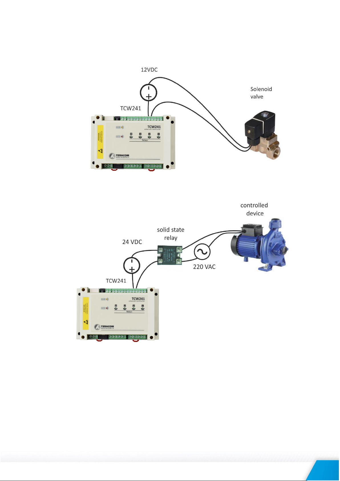
6.2.5. Relay connection
The relay contacts are internally connected directly to the terminal connectors. For all relays normally
open, normally closed and common contacts are available.
For loads with higher switchable current/voltage than specified, an external relay should be
used.
When mechanical relays switch inductive loads such as motors, transformers, relays, etc., the
current will arc across the relay contacts each time the contacts open. Over time, this cause
wears on the relay contacts which shorten their life. When switching an inductive load, it is
recommended that relay contact protection devices are used.
TCW241_R4.1 – April 2017 Page 8
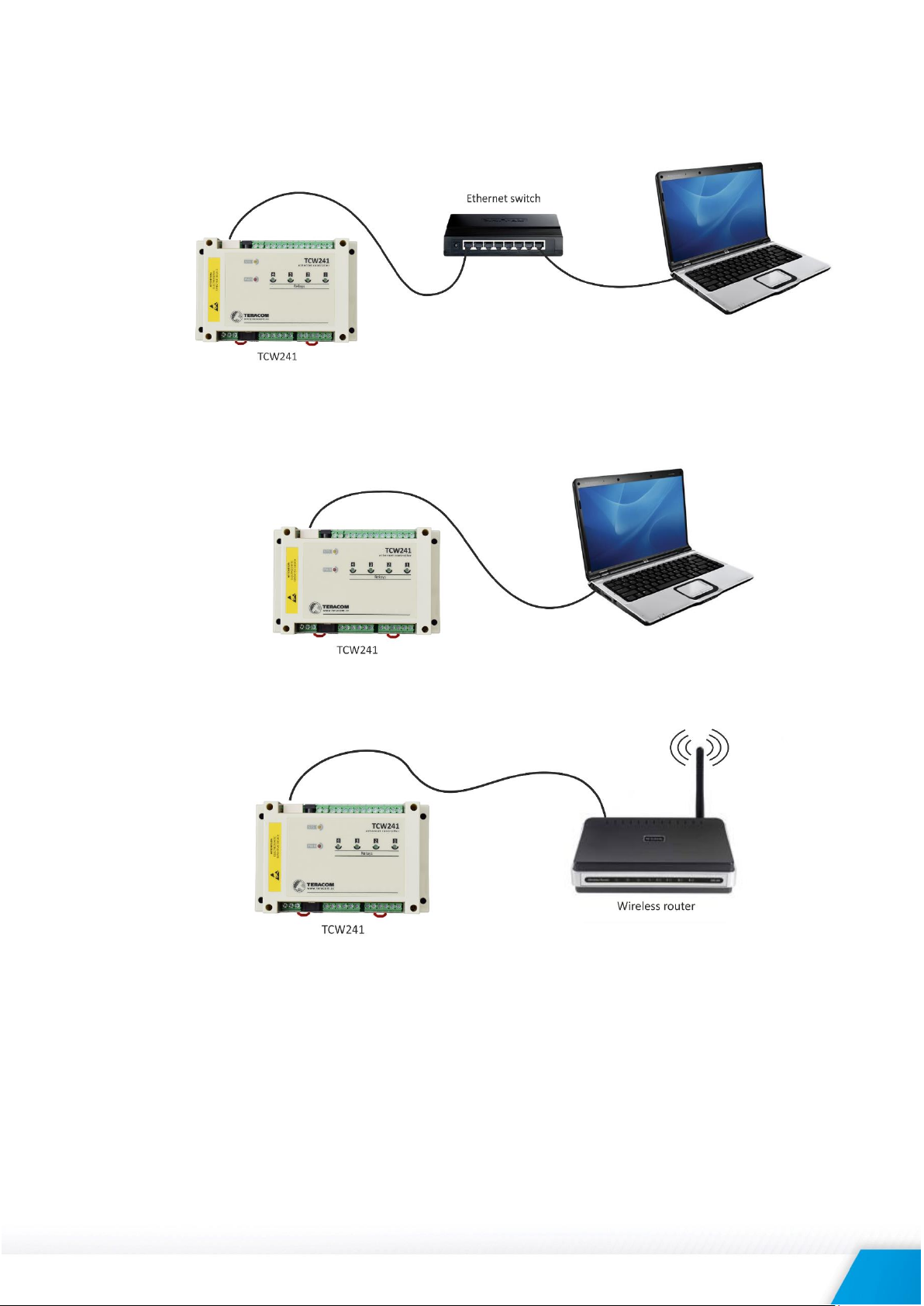
6.2.6. Network connection
The Ethernet port of TCW241 should be connected to 10/100 Base-T Ethernet hub, switch or
router.
For configuration, TCW241 may be connected directly to the Ethernet port on a computer. The
device support Auto-MDIX and it is not necessary to use “crossover” cable, standard “straight-
through” can be also used.
TCW241 can be used in a wireless network by connecting through a wireless router.
6.3. Communication setup
By default TCW241 is delivered with the following network settings:
IP address: 192.168.1.2, Subnet Mask: 255.255.255.0, Default Gateway: 192.168.1.1
Communication with TCW241 can be established by assigning a temporary IP address to the
computer. For computers with Windows OS assigning of IP address is made in “Local area
connection properties”:
TCW241_R4.1 – April 2017 Page 9
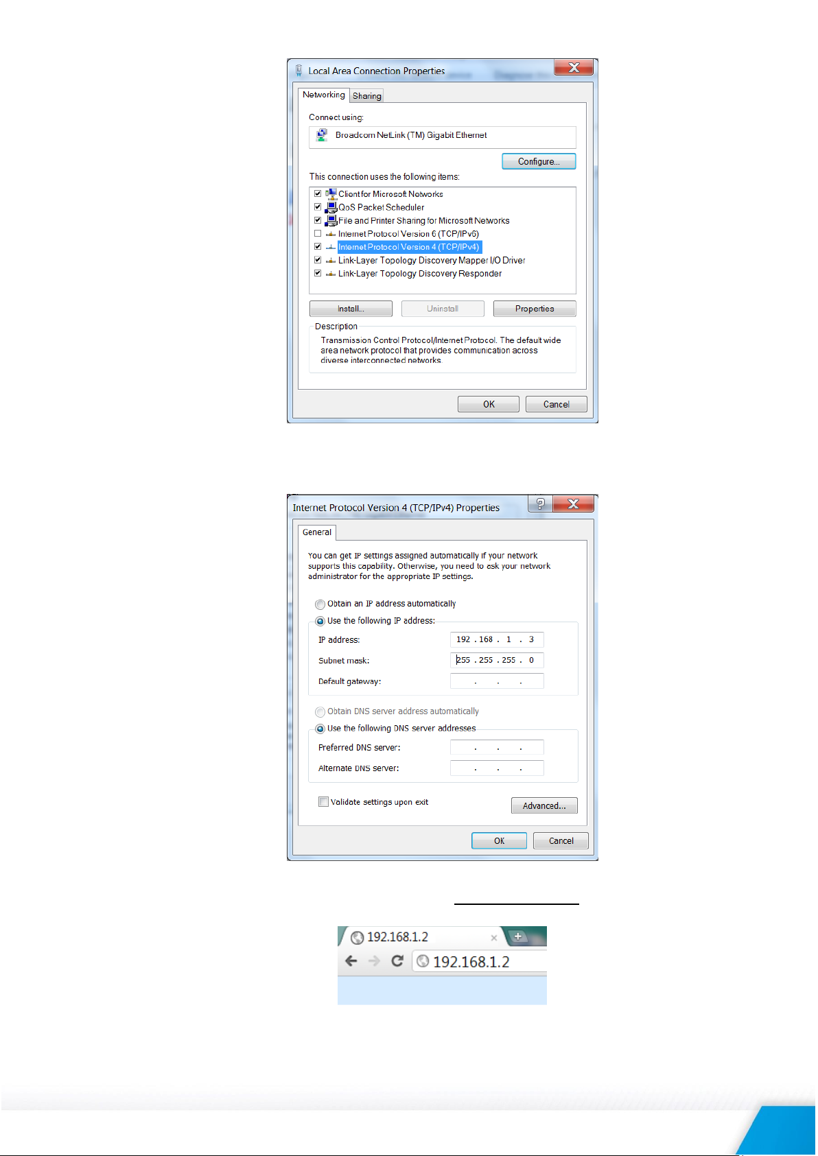
This address should be on the same network - for example 192.168.1.3:
To get access to the web interface, you should type http://192.168.1.2 into the browser.
TCW241_R4.1 – April 2017 Page 10
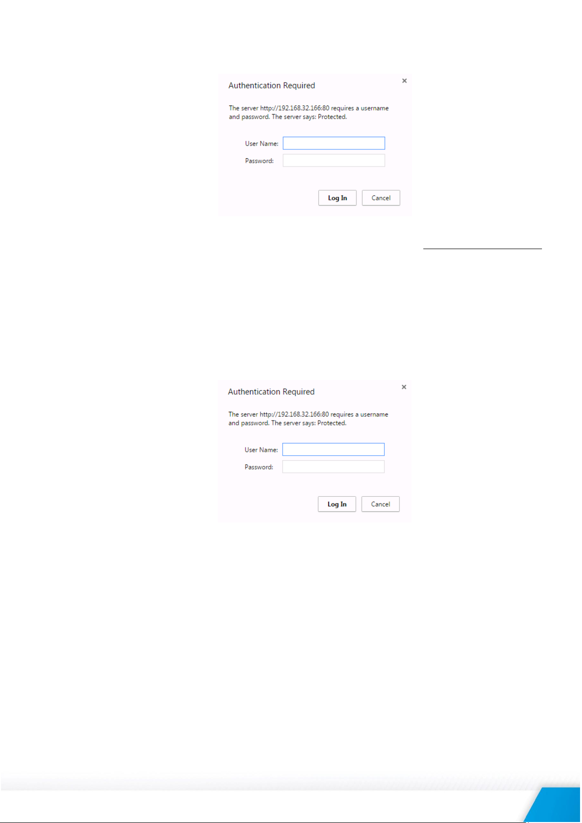
If the network settings are correct, the login pop-up window will appear:
All TCW controllers connected to LAN can be easily found by free tool “TCW discoverer”.
It is available for Win and Mac operating systems and can be downloaded from www.teracomsystems.com
7. Web interface
The web interface allows configuration, monitoring, and control.
All pages are UTF-8 encoded.
If the controller is properly addressing, login pop-up window appears.
Authorization data must be entered (by default username=admin, password=admin).
It is recommended to change the username and password to prevent unauthorized access to the
controller.
The controller supports a few active session.
7.1. Monitoring page
Monitoring page displays the current state of TCW241.
The page has 4 sections – “Sensors”, “Digital inputs”, “Analog inputs” and “Relays”. All they can be
added/removed from monitoring page independently by appropriate setup - see “Setup-SystemDisplay” section.
For every parameter (sensor, input, relay) there is a description of up to 15 characters. Default ones
can be changed in “Setup-Input/Output”.
The Monitoring page can be automatically refreshed on an interval of 0 to 253 seconds. Zero means
no automatic refresh. This parameter is set in section “Setup-System-Monitoring page automatic
refresh”. By default, it is 1 second.
7.1.1. Data - sensors section
All detected 1-Wire sensors are shown in this section.
Detection is made either after power on or by button “Scan for new sensors”. All found sensors
are shown in ascending order refer their unique ID number.
TCW241_R4.1 – April 2017 Page 11
For every sensor, there are a description, value, and ID information.
Teracom 1-Wire sensors readings are shown in the Value 1 column. Dual sensors such as the
(TSH2xx) temperature/humidity sensors have the 2-nd parameter shown in the Value 2 column.
It is possible to lock sensors in a specific position. To do this all sensors should be added one by
one. After every addition, a new scan should be made and newly found sensor should be locked
in its position. If all sensors are locked, removing one “in the middle” will not change the
positions of other sensors after reset. This option is very useful when TCW241 is used us a part of
monitoring and control system managed either by SNMP or HTTP API commands.
For some sensors “Unit”, “Multiplier” and “Offset” can be set in section “Setup-Input/Output”.
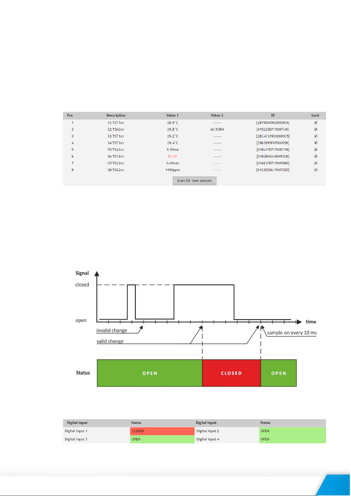
7.1.2. Data - digital inputs section
Digital inputs can be used for monitoring the state of discrete devices – motion sensor, door
contact, relay contact, alarm output etc. All digital inputs are not galvanic isolated.
One side of the contact is connected to “Digital In” and another side is connected to “GND”
pins.
Digital inputs are sampled every 10mS. The change of input status is considered valid if the
same value is read in 3 consecutive samples (30mS) and low-to-high/high-to-low delays
(Setup->Conditions) are zero.
Status of every input is shown by text and by color. The color is red if the input is in an alarm
condition.
Default descriptions can be changed in “Setup-Input/Output”.
TCW241_R4.1 – April 2017 Page 12
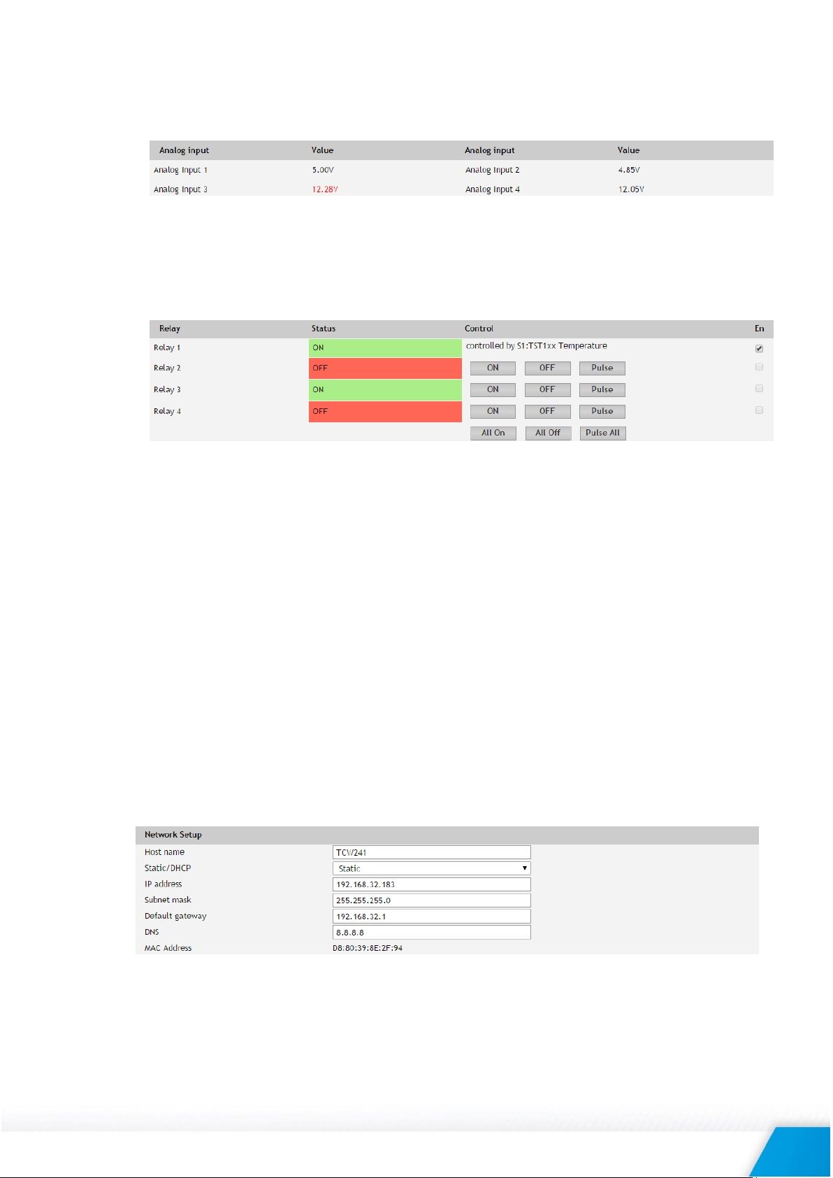
7.1.3. Data - analog inputs section
Analog inputs can be used for monitoring of analog sensors with 0-60 voltage outputs.
All analog inputs are not galvanic isolated.
For every analog input 3 variables – “Unit”, “Multiplier” and “Offset” can be set in section
“Setup-Input/Output”.
7.1.4. Relay section
The section displays the current state of relays and presents buttons that can be used to change their
status.
Each relay can be activated either remotely by the WEB interface, HTTP API and SNMP or locally,
from the status of a monitored parameter (1 Wire sensor, analog voltage and dry contact).
The local control of relay can be arranged either by one parameter or by “any alarm” condition.
For WEB control every relay has “On”, “Off” and “Pulse” buttons. There are also “All On”, “All
Off” and “Pulse All” for common control of relays. Pulse duration in seconds can be set
separately for each relay in “Setup-Input/Output-Relay Outputs”.
For locally activated relays a text description of the controlling parameter is displayed rather
than buttons. Parameters for local relay activation can be set in “Setup-Input/Output-Relay
Outputs”. Control of relays follows conditions set in “Setup-Alarm conditions”.
For every locally activated relay, there is check box “En”. It allows temporarily то turn off the
automatic control, make manual changes by buttons and then again return to automatic control.
By default, this check box is turned off.
7.2. Setup page
7.2.1. Network
The network parameters are set in this section.
The controller supports static and dynamic IP addresses.
It is good practice to change the default IP address of controller immediately after first power-
on. This will avoid collisions if many devices are used on the same network.
It may be necessary to clear the arp cache, each time you connect a new device to the network.
This is done by typing arp -d in the command prompt window of the computer.
The “Host name” is up to 15 characters. It is shown in search results of TCW discoverer.
TCW241_R4.1 – April 2017 Page 13
It is recommended to use public DNS server (8.8.8.8, 8.8.4.4 etc.) rather than default gateway.
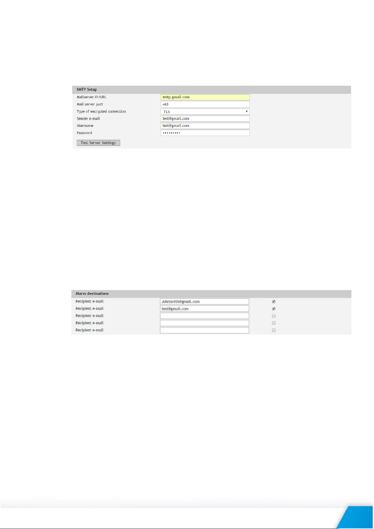
7.2.2. SMTP
This page is used to enter valid SMTP settings for email alerts and recipients’ addresses.
7.2.2.1. SMTP setup
Mail server address can be set either by hostname (www.gmail.com) or IP address.
By default, without encrypted connection, SMTP port is 25. Ask ISP if default port doesn’t
work.
Sender e-mail, username, and password are standard authentication details. For most SMTP
servers sender e-mail and username are the same.
There is a button for server settings test with a feedback. In this test sender and recipient of
the e-mail is the same.
Transport Layer Security protocol is used for security communication with public mail servers.
TCW220 supports – TLS 1.0, TLS 1.1 and TLS 1.2 with RSA_WITH_AES_128_GCM_SHA256 and
RSA_WITH_AES_128_CBC_SHA cipher suites. This ensures successful operation with almost all
public servers
7.2.2.2. Alarm destination
Up to 5 mail recipients can be set. All they can be activated independently by check box.
TCW241_R4.1 – April 2017 Page 14
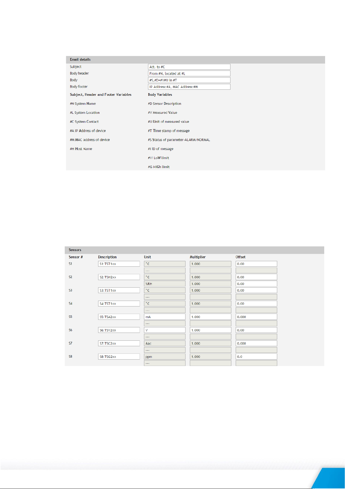
7.2.2.3. E-mail details
The subject, body header, body and body footer can be customized. For this customization, a
set of keys is used. All they are described on the page.
7.2.3. Input/Output
7.2.3.1. 1-Wire sensors
For every 1-Wire sensor, a description up to 15 characters can be set.
For all sensors “Offset” field is enabled. Number from this field is used for simple correction of
displayed value.
For some specific sensor, like TSA200, TSV200 etc., fields “Unit” and “Multiplier” are also
available.
TCW241_R4.1 – April 2017 Page 15
 Loading...