

Teracom TCW210-TH, TCW210-H User Manual


1. Introduction
TCW210-TH is a temperature and humidity data logger with an embedded WEB server. Real-time
data and charts of temperature, humidity and dew point can be monitored with a standard web
browser (no special software is needed). Standard protocols as SNMP, MODBUS/TCP, and HTTP/API
are available for M2M applications. The device supports also interface to popular IoT analytics –
ThinkSpeak.
The Ethernet temperature logger supports up to eight temperature or humidity-temperature
sensors. All they can be connected either to the 1-Wire interface, popular for home automation or
to more robust MODBUS RTU over RS-485.
All monitored parameters can be recorded, in internal FLASH memory. The records are made on the
previous set time interval and/or on an alarm condition. The memory is large enough for at least 36
days with records on every minute. The log file can be periodically uploaded on a dedicated server
by HTTP Post.
For every monitored parameter e-mails and SNMP traps for up to 5 recipients can be sent. Alarm
alert can also be sent by HTTP Post with XML/JSON status files.
2. Features
Data logger for up to 70000 records;
1-Wire and MODBUS RTU sensors support;
HTTP API commands;
Periodical HTTP Post of XML/JSON status files for client-server systems;
SNMP v.2 support;
SNMP traps to up to 5 recipients like alarm alert;
MODBUS TCP/IP support;
SMTP with TLS encryption;
e-mails to up to 5 recipients like alarm alert;
ThinkSpeak service support;
NTP support;
Back-up/Restore of configurations;
Dynamic DNS support;
10/100 Mb Ethernet connectivity;
Auto-MDIX;
Port changing for HTTP, SNMP and MODBUS TCP/IP;
Password protected WEB based configuration and control;
Extended working temperature range;
Wide power supply voltage range;
Remote firmware update.
TCW210-TH-R1.2 - January 2018 Page 1

3. Applications
Supply voltage, VDC
10 - 32
Maximum current, mA
170@12VDC
Weight, g
140
Dimensions, mm
130 х 70 х 30
Operating temperature, °C
-20 to +55
Maximum humidity, %RH
70 (non-condensing)
Supply voltage for 1-Wire bus, VDC
5.0 ± 0.3
Supply voltage for RS-485 bus, VDC
5.0 ± 0.3
Maximum output current for 1-Wire and RS485 buses, A
0.2
TCW210-TH is suitable for environmental monitoring, building, and industrial automation.
It works very well for monitoring temperature and humidity as a standalone device using a WEB
browser only or as a part of small to large industrial control systems for SCADA (supervisory control
and data acquisition).
A few application example - pharmaceutical and food processing and storage, clean rooms,
laboratories, HVAC systems, greenhouses and farms, electronic assembly etc.
4. Technical parameters
5. LED indicators
The following indicators show the status of the controller:
PWR (red) – in working mode shines, flashes together with STS if there is a hardware
error;
STS (yellow) – flashes when the main program of the controller is executed;
NET (orange) – indicates the network connection status - ON when a link is established,
flashing when there is an activity.
6. Installation and setup
This device must be installed by qualified personnel.
This device must not be installed directly outdoors.
The installation consists of mounting the device, connecting to an IP network, connecting inputs and
outputs, providing power and configuring via a web browser.
6.1. Mounting
TCW210-TH should be mounted in a clean and dry location on a not flammable surface.
Ventilation is recommended for installations where the ambient air temperature is expected to
be high.
Maintain spacing between adjacent equipment. Allow 50 mm of space on all sides, as shown in
Appendix A, this provides ventilation and electrical isolation.
6.2. Connection
Attention! Disconnect power supply before wiring.
The correct wiring procedure is as follows:
Make sure power is turned off;
Apply all sensors;
Apply power.
Make sure that cables are properly attached. Not proper wiring and configuration can cause
permanent damage to TCW210-TH or the equipment to which it is connected or both.
TCW210-TH-R1.2 - January 2018 Page 2
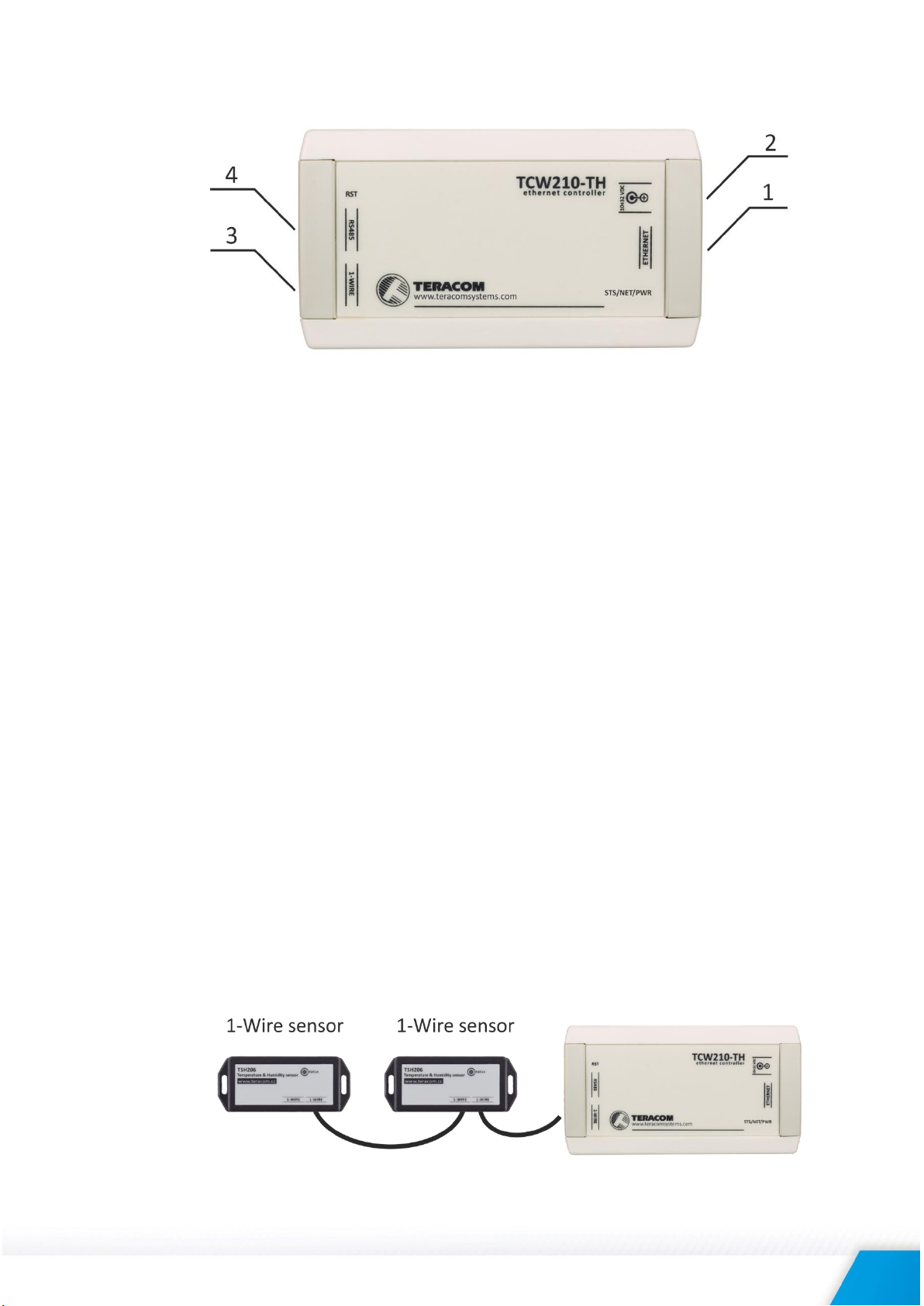
Connector 1
Ethernet - RJ45
Connector 4
Pin1 – not connected (most left)
Connector 2
Power - central positive
Pin2 – not connected
Connector 3
Pin1 – GND (most left)
Pin3 – not connected
Pin2 – GND
Pin4 – Line B-
Pin3 – 1-Wire Data
Pin5 – Line A+
Pin4 – 1-Wire GND
Pin6 – not connected
Pin5 – +VDD
Pin7 – +VDD
Pin6 – +VDD (most right)
Pin8 – GND
6.2.1. Power supply
TCW210-TH is designed to be supplied by adapter SYS1421-0612-W2E or similar, intended for
use in the conditions of overvoltage category II, and prior assessed for compliance with safety
requirements. The power supply equipment shall be resistant to short circuit and overload in
a secondary circuit.
When in use, do not position the equipment so that it is difficult to disconnect the device from
the power supply.
6.2.2. 1-Wire interface
1-Wire is a registered trademark of Maxim Integrated Products, Inc. It is designed to connect
several sensors over a short wiring. It is not suitable for long distances or environments with
EMC interference.
The maximum number of sensors (1-Wire or RS-485) connected to TCW210-TH is 8.
The device supports temperature and humidity-temperature sensors. Connected sensors are
automatically detected and appropriate dimension is assigned.
It is strongly recommended to use “daisy-chained” (linear topology) for multi-sensors systems:
TCW210-TH-R1.2 - January 2018 Page 3
It is strongly recommended to use only UTP/FTP cables and keep total cable length up to 30m.
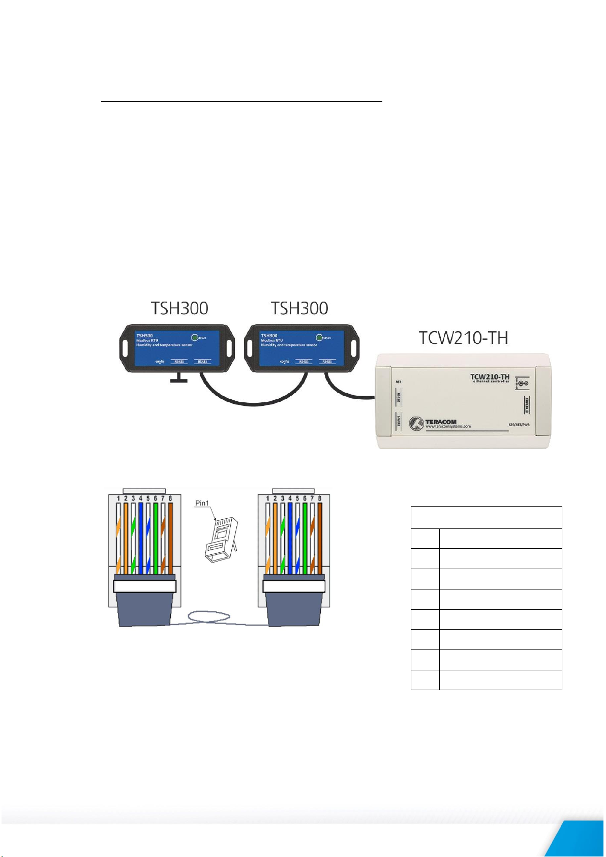
Pin# RJ45
1
Orange/White Tracer
2
Orange
3
Green/White Tracer
4
Blue
5
Blue/White Tracer
6
Green
7
Brown/White Tracer
8
Brown
Although functionality has been achieved in the longer distance, we cannot guarantee errorfree operation over mentioned wiring length. We recommend reading Maxim’s 1-Wire tips at
http://www.maxim-ic.com/app-notes/index.mvp/id/148.
We guarantee proper operation only with Teracom 1-Wire sensors.
6.2.3. RS-485 interface
RS-485 is a standard for serial communications systems defined by Telecommunications
Industry Association (TIA) and Electronic Industries Alliance (EIA). Implementing the standard,
communication systems can be used effectively over long distances and in electrically noisy
(industrial) environments.
The maximum number of sensors (1-Wire or RS-485) connected to TCW210-TH is 8.
The device supports temperature and humidity-temperature sensors.
MODBUS RTU protocol specifies that address of the device should be between 1 and 247. The
user should take care of appropriate address settings.
For multi-sensors systems “daisy-chained” (linear topology) should be used:
Interconnections are realized by UTP/FTP cables with RJ-45 connectors. The popular Ethernet
wiring standard ANSI/TIA/EIA T568B is used:
It is recommended to use standard patch cables for LAN networks.
Special attention should be paid on termination of the bus in the last sensor.
We recommend keeping total cable length up to 30 m, although the RS-485 interface works
over much longer distance.
TCW210-TH-R1.2 - January 2018 Page 4
Attention!
Special attention should be paid on termination of the bus.
The last sensor in the chain should have a terminator installed on the free RJ-45 socket.
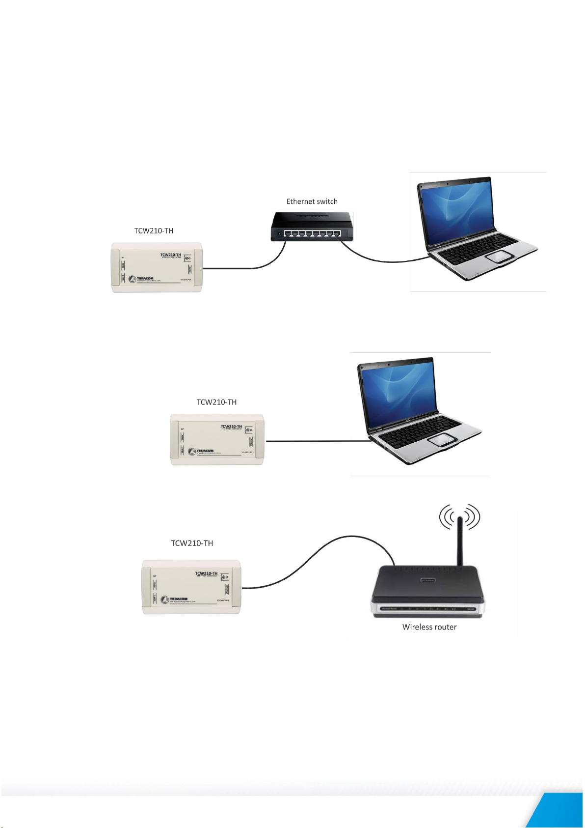
6.2.4. Network connection
The Ethernet port of TCW210-TH should be connected to 10/100 Base-T Ethernet hub, switch
or router.
For setup, TCW210-TH may be connected directly to the Ethernet port on a computer. The
device support Auto-MDIX and it is not necessary to use “crossover” cable, standard “straightthrough” can be also used.
TCW210-TH can be used in a wireless network by connecting through a wireless router.
TCW210-TH-R1.2 - January 2018 Page 5
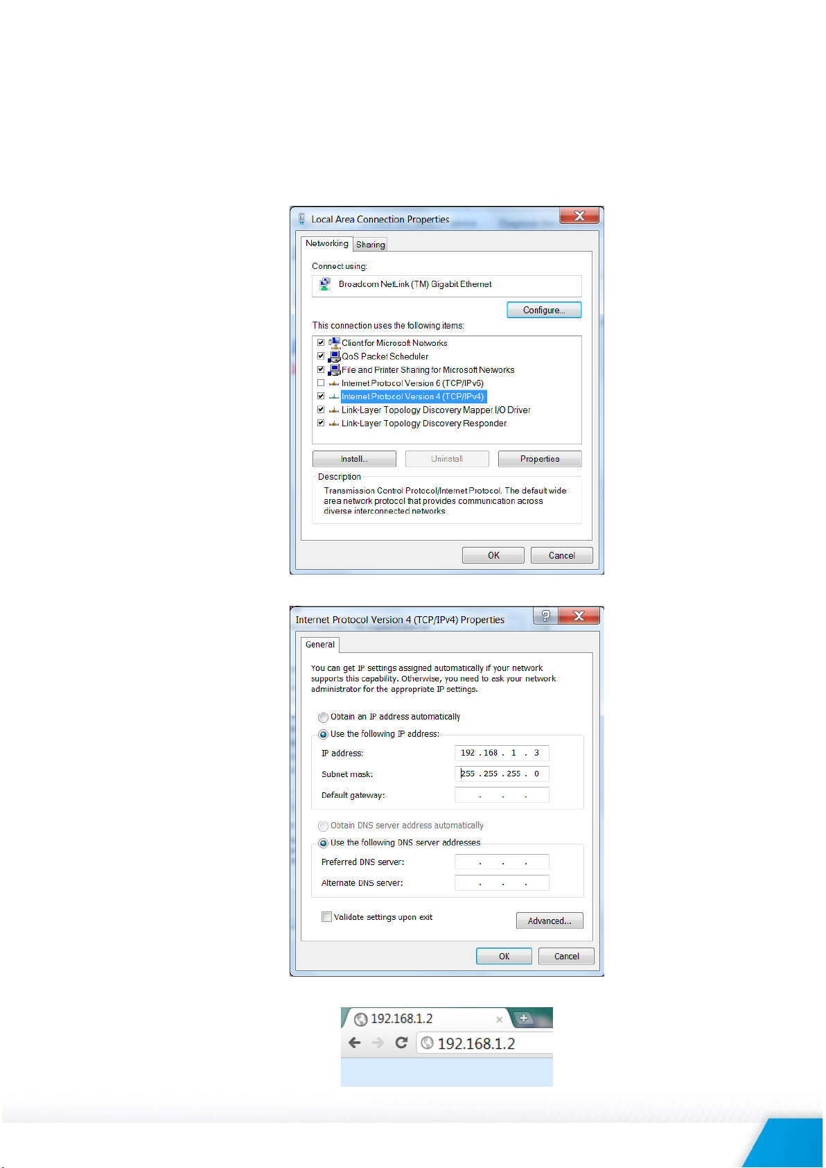
6.3. Communication setup
By default TCW210-TH is delivered with the following network settings:
IP address: 192.168.1.2, Subnet Mask: 255.255.255.0, Default Gateway: 192.168.1.1
Communication with TCW210-TH can be established by assigning a temporary IP address to the
computer. For computers with Windows OS assigning of IP address is made in “Local area
connection properties”:
The address should be on the same network - for example 192.168.1.3:
To get access to the web interface, you should type http://192.168.1.2 into the browser:
TCW210-TH-R1.2 - January 2018 Page 6
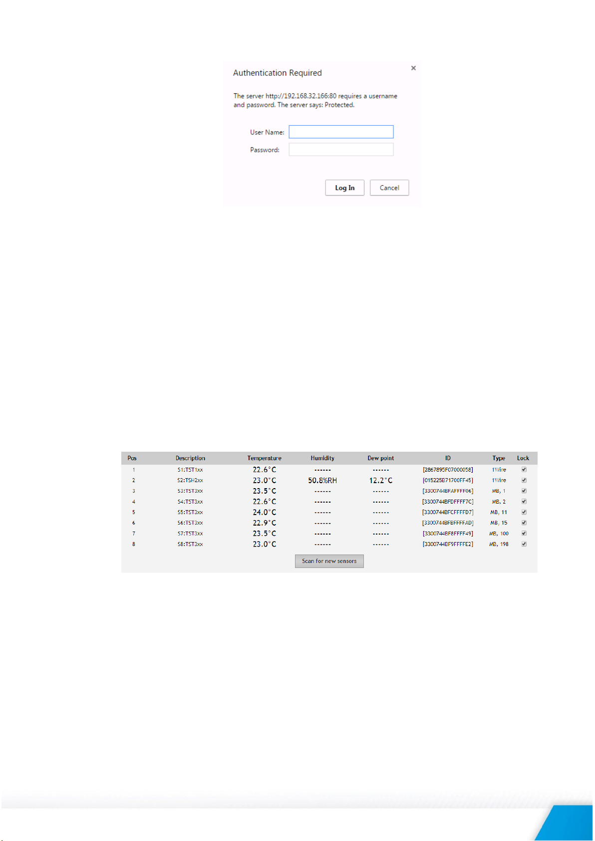
If the network settings are correct, the login pop-up window will appear:
All TCW controllers connected to LAN can be easily found by the free tool “TCW discoverer”.
It is available for Win and Mac operating systems and can be downloaded from
www.teracomsystems.com.
7. Web interface
The web interface allows configuration, monitoring, and control. All pages are UTF-8 encoded.
If the controller is properly addressing, login pop-up window appears.
Authorization data must be entered (by default username=admin, password=admin).
It is recommended to change the username and password to prevent unauthorized access to the
controller.
The controller supports a few active session.
7.1. Monitoring
Monitoring page displays the current state of TCW210-TH. It has one data and four graphs tabs.
7.1.1. Data
The current state of TCW210-TH can be monitored on this page.
All detected 1-Wire/MODBUR RTU sensors are shown in this section.
Detection is made either after power on or by button “Scan for new sensors”. All found
sensors are shown in ascending order refer their unique ID number.
For every sensor, there are a description, value, and ID information. The description length is
up to 15 characters. Default descriptions can be changed in “Setup-Conditions”.
Dual sensors (humidity-temperature) have the two parameters. For these sensors, Dew point
parameter is calculated automatically.
It is possible to lock sensors in a specific position. To do this all sensors should be added one
by one. After every addition, a new scan should be made and newly found sensor should be
locked in its position. If all sensors are locked, removing one “in the middle” will not change
the positions of other sensors after reset. This option is very useful when TCW210-TH is used
as a part of monitoring and control system managed either by SNMP or HTTP API commands.
TCW210-TH-R1.2 - January 2018 Page 7
The page can be automatically refreshed on an interval of 0 to 253 seconds. Zero means no
automatic refresh. This parameter is set in section Setup->System->Monitoring page
automatic refresh. By default, it is 1 second.
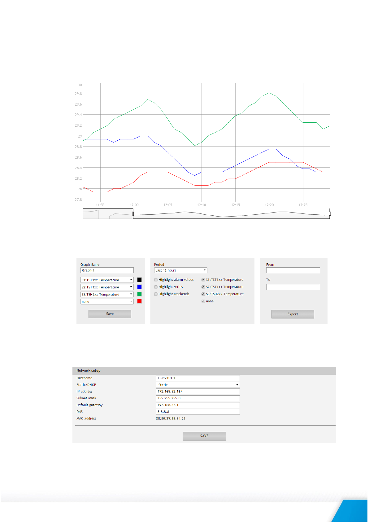
7.1.2. Graphs
Every graph page can display up to 4 parameters with up to 2 different dimension.
For every parameter different color can be set. There are a few checkboxes for display
modification.
Export of monitored parameters can be made from the page.
7.2. Setup
7.2.1. Network
The network parameters are set on this page.
The controller supports static and dynamic IP addresses.
It is good practice to change the default IP address of controller immediately after first power-
on. This will avoid collisions if many devices are used on the same network.
TCW210-TH-R1.2 - January 2018 Page 8
It may be necessary to clear the arp cache, each time you connect a new device to the
network. This is done by typing arp -d in the command prompt window of the computer.
The “Hostname” is up to 15 characters. It is shown in search results of TCW discoverer.
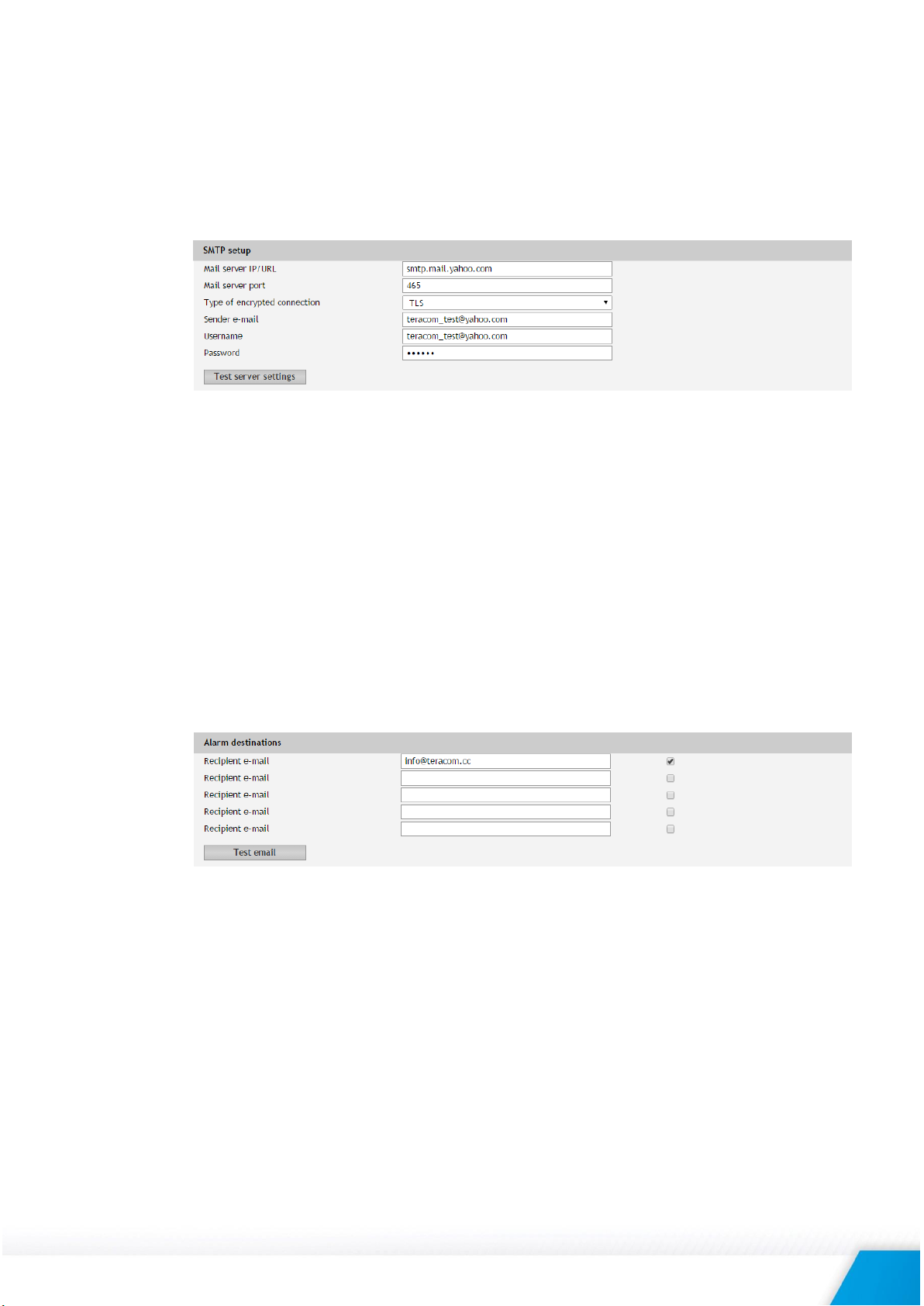
7.2.2. SMTP
This page is used to enter valid SMTP settings for email alerts and recipients’ addresses.
7.2.2.1. SMTP setup
Mail server address can be set either by hostname (for example smtp.mail.yahoo.com) or
by IP address.
By default, without encrypted connection, SMTP port is 25. Ask ISP if default port doesn’t
work.
Sender e-mail, username, and password are standard authentication details. For the most
SMTP servers, sender e-mail and username are the same.
There is a button for server settings test with a feedback. In this test sender and recipient
of the e-mail is the same.
Transport Layer Security protocol is used for secure communication with public mail
servers. The device supports – TLS 1.0, TLS 1.1 and TLS 1.2 with
RSA_WITH_AES_128_GCM_SHA256 and RSA_WITH_AES_128_CBC_SHA cipher suites. This
ensures successful operation with almost all public servers.
7.2.2.2. Alarm destination
Up to 5 mail recipients can be set. All they can be activated independently by a checkbox.
7.2.2.3. E-mail details
The subject, body header, body and body footer can be customized. For this customization,
a set of keys is used. All they are described on the page.
TCW210-TH-R1.2 - January 2018 Page 9
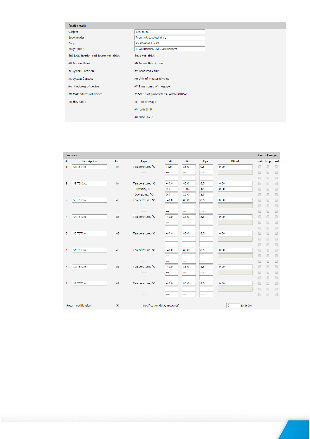
7.2.3. Conditions
This section is used for parameterization of trigger and alert conditions for 1-Wire and
MODBUS RTU sensors.
For every sensor, a description up to 15 characters can be set.
For all sensors “Offset” field is enabled. The offset is used for simple correction of displayed
value.
For every parameter, there is a field for trigger conditions (“Min”, “Max” and “Hys.”).
“Min” and “Max” indicate the border of working range for the observed parameter.
A “Max” trigger condition occurs when the value exceeds the trigger set point. A “Min” trigger
condition occurs when the value is lower than the trigger set point. In both cases, the
monitored parameter goes out of range.
Coming back in range for the observed parameter is considered when the value goes higher
than (Min + Hys) or lower than (Max – Hys). Hysteresis (“Hys”) is used to prevent excessively
triggering when the value vacillates around trigger point.
TCW210-TH-R1.2 - January 2018 Page 10
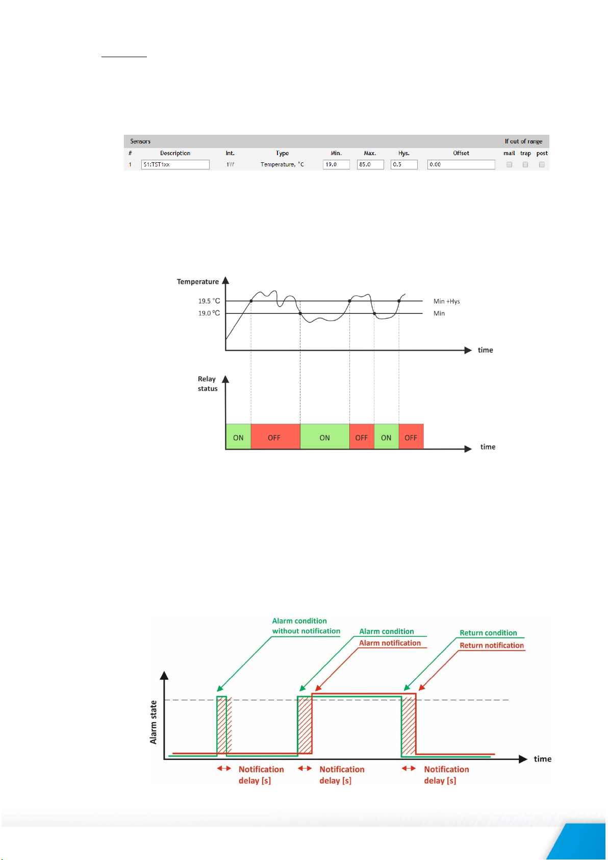
Example:
TCW210-TH and TST103 are used to monitoring of room temperature. The wanted minimum
temperature is 19°C. The initial temperature is 17°C.
TST100 is assigned to the first position for 1-Wire sensors.
Following parameters are set for Sensor1: Min=19, Max=85 and Hys=0.5.
When the controller is switched on, Alarm is immediately activated because the monitored
temperature is out of range.
When the temperature reaches 19.5°C (19.0 + 0.5) it goes in range (trigger condition) and
Alarm is deactivated.
The temperature falls and when it reached 19°C it goes out of range (trigger and alert
conditions). E-mail is sent.
The “Max” value is set far enough from the wanted temperature to avoid trigger/alert
conditions around it.
For every sensor, there are 3 independent ways of alert for alarm condition – e-mail, SNMP
trap and HTTP post of an XML/JSON file. Each alarm notification method is activated by a
checkbox.
Globally for all sensors, there is a checkbox “Return notification”. If this option is chosen there
will be notification also when parameter returns in range.
Globally for all sensors, there are “Notification delay” parameter. It is very useful like a filter
for short alarm conditions.
7.2.4. System
TCW210-TH-R1.2 - January 2018 Page 11
 Loading...