

Teracom TCW180 User Manual
Ethernet controller TCW180
Users manual
1. Short description
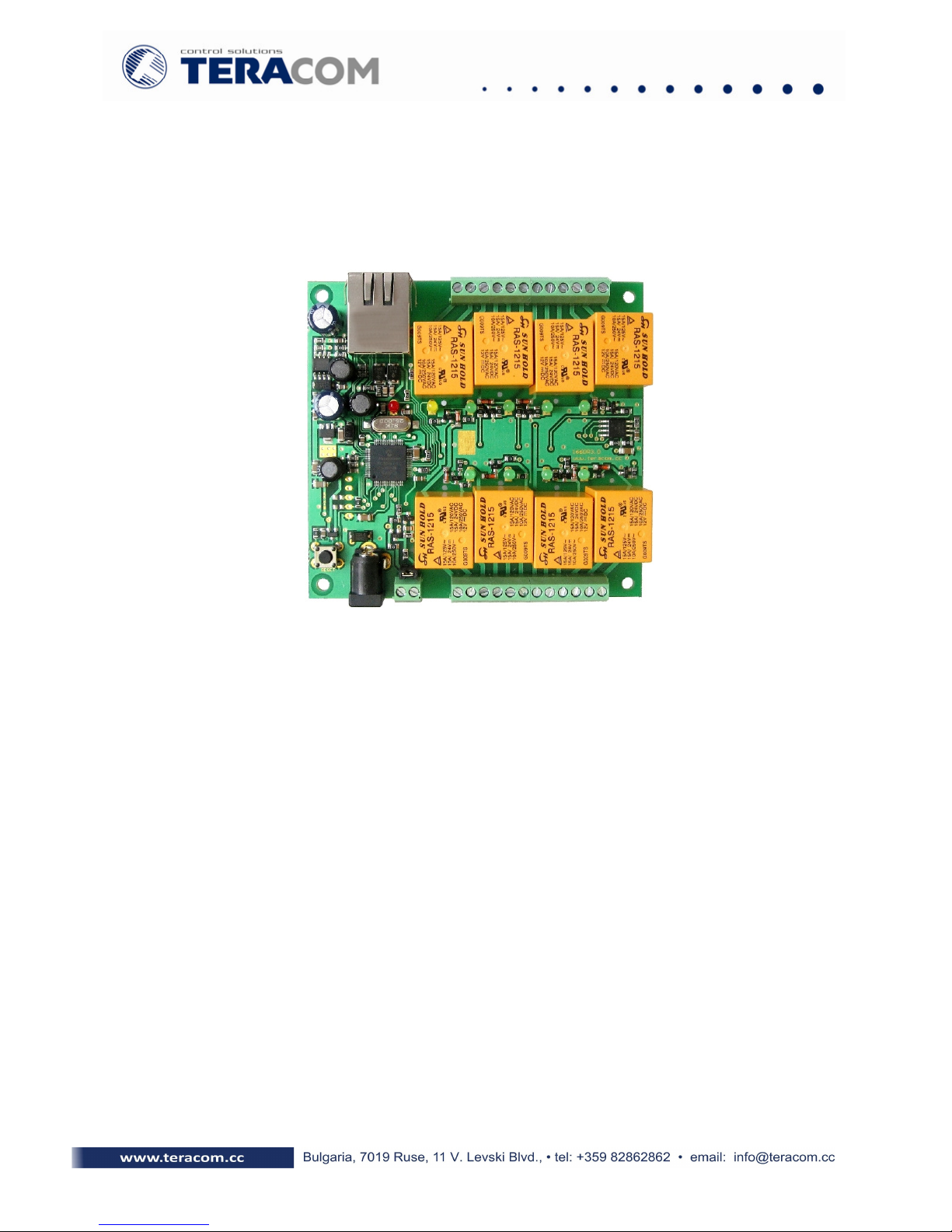
TCW180 is 8-Channel Ethernet relay board, which is designed to work in IP-based
networks and managed by WEB interface or SNMP programs. This device can be used as
standalone or as a part of control and monitoring systems. Its I/O interface - 8 relay outputs
and 1 digital input, is suitable for solving specific problems in various fields such as remote
control, process automation, home automation and others.
2. Features
• 10 Mbit Ethernet connectivity
• Password protected web based configuration and control
• 1 digital input, 8 relay outputs
• SNMP v.1, SMTP, ICMP, VLAN support
• SNMP Trap alert if an event occurs on the digital input
• E-mail alert if an event occurs on the digital input
• TCW180 can be used as standalone device or as a part of monitoring and
management system
• MAC Address filtering
• Remote FTP firmware update
3. Technical parameters
Operating temperature
, °C
0 ÷ 40
Minimum high level input voltage
, V 2.5 Maximum low
level input voltage
, V 0.8
5.5
3
250/
110
Supply Voltage, VDC
Weight, g
Dimensions, mm
12
120
92 x 88 x 18
Storage temperature , °C
Maximum input voltage for digital input, V
Max. switchable current (at 220 VAC) , А
Max. switchable voltage, VAC/VDC
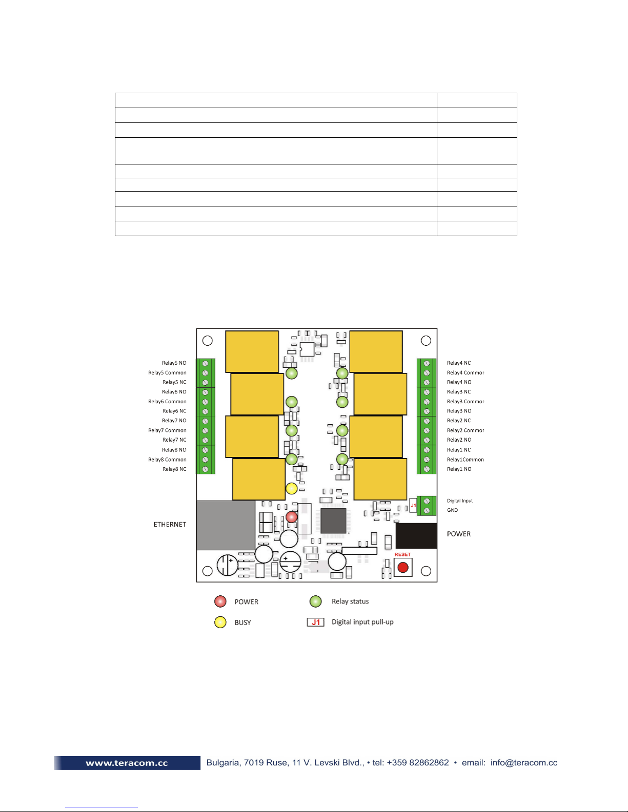
4. Connectors
Inputs and outputs locations are shown below:
-40 ÷ 85
• J1 –mode selection jumper for digital input – dry contact (close) and logic level (open);
• ETHERNET - 10/100-BaseT RJ45 connector
• POWER – ø2mm power jack
5. LED indicators
The following indicators show t he status of the controller :
• Relay status 1÷8 (green) – these LEDs are illuminated whenever the corresponding
relay is activated
• Power (red) – this flashes when the power supply is turned on;
• Busy (yellow) – this LED indicates that someone is connected to the controller
through web interface;
• Link (green) – this LED is located on the Ethernet connector. It indicates that the
device is connected to the network ;
• Act (yellow) – this LED is located on the Ethernet connector. It flashes when activity
is detected on the network.
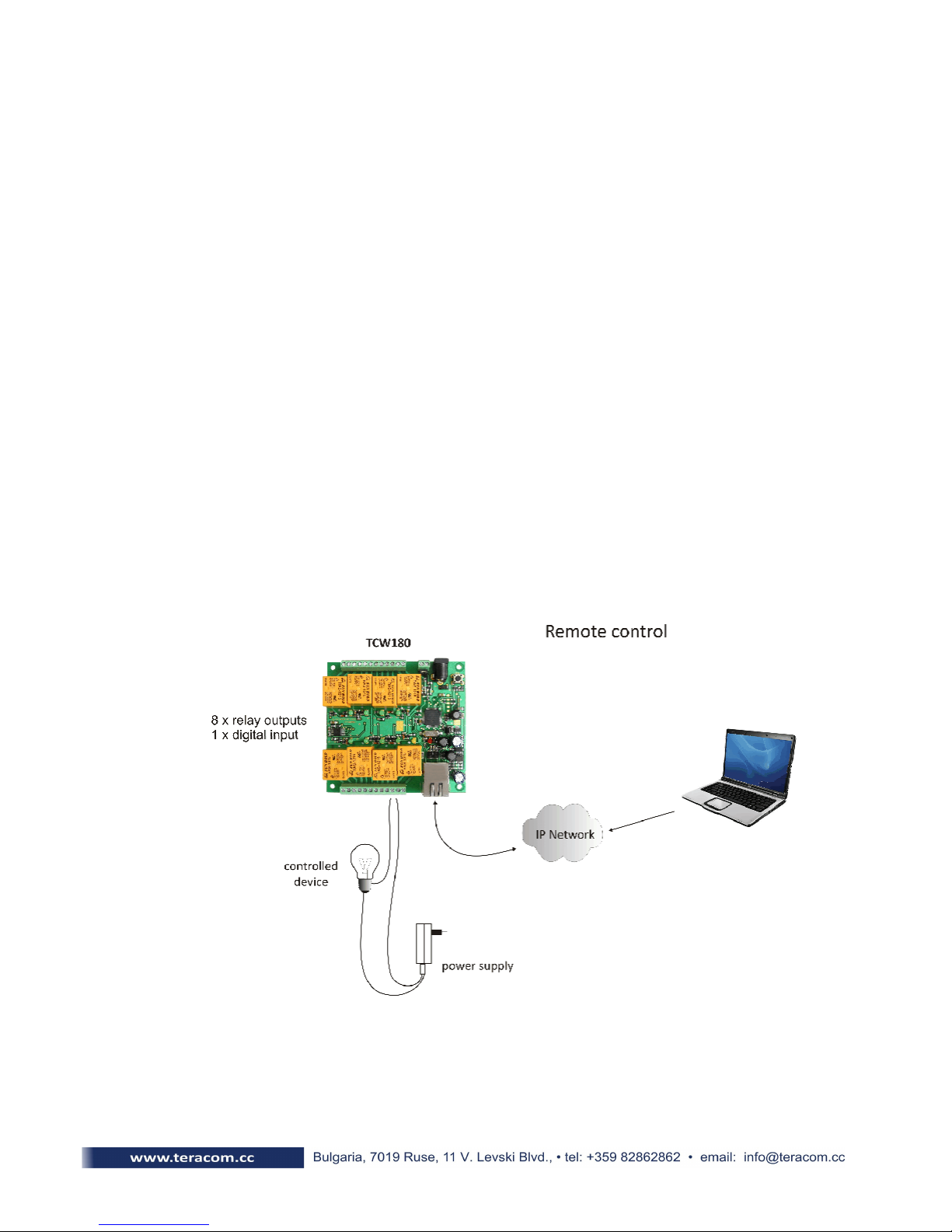
6. Example Application
6.1 Remote control
The controlled device is connected in series with the relay contacts. Users can operate
TCW180 using a web browser or by using custom SNMP applications. The relay outputs are
managed independently of each other.
7. Installation
Please follow the steps below for proper installation :
1. Mount the controller in a dry and ventilated place.
2. Connect the Ethernet port to a 10/100 Base T Ethernet connection. For direct
connection to a PC use a “crossover” cable.
3. Connect the I/O pins of the controller according to the required application.
4. Connect the power supply.
If the red LED is blinking, it indicates that the power supply is OK. By default TCW180 comes
with the following network settings:
IP:192.168.1.2 , Subnet Mask: 255.255.255.0 , Default Gateway: 192.168.1.1
Communication with TCW180 may be established by assigning a temporary IP address to the
configuration computer that is on the same network (for example 192.168.1.3). To get access to
the web interface of the controller, you should type the following URL into the browser :
http://192.168.1 2 . If the network settings are correct, the “Login” page will appear.
8. Web-based setup.
The web based interface allows the TCW180 to be configured, controlled and monitored via
web browser. Recommended programs are Mozilla Firefox, Chrome and Internet Explorer 6 (or
higher version) at 1024x768 resolution.
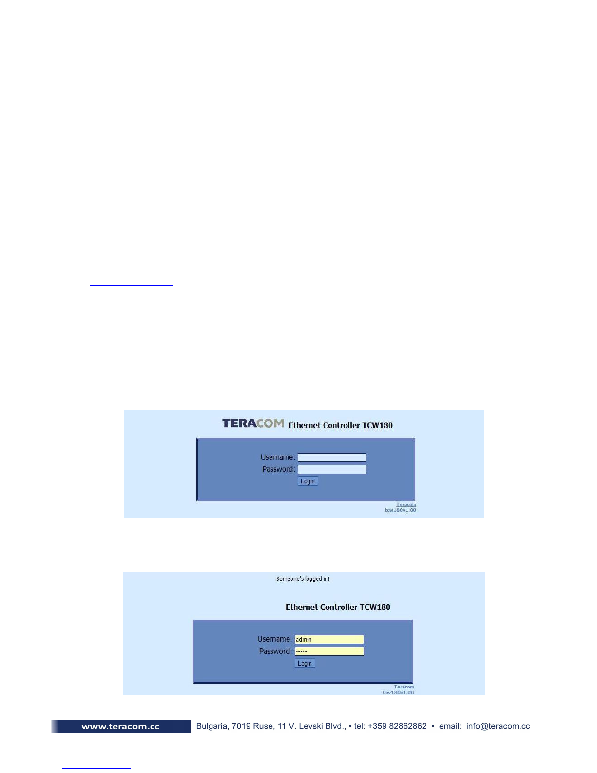
8.1 Login page
After opening the Login page, authorization data must be entered ( by default
username=admin , password=admin). It is recommended to change the username and password
to prevent unauthorized access to the controller.
The controller supports only one active session – only one user (administrator) can operate
the device. If another user tries to login, the following message appears: “Someone’s logged in”
 Loading...