

Teracom TCW122B-WD User Manual
Ethernet controller TCW122B-WD
(Firmware version 2.xx)
User manual
1. Short description
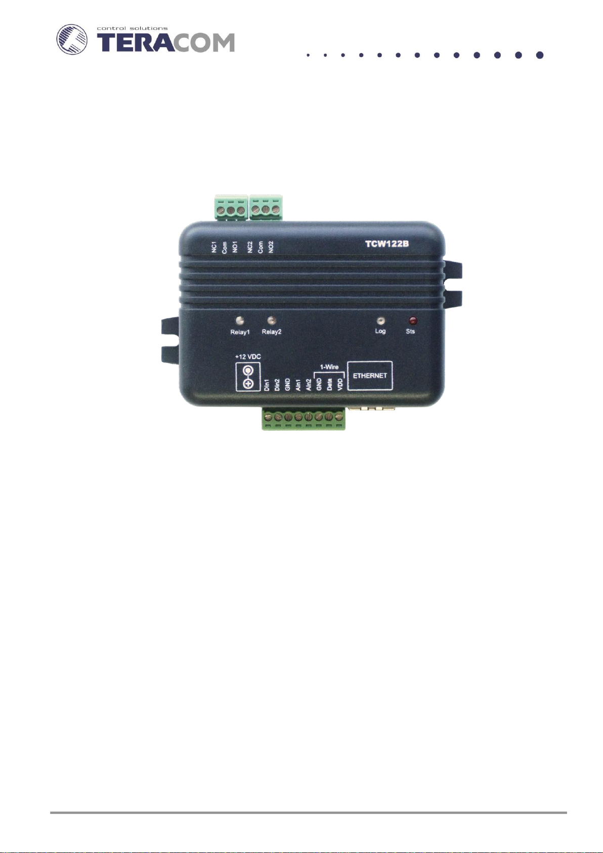
TCW122B-WD is an Ethernet controller, based on TCW122 hardware. It has 2 digital and 2 analog
inputs, 1-Wire interface for up to 2 temperature/humidity sensors and 2 relays with NO/NC contacts. It is
stand-alone device, can be managed by WEB interface and/or SNMP programs
TCW122B-WD is suitable for IP watchdog monitoring, environmental monitoring of server rooms
as well for – building automation, remote control, alarm systems etc.
2. Features
10 Mb Ethernet connectivity;
Password protected, web based configuration and control;
2 digital inputs with " dry contact" and "logic level" modes;
2 analog inputs with 0 to 60VDC range;
2 relays with NO and NC contacts;
Long 1-Wire support for up to 2 temperature (TST1XX) or temperature/humidity (TSH2xx)
sensors;
SNMP v.1 support, SNMP trap alerts;
VLAN, MAC address filtering;
ICMP watchdog monitoring;
Remote firmware update.
TCW122B-WD_R2 ( Firmware version 2.xx ) Page 1
Supply voltage, VDC
12±2
Maximum current consumption (with both relays ON), mA
200
Weight, g
110
Dimensions, mm
107 x 72 x 32
Operating temperature, °C
0 to +40
Maximum humidity in 0 to 31°C range, %RH
80
Maximum humidity at 40°C (linear slope between 31-40°C), %RH
50
Minimum high level input voltage for digital inputs, VDC
+2.5
Maximum low level input voltage for digital inputs, VDC
+0.8
Maximum input voltage for digital inputs, VDC
+5.5
Supply voltage for 1-wire bus (VDD), VDC
5.3 ± 0.2
Maximum output current for 1-wire bus (VDD), A
0.2
Analog input 1 range, VDC
0 to +60
Analog input 2 range, VDC
0 to +60
Maximum switchable current for relay contacts, А
3
Maximum switchable voltage for relay contacts, VAC/VDC
30/24
3. Technical parameters
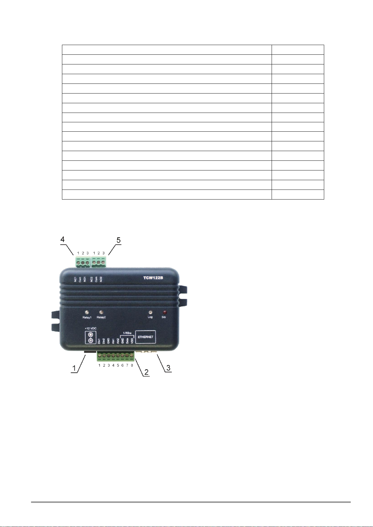
4. Connectors
Inputs and outputs locations are shown below:
* Operating mode is selected by jumper DI1/DI2 - closed for “dry contact” and open for “logic
level”. By default jumpers are closed.
5. LED indicators
The following indicators show the status of the controller:
Relay1/Relay2 (green) – these LEDs are illuminated whenever the corresponding relay is
activated (the NO contact is closed and the NC contact is open);
Connector 1 – Power - central positive
Connector 2, Pin1 - Digital input 1 (Din1)*
Connector 2, Pin2 - Digital input 2 (Din2)*
Connector 2, Pin3 - Ground
Connector 2, Pin4 - Analog input 1 (Ain1)
Connector 2, Pin5 - Analog input 2 (Ain2)
Connector 2, Pin6 - Ground
Connector 2, Pin7 – 1-Wire data
Connector 2, Pin8 – 1-Wire power supply
Connector 3 – Ethernet - RJ45
Connector 4, Pin1 – NC Relay1
Connector 4, Pin2 – COM Relay1
Connector 4, Pin3 – NO Relay1
Connector 5, Pin1 – NC Relay2
Connector 5, Pin1 – COM Relay2
Connector 5, Pin1 – NO Relay2
Sts (red) – flashes when the main program of controller is executed;
Log (yellow) – indicates that somebody is logged via WEB interface;
TCW122B-WD_R2 ( Firmware version 2.xx ) Page 2

Link (green) – located on the Ethernet connector, indicates that the device is connected to
the network;
Act (yellow) – located on the Ethernet connector, flashes when activity is detected on the
network.
6. Powering
TCW122B-WD is designed to be supplied by adapter SYS1421-0612-W2E or similar, intended for
use in the conditions of overvoltage category II, and priorly assessed for compliance with safety
requirements. The power supply equipment shall be resistant to short circuit and overload in secondary
circuit.
When in use do not position the equipment so that it is difficult to operate the disconnecting
device.
7. Environment information
This equipment is intended for use in a Pollution Degree 2 environment, at altitudes up to 2000
meters.
When the controller is a part of a system, the other elements of the system shall comply with the
EMC requirements and shall be intended for use in the same ambient conditions.
8. Safety
This device must not be used for medical, life saving purposes or for any purpose where its failure
could cause serious injury or the loss of life.
To reduce the risk of fire, only flexible stranded wire, with cross section 0.5mm² or larger for
wiring of digital and analog inputs and relay output of the device should be used.
To avoid electric shock and fire hazard, do not expose this product to liquids, rain, or moisture.
Objects filled with liquids, such as vases, should not be placed on this device.
There is a risk of overheating (damage) of controller, if recommended free spaces to adjacent
devices are not ensured. Joint part with external component shall have space for attachment/removal of
the cable after installation.
Teracom does not guarantee successful operation of the product if the product was used under
conditions deviating from the product specifications.
To ensure that the device works correctly follow the steps below:
ensure that the device is installed correctly, refer this user manual;
log in to the devices via browser program;
make proper set up;
set up the digital inputs to work in “dry contact” mode;
short the “Din1” and “GND”;
install sensor TSH1XX or TST1XX on 1-Wire bus;
go to “Monitoring page” of WEB interface – proper parameters value should be displayed in
the same time flashing “STS” led should indicate the proper operation.
If the equipment is used in a manner not specified by the manufacturer, the protection provided
by the equipment may be impaired.
In no event will Teracom Ltd. be responsible or liable for indirect or consequential damages
resulting from the use or application of this equipment.
TCW122B-WD_R2 ( Firmware version 2.xx ) Page 3
9. Maintenance
Upon completion of any service or repairs to the device or once per year, safety check must be
perform to determine that this product is in proper operating condition.
Clean the device only with dry cloth. Do not use a liquid cleaner or an aerosol cleaner. Do not use
a magnetic/static cleaning device (dust remover) or any kind of abrasive materials to clean the device.
10. Installation
This device must be installed by qualified personnel.
This device must not be installed directly outdoors.
Installation consists of mounting the device, connecting to an IP network, connecting inputs and
outputs, providing power and configuring via a web browser.
TCW122B-WD can be wall or flat, not flammable surface mounted, in a clean and dry location
room. Ventilation is recommended for installations where ambient air temperature is expected to be
high.
Mount the device to a wall by using two plastic dowels 8x60mm (example Würth GmbH 0912
802 002) and two dowel screws 6x70mm (example Würth GmbH 0157 06 70). Attach the screws to the
surface vertically. See Appendix-A, fig. 1 for mechanical details.
Maintain spacing from adjacent equipment. Allow 50 mm of space on all sides, as shown on fig.2
in Appendix A, this provides ventilation and electrical isolation.
11. Configuration
Please follow the steps below for proper installation :
1. Mount the controller in a dry and ventilated place.
2. Connect the Ethernet port to a 10/100MB Ethernet network. For direct connection to a PC use
a “crossover” cable.
3. Connect the I/O pins of the controller according to the required application.
4. Connect the power supply.
If the red LED (STS) blinks, the main program of controller is executed. By default TCW122B-WD
comes with the following network settings:
IP address: 192.168.1.2, Subnet Mask: 255.255.255.0, Default Gateway: 192.168.1.1
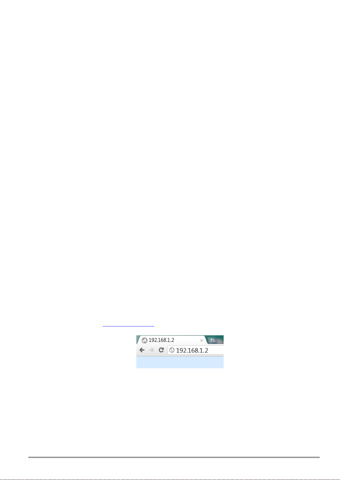
Communication with TCW122B-WD can be established by assigning a temporary IP address to the
computer. This address should be in the same network (for example 192.168.1.3). To get access to the web
interface, you should type http://192.168.1.2 into the browser.
If the network settings are correct, the “Login” page will appear.
The web based interface allows configuration, monitoring and control. Recommended browser is
Internet Explorer at 1024x768 resolutions.
11.1 Login page
After opening the Login page, authorization data must be entered (by default username=admin ,
password=admin). It is recommended to change the username and password to prevent unauthorized
access to the controller.
TCW122B-WD_R2 ( Firmware version 2.xx ) Page 4
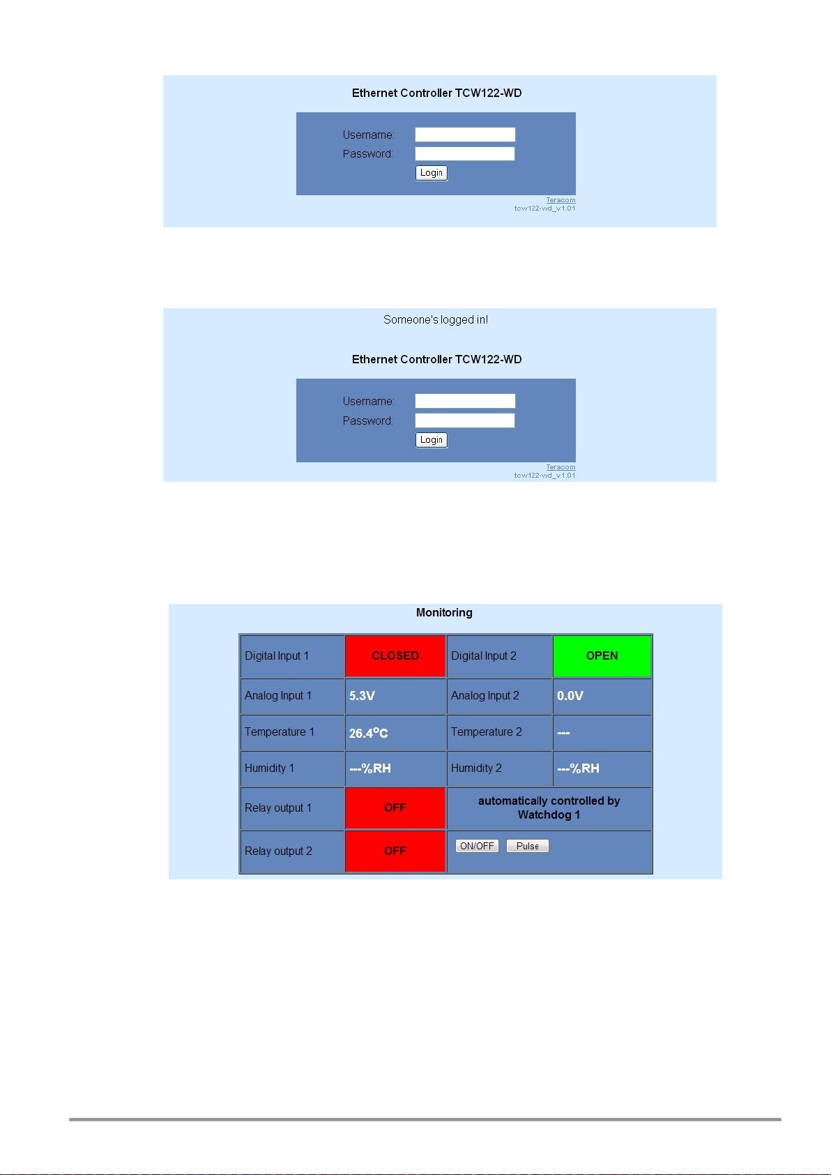
The controller supports one active session – only one user can operate the device. If another user
tries to login, the message “Someone’s logged in” appears:
The active session will be terminated automatically, if the current user stays inactive for 2 minutes.
11.2 Monitoring page
After successful authorization, the “Monitoring” page appears:
The “Monitoring” page provides information about the state of the relays and digital inputs, values of
analog voltages (applied on analog inputs), temperature and humidity.
The state of the relay can be changed by appropriate “ON/OFF” button. To change the state of relay
for a while “Pulse” button should be pressed. Duration of the pulse is specified in “Pulse Duration” field of
“I/O Setup” page.
11.3 I/O setup page
I/O settings can be made here.
TCW122B-WD_R2 ( Firmware version 2.xx ) Page 5
 Loading...