

Teracom TCW122B-RR User Manual


1. Short description
TCW122B-RR is a remote relay control module with an embedded WEB server for setup. The device
has two digital inputs and two relays, with normally open and normally closed contacts.
TCW122B-RR can works in two modes – “Client” or “Server”. The “Client” sends periodically the
status of its digital inputs to the “Server”. As an answer, the “Server” returns its digital inputs
status. Activating the input of “Client” switches on the relay of “Server” and vice versa. This
configuration is used to control remote devices without a browser or to extend a digital signal to
a remote location on the network.
2. Features
• Password protected web-based configuration;
• 2 digital input with "logic level" and "dry contact" modes;
• 2 relays with NO and NC contacts;
• Encrypted communication protocol;
• Device ID filtering;
• Manual or DHCP network configuration;
• Removable terminal connectors - separated for inputs and outputs;
• Autonomous operation;
• Remote firmware update.
3. Specifications
• Physical characteristics
Dimensions: 107 x 72 x 32 mm
Weight: 110 g
• Environmental limits
Operating тemperature range: -20 to 55°C
Storage temperature range: -25 to 60°C
Operating relative humidity range: 5 to 85% (non-condensing)
• Warranty
Warranty period: 3 years
• Power requirements
Input Voltage: 10 to 14 VDC
Input Current: 200 mA @ 12 VDC (with both relays ON)
• Ethernet connectivity
10 Mbit/s transfer rate
Half-duplex mode only
Auto-negotiation not supported
• Digital inputs
Isolation: Non isolated
Mode: Dry contact or Logic level
Maximum input voltage: +5.5VDC
Minimum input voltage for high logic level: +2.5VDC
Maximum input voltage for low logic level: +0.8VDC
Sampling rate: 10mS
Digital filtering time interval: 30mS
TCW122B-RR_R2.4 -March 2019 Page 1
• Relay outputs
Type: Form C (N.O. and N.C. contacts)
Contact current rating: 3 A @ 24 VDC/30 VAC (resistive load)
Initial insulation resistance: 100 mega-ohms (min.) @ 500 VDC
Mechanical endurance: 10 000 000 operations
Electrical endurance: 100 000 operations @ 3 A resistive load
Contact resistance: 50 milli-ohms max. (initial value)
Minimum pulse output: 1 Hz at rated load
• Internal FLASH memory
Endurance: 100 000 cycles (Every relay status and settings change is a memory cycle.)
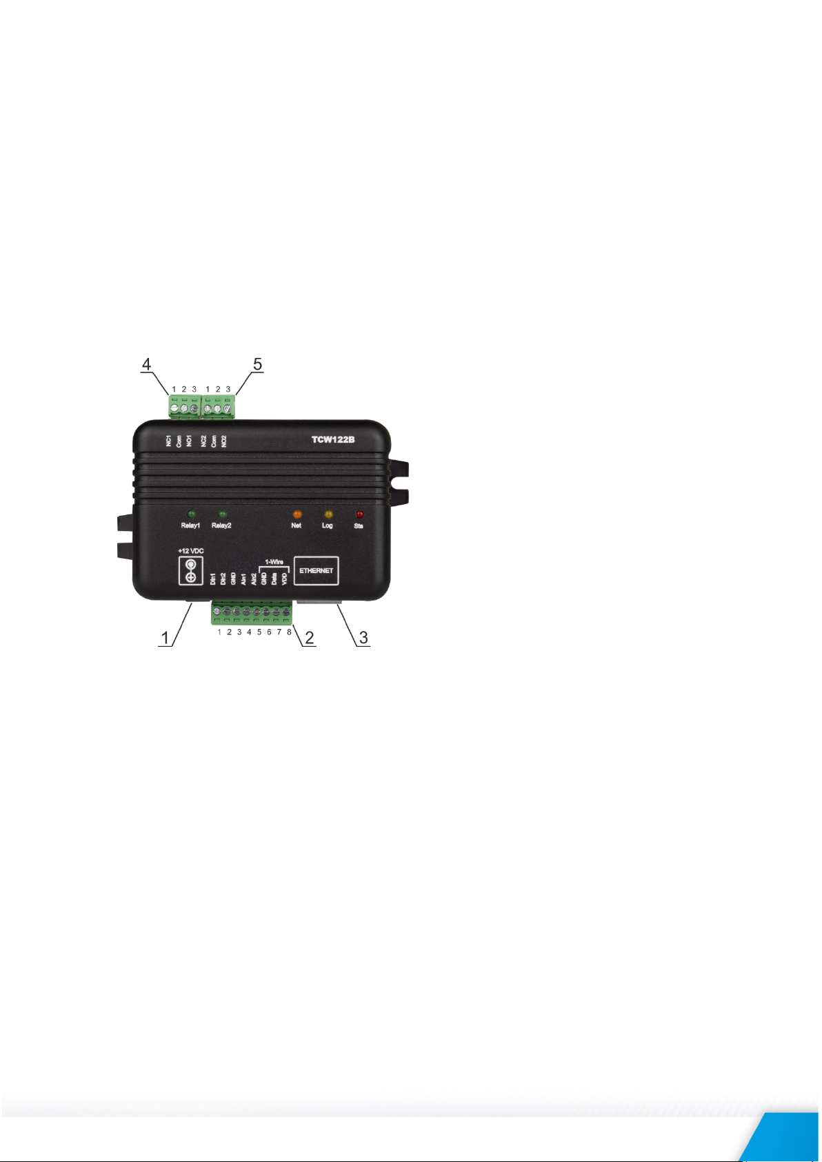
4. Connectors
Inputs and outputs locations are shown below:
Connector 1 – Power - 2.1x5.5mm connector,
central positive
Connector 2, Pin1 – Digital input 1 (Din1)*
Connector 2, Pin2 – Digital input 2 (Din2)*
Connector 2, Pin3 – Ground
Connector 2, Pin4 – Not used
Connector 2, Pin5 – Not used
Connector 2, Pin6 – Ground
Connector 2, Pin7 – Not used
Connector 2, Pin8 – Not used
Connector 3 – Ethernet - RJ45
Connector 4, Pin1 – NC Relay1
Connector 4, Pin2 – COM Relay1
Connector 4, Pin3 – NO Relay1
Connector 5, Pin1 – NC Relay2
Connector 5, Pin1 – COM Relay2
Connector 5, Pin1 – NO Relay2
* Operating mode is selected by jumper DI1/DI2 - closed for “dry contact” and open for “logic
level”. By default, jumpers are closed.
5. LED indicators
The following indicators show the status of the controller:
• Relay1/Relay2 (green) – these LEDs are illuminated whenever the corresponding relay
is activated (the NO contact is closed and the NC contact is open);
• Sts (red) – flashes when the main program of the controller is executed;
• Log (yellow) – ON when somebody is logged via the WEB interface, flashes on 2
seconds when the client and server are connected;
• Net (green/red) – red when the device is linked, yellow when there is an activity.
6. Powering
TCW122B-RR is designed to be supplied by adapter SYS1421-0612-W2E or similar, intended for use
in the conditions of overvoltage category II, and priorly assessed for compliance with safety
requirements. The power supply equipment shall be resistant to short circuit and overload in the
secondary circuit.
TCW122B-RR_R2.4 -March 2019 Page 2

When in use do not position the equipment so that it is difficult to disconnect the device from the
power supply.
7. Installation
This device must be installed by qualified personnel.
This device must not be installed directly outdoors.
The installation consists of mounting the device, connecting to an IP network, connecting inputs
and outputs, providing power and configuring via a web browser.
TCW122B-RR can be wall or flat, not flammable surface mounted, in a clean and dry location room.
Ventilation is recommended for installations where the ambient air temperature is expected to be
high.
Mount the device to a wall by using two plastic dowels 8x60mm (example Würth GmbH 0912
802 002) and two dowel screws 6x70mm (example Würth GmbH 0157 06 70). Attach the screws
to the surface vertically. See Appendix-A, fig. 1 for mechanical details.
Maintain spacing from adjacent equipment. Allow 50 mm of space on all sides, as shown in fig.2 in
Appendix A, this provides ventilation and electrical isolation.
8. Configuration
Please follow the steps below for proper installation :
1. Mount the controller in a dry and ventilated place.
2. Connect the Ethernet port to a 10/100MB Ethernet network. For direct connection to
a PC using a “crossover” cable.
3. Connect the I/O pins of the controller according to the required application.
4. Connect the power supply.
If the red LED (STS) blinks, the main program of the controller is executed. By default TCW122B-RR comes
with the following network settings:
IP address: 192.168.1.2, Subnet Mask: 255.255.255.0, Default Gateway: 192.168.1.1
Communication with TCW122B-RR can be established by assigning a temporary IP address to the
computer. This address should be on the same network (for example 192.168.1.3). To get access
to the web interface, you should type http://192.168.1.2 into the browser.
If the network settings are correct, the “Login” page will appear.
The web-based interface allows configuration, monitoring, and control.
8.1. Login page
After opening the Login page, authorization data must be entered (by default username=admin,
password=admin). It is recommended to change the username and password to prevent
unauthorized access to the controller.
TCW122B-RR_R2.4 -March 2019 Page 3
 Loading...