

Teracom TCW112-CM User Manual


1. Short description
TCW112-CM is a remote environmental monitoring board, which is designed to work in IP-based
networks. It has 1 digital and 1 analog input, 1-Wire interface and 1 relay output. It can be managed
by WEB interface and/or SNMP programs.
The relay can be activated either remotely (WEB, SNMP etc.) or locally - from the status of
monitored parameter (temperature, humidity, analog voltage and dry contact). Only one parameter
can manage the relay at the same time, but for every parameter can be sent an e-mail if it goes
outside of the previously predefined range.
2. Features
10 Mb Ethernet connectivity;
Password protected, web-based configuration and control;
1 digital input with " dry contact" and "logic level" modes;
1 analog input with 0 to 60VDC range;
1 relay with NO and NC contacts;
Long 1-Wire support for 1 temperature (TST1XX) or temperature/humidity (TSH2xx)
sensor;
SNMP v.1;
SNMP traps sending for alert conditions;
E-mail sending for alert conditions;
SMTP with authentication (SSL/TLS is not supported);
HTTP and SNMP port changing;
HTTP and XML API commands;
Remote firmware update.
3. Specifications
Physical characteristics
Dimensions: 72 x 50 x 18 mm
Weight: 45 g
Environmental limits
Operating тemperature range: -20 to 55°C
Storage temperature range: -40 to 85°C
Operating relative humidity range: 5 to 85% (non-condensing)
Warranty
Warranty period: 3 years
Power requirements
Input Voltage: 10 to 14 VDC
Input Current: 120 mA @ 12 VDC (with activated relay)
Digital input
Isolation: Non isolated
Mode: Dry contact or Logic level
Maximum input voltage: +5.5VDC
Minimum input voltage for high logic level: +2.5VDC
Maximum input voltage for low logic level: +0.8VDC
TCW112-CM-R3.2 - March 2018 Page 1

Sampling rate: 10mS
Digital filtering time interval: 30mS
Analog input
Isolation: Non isolated
Type: Single ended
Resolution: 10 bits
Mode: Voltage
Input Range: 0 to 60 VDC
Accuracy: ±1%
Sampling Rate: 37.6mS per channel (averaged value of 64 samples)
Input Impedance: 1 mega-ohms (min.)
Supply voltage for analog sensor (+VA): 5.0 ± 0.1
Maximum output current for analog sensor (+VA): 0.1A
Relay output
Type: Form C (N.O. and N.C. contacts)
Contact current rating: 3 A @ 24 VDC/30 VAC (resistive load)
Initial insulation resistance: 100 mega-ohms (min.) @ 500 VDC
Mechanical endurance: 10 000 000 operations
Electrical endurance: 100 000 operations @ 3 A resistive load
Contact resistance: 50 milli-ohms max. (initial value)
Minimum pulse output: 1 Hz at rated load
1-Wire interface
Output voltage (+VW): 5.3 ± 0.2 VDC
Maximum output current (+VW): 0.2 A
Internal FLASH memory
Endurance: 100 000 cycles (Every relay status and settings change is a memory cycle.)
TCW112-CM-R3.2 - March 2018 Page 2
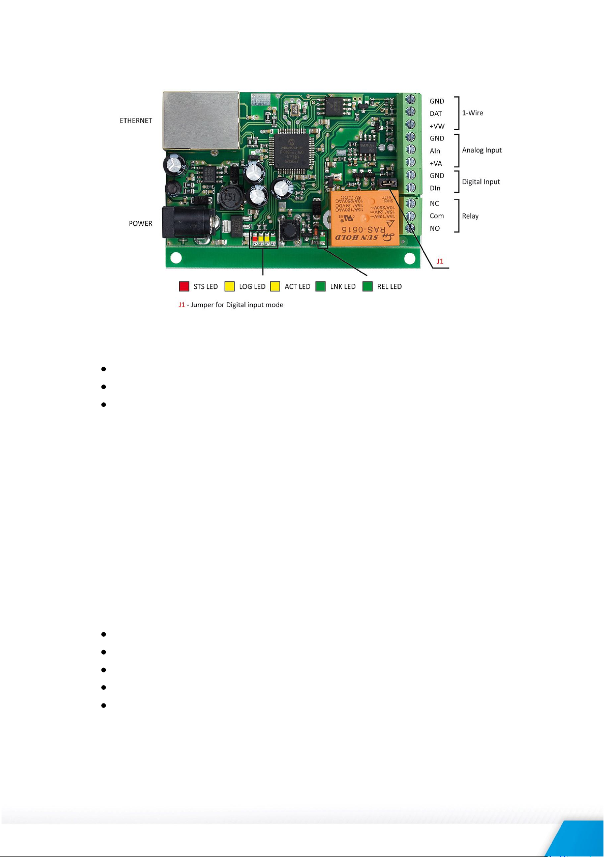
4. Connectors and LED’s
The location of the connectors and LED’s are shown below:
4.1 Connectors
The device has following connectors:
Power – 2.1x5.5mm connector, central positive;
Ethernet - RJ45 connector;
Screw terminals:
- GND ground for 1-Wire sensor;
- DAT data input/output of 1-Wire sensor;
- +VW power supply for 1-Wire sensor;
- GND ground for analog input;
- AIn analog input;
- +VA power supply for analog sensors;
- GND ground for digital input;
- DIn digital input, operates either in “dry contact” mode (J1 is closed) or
“logic level” mode (J1 is open);
- Relay normal open and normal closed contacts are available.
4.2 LED indicators
The following LED’s show the status of the controller:
STS (red) – flashes when the main program of the controller is executed;
LOG (yellow) – indicates that somebody is logged via WEB interface;
ACT (yellow) – flashing when there is an activity;
LNK (green) – ON when the link is up, OFF when no or bad connection;
REL (green) – indicates that the relay is activated.
TCW112-CM-R3.2 - March 2018 Page 3

5. Powering
TCW112-CM is designed to be supplied by adapter SYS1421-0612-W2E or similar, intended for use
in the conditions of overvoltage category II, and priorly assessed for compliance with safety
requirements. The power supply equipment shall be resistant to short circuit and overload in the
secondary circuit.
When in use do not position the equipment so that it is difficult to disconnect the device from the
power supply.
6. Installation
The installation consists of mounting the device, connecting to an IP network, connecting inputs and
outputs, providing power and configuring via a web browser.
This device must be installed by qualified personnel.
This device must not be installed directly outdoors.
This device should be mounted in a clean and dry location room. Ventilation is recommended for
installations where the ambient air temperature is expected to be high.
The device should be installed in the not flammable box. See Appendix-A, fig. 1 for mechanical
details. Maintain spacing from adjacent equipment. Allow 50 mm of space on all sides, as shown in
fig.2 in Appendix A. This provides ventilation and electrical isolation.
7. Configuration
Please follow the steps below for proper installation:
1. Mount the controller in a dry and ventilated place.
2. Connect the Ethernet port to a 10/100MB Ethernet network. For direct connection to a
PC using a “crossover” cable.
3. Connect the I/O pins of the controller according to the required application.
4. Connect the power supply.
If the red LED (STS) blinks, the main program of the controller is executed. By default TCW112-CM is
delivered with the following network settings:
IP address: 192.168.1.2, Subnet Mask: 255.255.255.0, Default Gateway: 192.168.1.1
Communication with TCW112-CM can be established by assigning a temporary IP address to the
computer. This address should be on the same network (for example 192.168.1.3). To get access to
the web interface, you should type http://192.168.1.2 into the browser address field.
If the network settings are correct, the “Login” page will appear.
The web-based interface allows configuration, monitoring, and control.
TCW112-CM-R3.2 - March 2018 Page 4
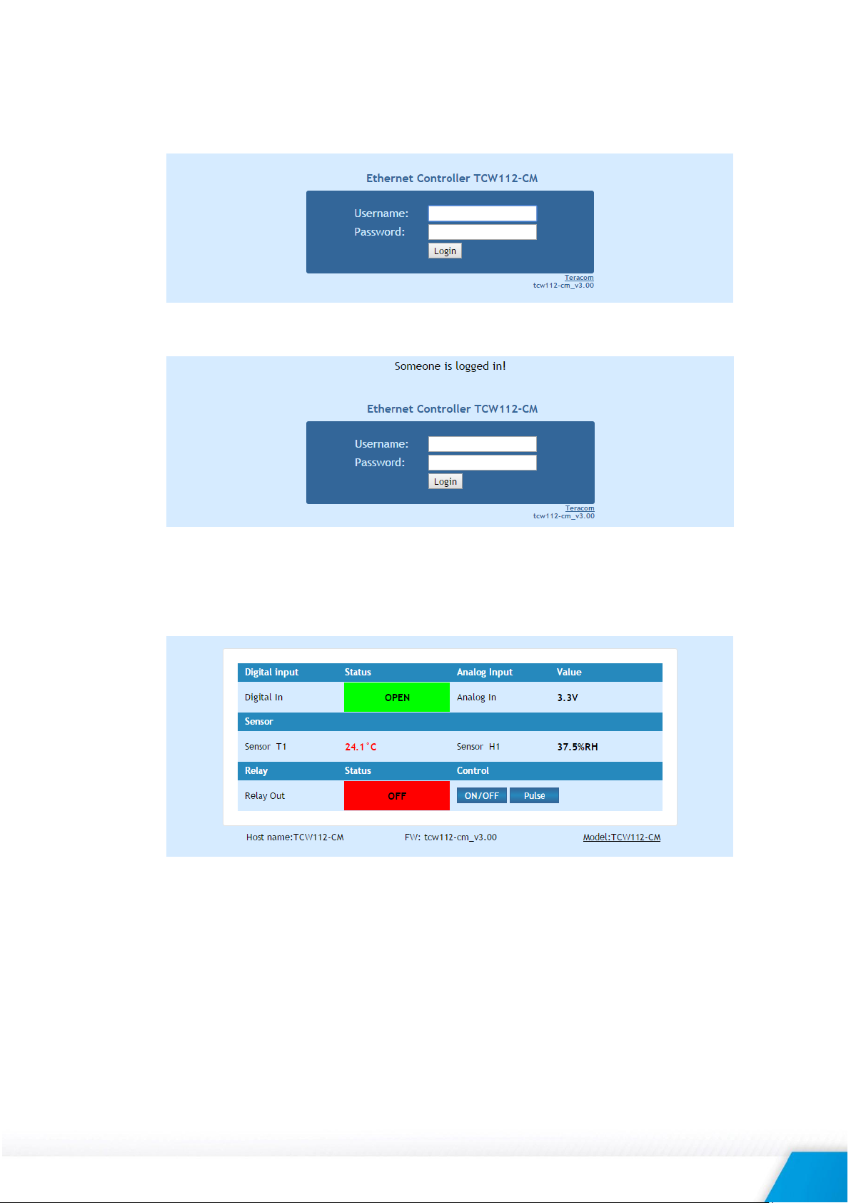
7.1 Login page
After opening the Login page, authorization data must be entered (by default username=admin,
password=admin). It is recommended to change the username and password to prevent
unauthorized access to the controller.
The controller supports one active session – only one user can operate the device. If another
user tries to log in, the message “Someone’s logged in” appears:
The active session will be terminated automatically if the current user stays inactive for 2
minutes.
7.2 Monitoring page
After successful authorization, the “Monitoring page” appears:
The “Monitoring page” provides information about the state of the digital and analog input, relay
status, temperature, and humidity (if a sensor is connected).
Digital input can be used for monitoring the state of discrete devices – motion sensor, door contact,
relay contact, alarm output etc. The digital input is not galvanic isolated. One side of the contact is
connected to “Digital In” and another side is connected to “GND” pins. Digital input is sampled
every 30mS. The change of input status is considered valid if the same value is read in seven
consecutive samples.
TCW112-CM-R3.2 - March 2018 Page 5
 Loading...