

Teracom TCW110 User Manual
Ethernet controller TCW110
Users manual
1. Short description
TCW110 is a multifunctional device for remote monitoring and management. It is an
Ethernet based controller, which is designed to work in IP-based networks and managed by
WEB interface or SNMP programs. Its I/O interface - relay output, analog and digital input is
suitable for solving specific problems in various fields such as remote control, alarm systems,
industrial process automation, control and management of computer networks etc. High
precision digital temperature sensor is option.
2. Features
• 10 Mbit Ethernet connectivity
• Password protected, web based configuration and control
• 1 digital input, 1 analog input
• 3A/24VDC Relay output
• Sending SNMP Traps messages under certain conditions
• Optional high precision temperature sensor
• Sending E-mail messages under certain conditions
• Relay restart on ping/echo timeout
• SNMP v.1, SMTP, ICMP, VLAN support
• TCW110 can be used as standalone device or as a part of control and monitoring
system
• MAC Address filtering
• Remote FTP firmware update
3. Technical parameters
Operating temperature
, °C
0 ÷ 40
Maximum
low level input voltage
, V 0.8
Supply Voltage, VDC
Weight, g
Dimensions, mm
12
40
72 x 50 x 18
Storage temperature , °C
Analog input range, VDC 0 ÷ 100
Minimum high level input voltage, V
Maximum input voltage for digital inputs, V
Max. switchable current (at 220 VAC) , А
Max. switchable voltage, VAC/VDC
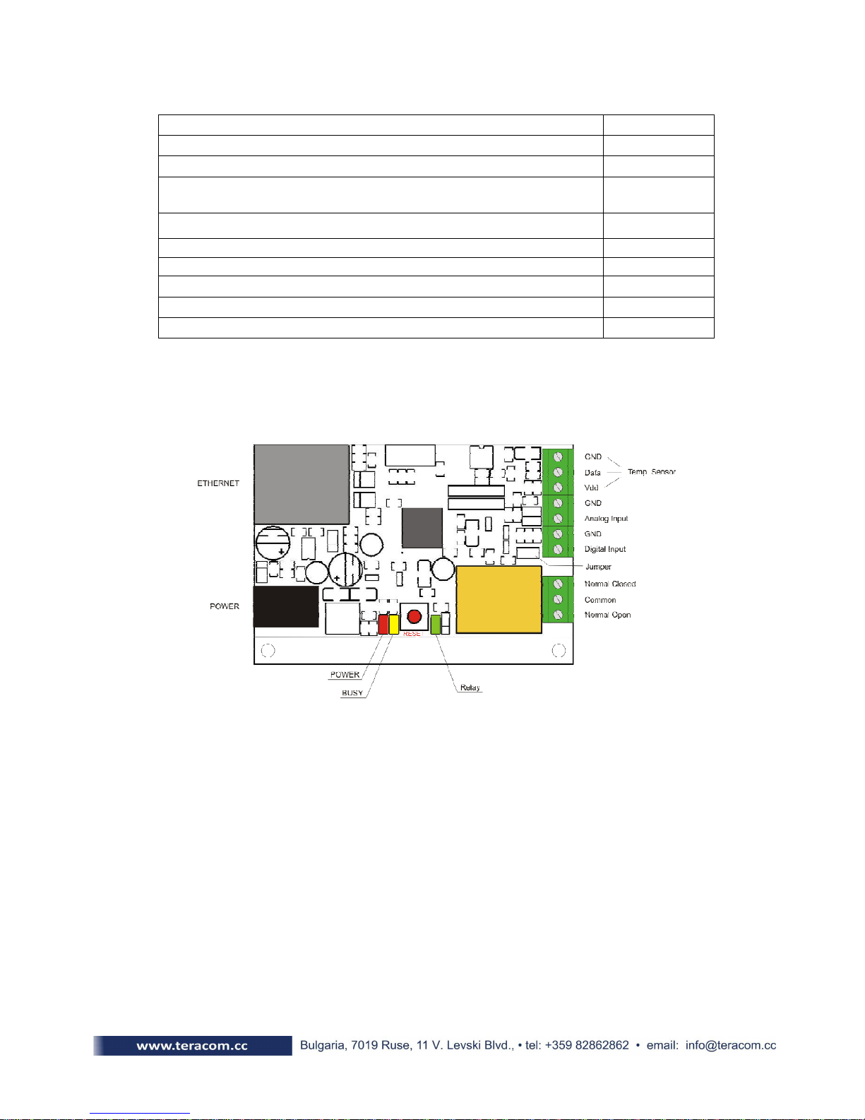
4. Connectors & LED indicators
The location of the connectors is shown in the figure below ;
-40 ÷ 85
2.5
5.5
3
250/110
The following indicators show the status of the controller :
• Relay (green) – this LED is illuminated whenever the relay is closed (the Normally
Open contact is closed and the Normally Closed contact is open);
• Power (red) – this LED flashes when the power supply is turned on;
• Busy (yellow) – this LED indicates that someone is connected to the controller
through web interface;
• Link (green) – this LED is located on the Ethernet connector. It indicates that the
device is connected to the network ;
• Act (yellow) – this LED is located on the Ethernet connector. It flashes when activity
is detected on the network.
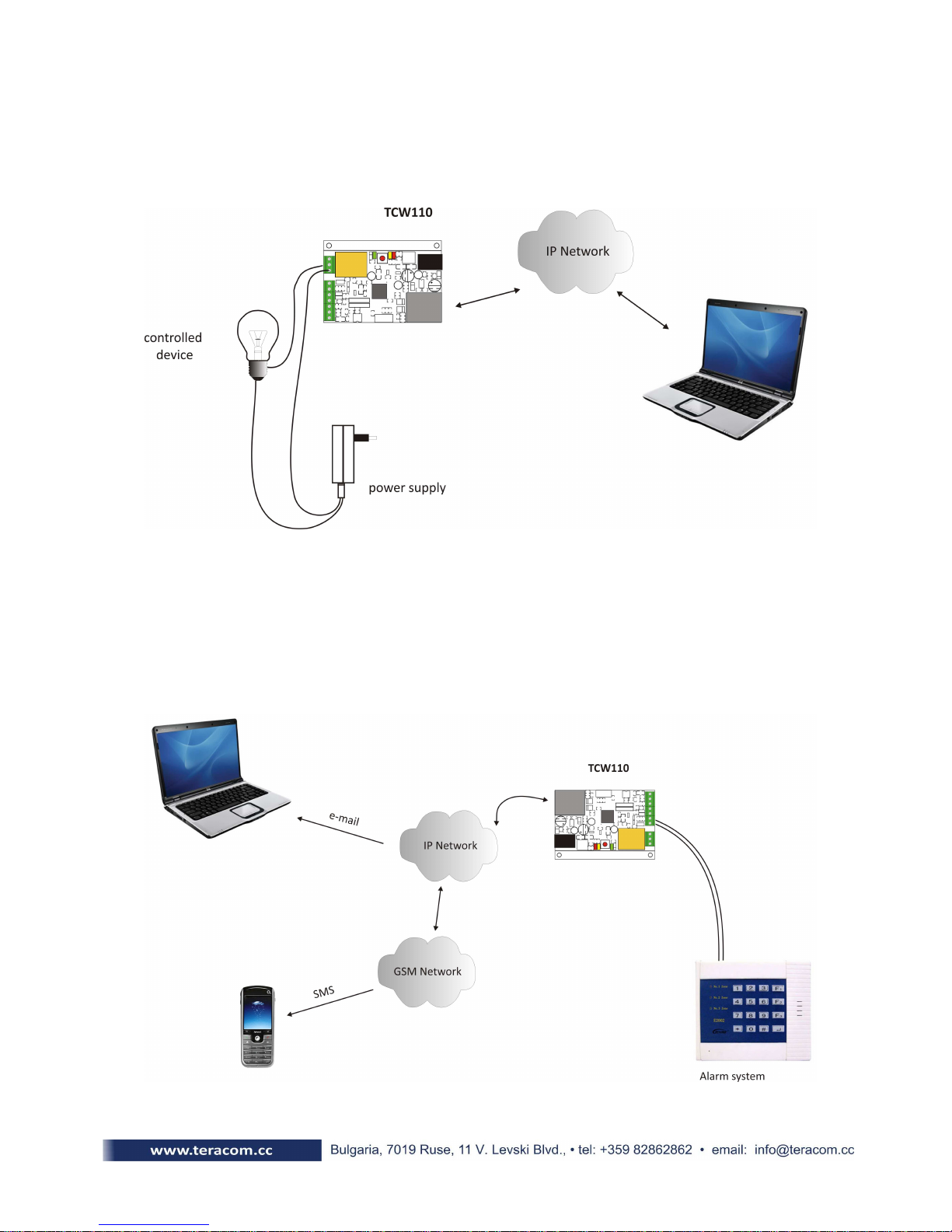
5. Application examples
5.1 Remote control
The controlled device is connected in series with the relay contact. Users can operate
TCW110 using a web browser or by using custom SNMP applications.
5.2 Remote monitoring
A relay output from the monitored device is connected to digital input of TCW110.
When an event occurs – the controller sends an E-mail message to a predefined e-mail
address. SNMP Trap message is sent if custom SNMP monitoring software is used.
6. Installation
Please follow the steps below for proper installation :
1. Mount the controller in a dry and ventilated place.
2. Connect the Ethernet port to a 10/100 Base T Ethernet connection. For direct
connection to a PC use a “crossover” cable.
3. Connect the I/O pins of the controller according to the required application.
4. Connect the power supply.
If the Power LED is blinking, it indicates that the power supply is OK. By default TCW110
comes with the following network settings:
IP:192.168.1.2 , Subnet Mask: 255.255.255.0 , Default Gateway: 192.168.1.1
Communication with TCW110 may be established by assigning a temporary IP address to
your computer that is on the same network (for example 192.168.1.5). To get access to the web
interface of the controller, you should type the following URL into the browser :
http://192.168.1.2 . If the network settings are correct, the “Login” page will appear.
7. Web-based setup
The web interface allows the TCW110 to be configured, controlled and monitored via web
browser. Recommended programs are Mozilla Firefox, Chrome and Internet Explorer 6 (or higher
version) at 1024x768 resolution.
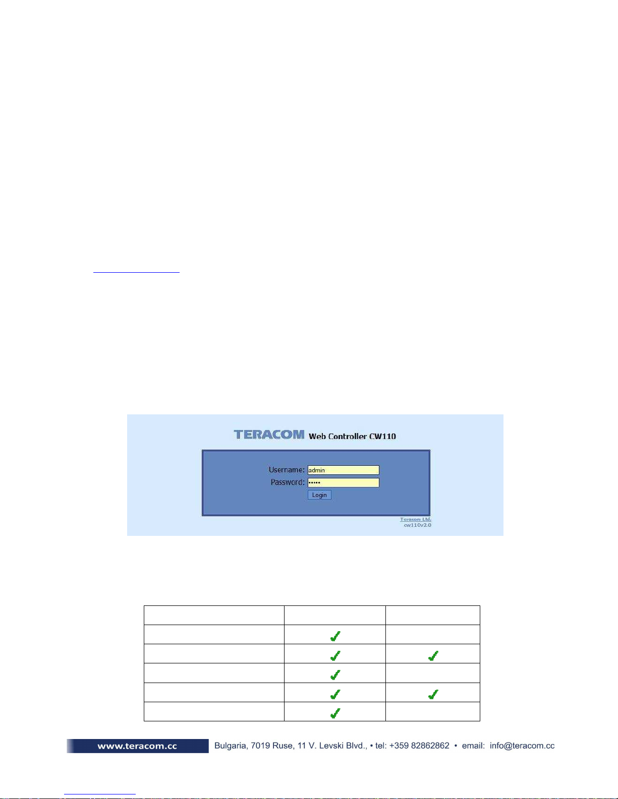
7.1 Login page
After opening the Login page, authorization data must be entered ( by default
username=admin , password=admin). It is recommended to change the username and password
to prevent unauthorized access to the controller.
Depending on the username and password, there are two access levels to the controller user and administrator. This is done to restrict the access to certain functions. Both access levels
are described in table below :
Account Administration
Monitoring
Network Setup
I/O Setup
SNMP Setup
administrator user
 Loading...