

Teracom TCG140 User Manual


TCG140_R1.1 – May 2018 Page 2
1. Short description
TCG140 is a GSM-GPRS remote IO controller. It has 2 digital inputs, 4 analog inputs, digital interfaces
for external sensors and 4 relays. Two of analog inputs can be switched either in a current (0-20mA) or
voltage modes. The relays can be activated either remotely (via SMS or HTTP API command) or locally from the status of the monitored parameter.
TCG140 supports all digital sensors of Teracom.
All monitored parameters and status of relays can be periodically saved in the embedded data logger.
It is also possible to arrange records on any alarm condition.
The controller supports HTTP API for easy M2M communication. The GSM-GPRS remote IO controller
can periodically send data to a remote server or can be polled by the server if data card with public
static IP is used.
2. Features
Quad-bands connectivity;
GPRS data logger with up to 70000 records;
Setup via USB, SMS and HTTP API;
2 digital "dry contact" inputs;
Up to 4 analog inputs with 0 to 10VDC range;
Up to 2 current loop (4-20mA) inputs;
Settable multiplier, offset, and dimension for analog inputs;
4 relays with NO and NC contacts;
1-Wire support for all Teracom sensors;
MODBUS RTU sensors support (optional);
SMS alarm alerts for up to 5 numbers;
Email alarm alerts for up to 5 email recipients;
Single call relay control for up to 5 numbers;
Periodical HTTP post with current status in XML or JSON file to remote server;
Periodical HTTP post with logger data in CVS format to remote server;
HTTP API commands in server mode (with public static IP address data card);
Firmware update over USB or GPRS.
3. Applications
TCG140 is suitable for industrial automation, data acquisition systems, environmental monitoring, local
control of an electrical and non-electrical parameter, building automation etc.:
SCADA
The controller is designed for easy SCADA systems integration. It supports either client or
server mode communication with the dedicated server. In both ways, HTTP protocol is used
with a POST or GET messages.
Stand-alone data logger
The device can be used as a standard data logger with minimum record time as low as 1
minute. The logged data can be periodically uploaded to a dedicated server as CSV file.
Environmental monitoring and control

TCG140_R1.1 – May 2018 Page 3
4. Specifications
Physical characteristics
Dimensions: 158 x 119 x 32 mm
Weight: 470 g
Mounting: wall and DIN rail
Environmental limits
Operating Temperature: -20 to 55°C
Storage Temperature: -40 to 85°C
Ambient Relative Humidity: 5 to 85% (non-condensing)
Standards and Certifications
Safety: EN 60950-1:2006+A11:2009+A1:2010+A12:2011+A2:2013, EN 62311:2008
EMC: EN 55022:2010, EN 55024:2010, EN 61000-3-2:2014, EN 61000-3-3:2013
EN 301489-1 V1.9.2, EN 301489-7 V1.3.1
RFSU: EN 301511 V9.0.2
Green Product: RoHS
Warranty
Warranty period: 3 years
Power requirements
Input Voltage: 10 to 24 VDC
Input Current: 340 mA @ 12 VDC
Cellular interface
Standards: GSM/GPRS
Bands: 850/900/1800/1900 MHz
GPRS multi-slot class: 12, 1~12 configurable
GPRS terminal device class: Class B
Compliant to GSM Phase 2/2+: Class 4 (2W@850/ 900MHz), Class 1 (1W@1800/1900MHz)
SIM card size: Micro
Antenna connector: SMA-F
Analog inputs
Isolation: Non isolated
Type: Single ended
Resolution: 10 bits
Mode (Analog inputs 1 and 2): Voltage
Mode (Analog inputs 3 and 4): Voltage / Current (WEB interface selectable)
Input Range: 0 to 10 VDC, 0 to 20 mA
Accuracy: ±1%
Sampling Rate: 500mS per channel (averaged value of 250 samples)
Input Impedance: 1 mega-ohms (min.)
Built-in resistor for current mode: 410 ohms
Digital inputs
Isolation: Non isolated
Type: Dry contact
Sampling rate: 10mS
Digital filtering time interval: 30mS
Relay outputs
Type: Form C (N.O. and N.C. contacts)
Contact current rating: 3 A @ 24 VDC, 30 VAC (resistive load)

TCG140_R1.1 – May 2018 Page 4
Initial insulation resistance: 100 mega-ohms (min.) @ 500 VDC
Mechanical endurance: 10 000 000 operations
Electrical endurance: 100 000 operations @ 3 A resistive load
Contact resistance: 50 milli-ohms max. (initial value)
Pulse output: 0.1 Hz at rated load
Digital sensor interfaces (1-Wire and RS-485)
Output voltage: 5.0 ± 0.3 VDC
Maximum output current (for both interfaces): 200 mA
Internal FLASH memory
Endurance: 100 000 cycles (Every relay status and settings change is a memory cycle.)
5. Installation
This device must be installed by qualified personnel. The installation consists of mounting the device,
connecting the GSM antenna, connecting inputs and outputs, providing power and configuring via a
web browser. This device must not be installed directly outdoors.
Attention! Before installing the SIM card in the card slot, please ensure that the PIN code is
disabled.
5.1. Mounting
TCG140 should be mounted in a clean and dry location on a not flammable surface. Ventilation is
recommended for installations where ambient air temperature is expected to be high.
Mount the device to a wall by using two plastic dowels 8x60mm (example Würth GmbH 0912
802 002) and two dowel screws 6x70mm (example Würth GmbH 0157 06 70). See Appendix C, fig. 1
for mechanical details.
Maintain spacing from adjacent equipment. Allow 50 mm of space on all sides, as shown in fig.2 in
Appendix C, this provides ventilation and electrical isolation.
For DIN rail mounting, a DIN-RAIL-MOUNT-KIT should be used.
5.2. Connectors
Attention! Disconnect power supply before wiring.
The correct wiring procedure is as follows:
Make sure power is turned off;
Make wiring connections to the terminals;
Apply power.
It is recommended to test and configure TCG140 without any controlled device.
Make sure that wires are properly attached to the terminals and that the terminals are tightened.
Not proper wiring and configuration can cause permanent damage to the controller or the
equipment to which it is connected or both. Inputs and outputs locations are shown below:
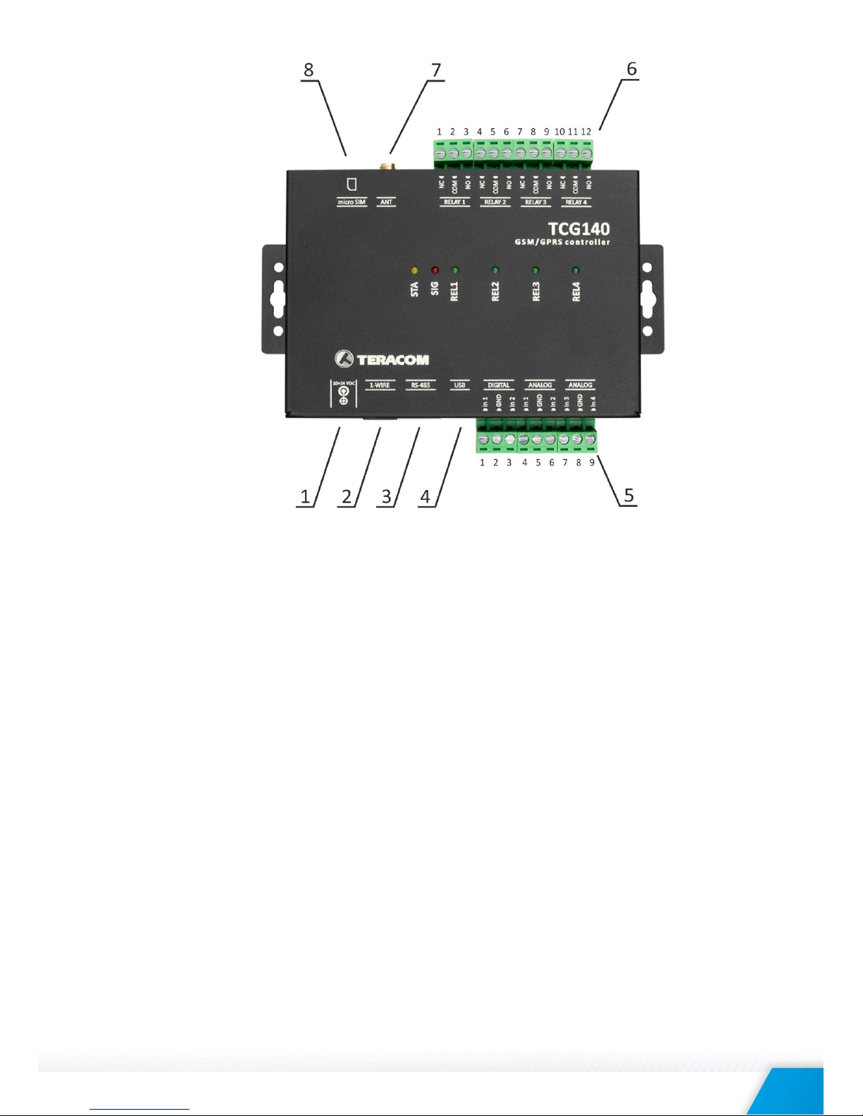
TCG140_R1.1 – May 2018 Page 5
Connector 1
Power - central positive
Connector 5
Pin1 – Digital In 1
Connector 2
Pin1 – GND(most left)
Pin2 – Ground
Pin2 – GND
Pin3 – Digital In 2
Pin3 – 1-Wire data
Pin4 – Analog In 1
Pin4 – 1-Wire GND
Pin5 – Ground
Pin5 – 1-Wire +VDD
Pin6 – Analog In 2
Pin6 – 1-Wire +VDD(most right)
Pin7 – Analog In 3
Connector 3
RS-485
Pin8 – Ground
Pin1 – not connected (most left)
Pin9 – Analog In 4
Pin2 – not connected
Connector 6
Pin1 – NC Relay 1
Pin3 – not connected
Pin2 – COM Relay 1
Pin4 – Line B-
Pin3 – NO Relay 1
Pin5 – Line A+
Pin4 – NC Relay 2
Pin6 – not connected
Pin5 – COM Relay 2
Pin7 – +VDD
Pin6 – NO Relay 2
Pin8 – GND
Pin7 – NC Relay 3
Connector 4
mini USB
Pin8 – COM Relay 3
Pin9 – NO Relay 3
Pin10 – NC Relay 4
Pin11 – COM Relay 4
Pin12 – NO Relay 4
Connector 7
GSM Antenna
Connector 8
SIM card holder
TCG140_R1.1 – May 2018 Page 6
5.2.1. Power supply connection
TCG140 is designed to be supplied by adapter SYS1308-2412-W2E or similar, intended for use in
the conditions of overvoltage category II. The power supply equipment shall be resistant to short
circuit and overload in a secondary circuit.
When in use, do not position the equipment so that it is difficult to disconnect the device from
the power supply.
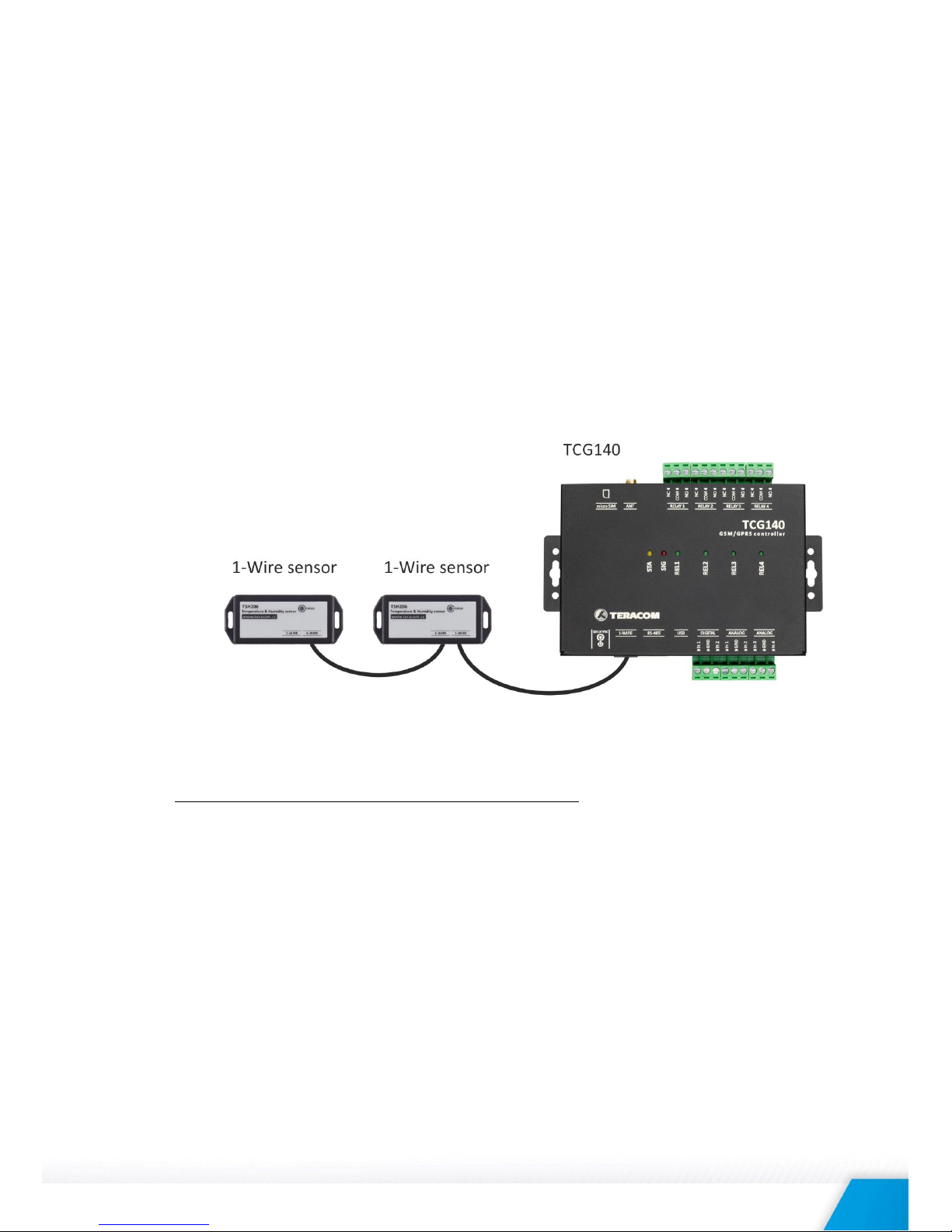
5.2.2. 1-Wire interface
1-Wire is a registered trademark of Maxim Integrated Products, Inc. It is designed to connect
several sensors over a short wiring. It is not suitable for long distances or environments with EMC
interference.
The maximum number of sensors (1-Wire or RS-485) connected to TCG140 is 8.
The device supports temperature and humidity-temperature sensors. Connected sensors are
automatically detected and appropriate dimension is assigned.
It is strongly recommended to use “daisy-chained” (linear topology) for multi-sensors systems:
It is strongly recommended to use only UTP/FTP cables and keep total cable length up to 30m.
Although functionality has been achieved in the longer distance, we cannot guarantee error-free
operation over mentioned wiring length. We recommend reading Maxim’s 1-Wire tips at
http://www.maxim-ic.com/app-notes/index.mvp/id/148.
We guarantee proper operation only with Teracom 1-Wire sensors.
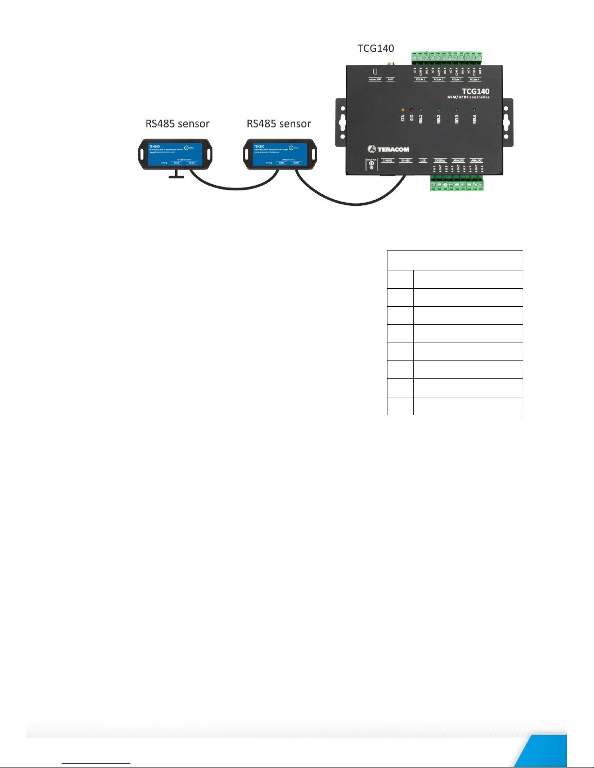
5.2.3. RS-485 interface
RS-485 is a standard for serial communications systems defined by Telecommunications Industry
Association (TIA) and Electronic Industries Alliance (EIA). Implementing the standard,
communication systems can be used effectively over long distances and in electrically noisy
(industrial) environments.
The maximum number of sensors (1-Wire or RS-485) connected to TCG140 is 8.
The device supports temperature and humidity-temperature sensors.
MODBUS RTU protocol specifies that address of the device should be between 1 and 247. The
user should take care of appropriate address settings.
For multi-sensors systems “daisy-chained” (linear topology) should be used:
TCG140_R1.1 – May 2018 Page 7
Interconnections are realized by UTP/FTP cables with RJ-45 connectors. The popular Ethernet
wiring standard ANSI/TIA/EIA T568B is used:
It is recommended to use standard patch cables for LAN
networks.
Special attention should be paid on termination of the bus in
the last sensor.
We recommend keeping total cable length up to 30 m,
although the RS-485 interface works over much longer
distance.
Attention!
Special attention should be paid on termination of the bus.
The last sensor in the chain should have a terminator
installed on the free RJ-45 socket.
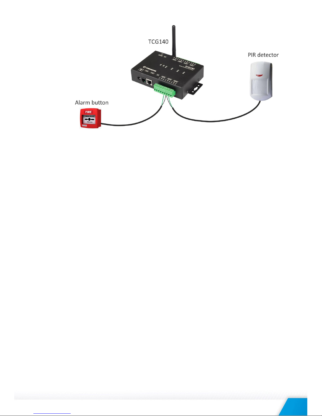
5.2.4. Digital inputs connection
Attention! Digital inputs are NOT galvanic isolated.
The TCG140 digital inputs can be used as “dry contact” only.
The term “dry contact” means that to this input can be connected devices with an open drain or
relay outputs - door contact switch, push button, PIR detector etc.
The following picture illustrates how an alarm button can be connected to a digital input of
TCG140. One side of the contact is connected to “Digital In” while the other side is connected to
“GND” terminal.
Pin# RJ45
1
Orange/White Tracer
2
Orange
3
Green/White Tracer
4
Blue
5
Blue/White Tracer
6
Green
7
Brown/White Tracer
8
Brown
TCG140_R1.1 – May 2018 Page 8
The maximum cable length for a digital input should be up to 30 meters.
5.2.5. Analog inputs connection
Attention! Analog inputs are NOT galvanic isolated.
Analog inputs of TCG140 can be used for monitoring of DC voltage up to 10VDC. They can be
connected directly to sensors and transmitters with such analog output.
The sample rate of analog inputs is
The “Multiplier”, “Offset” and “Dimension” for every analog input gives a possibility to monitor
sensors with analog outputs and see directly the measured parameter.
It is possible to monitor voltages bigger than 10VDC with adding an external resistor in series. For
every 1 mega-ohm, the voltage will be extended with 5.893V. The external resistor should be
with 1% or better accuracy.
To analog inputs 3 and 4 internally can be assigned 410-ohm resistor in parallel of the input. In
this case, the input can accept directly 0-20mA current loop sensors and transmitters.
The switching of the resistor is done by the user interface.
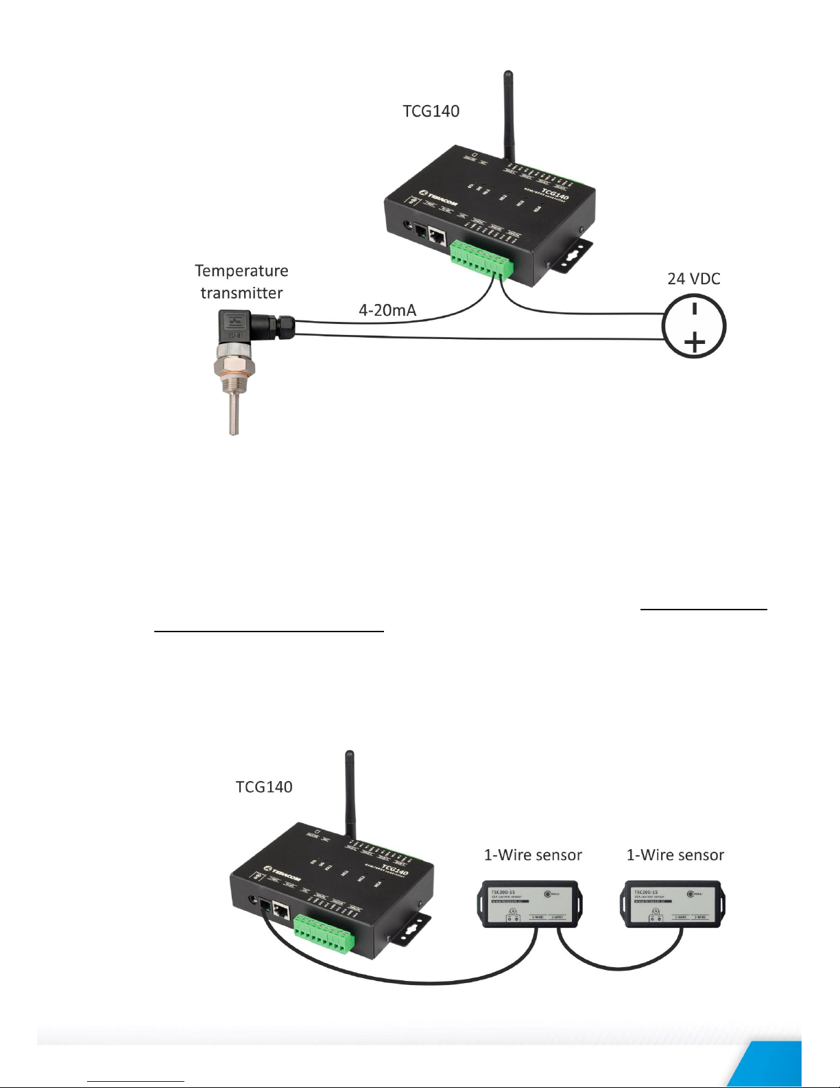
The following picture illustrates how 0-10V analog sensor is connected to the analog input 1 and
0-20mA current loop transmitter is connected to analog input 3. The analog input 3 is in current
mode.
TCG140_R1.1 – May 2018 Page 9
The maximum cable length for an analog input should be up to 30 meters.
5.2.6. Sensors connection
Up to 8 1-Wire sensors can be connected to TCG140 controller. The device supports all Teracom
1-Wire sensors.
1-Wire is a registered trademark of Maxim Integrated Products, Inc. It is designed to connect
several sensors over a short wiring. It is not suitable for long distances or environments with
EMC interference. We recommend reading Maxim’s 1-Wire tips at http://www.maximic.com/app-notes/index.mvp/id/148.
The sensors have three wires – positive voltage (+VDD), ground (GND) and bidirectional data
(Data). The colors of wires for every sensor are specified in its user manual.
It is strongly recommended to use “daisy-chained” (linear topology) for multiple sensors:
TCG140_R1.1 – May 2018 Page 10
“Star” topology can be used only as a last resort for up to 4 sensors and total cable length up to
10 meters.
There are many parameters which determine the maximum length of the wires - type of cable,
the number of sensors, ambient electromagnetic noise and sensor network topology.
It is strongly recommended to use only UTP/FTP cables and keep total cable length up to 30 m.
Although functionality has been achieved in а longer distance, we cannot guarantee error-free
operation over mentioned wiring length.
We guarantee proper operation only with Teracom 1-Wire sensors.
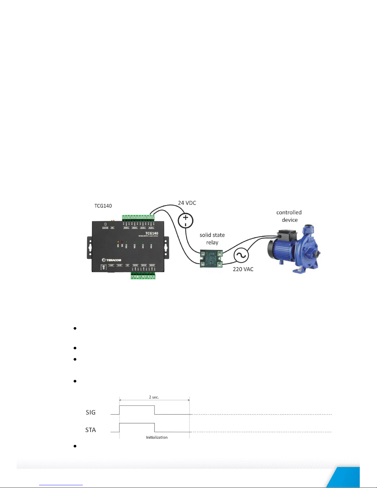
5.2.7. Relays connection
The relay contacts are internally connected directly to the terminal connectors. For all relays
normally open, normally closed and common contacts are available. For loads with higher
switchable current/voltage than specified, an external relay should be used.
When mechanical relays switch inductive loads such as motors, transformers, relays, etc., the
current will arc across the relay contacts each time the contacts open. Over time, this cause
wears on the relay contacts which shorten their life. When switching an inductive load, it is
recommended that relay contact protection devices are used.
6. LED indicators
LED indicators show the status of the controller:
REL1 - REL4 (green) – the LED is ON when the corresponding relay is activated (the NO
contact is connected to COM);
SIG (red) – indicates the status of the device together with STA
STA (yellow) – indicates the status of the device together with SIG.
The following states are displayed:
Controller initialization – after power-on and firmware update SIG and STA turn ON for a
second, after this turn OFF for another second.
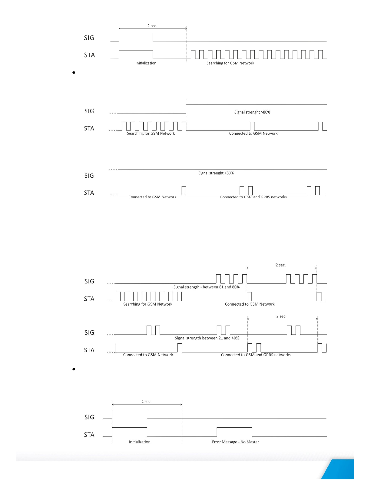
Searching for GSM network – after initialization, SIG is OFF, STA flashes (flash length –
200ms)
TCG140_R1.1 – May 2018 Page 11
Connected to GSM network – after successful connection to a mobile network, STA shows
the type of connection, while SIG shows the signal strength.
STA flashes ones for 200mS in period of 2S – there is GSM connection only;
STA flashes twice for 200mS in a period of 2S – there is GSM and GPRS connection.
In the same time SIG has 5 states:
SIG flashes 1 time in period of 2S – signal strength is between 0 and 20%;
SIG flashes 2 times in period of 2S – signal strength is between 21 and 40%;
SIG flashes 3 times in period of 2S – signal strength is between 41 and 60%;
SIG flashes 4 times in period of 2S – signal strength is between 61 and 80%;
SIG is solid ON – signal strength is between 81 and 100%;
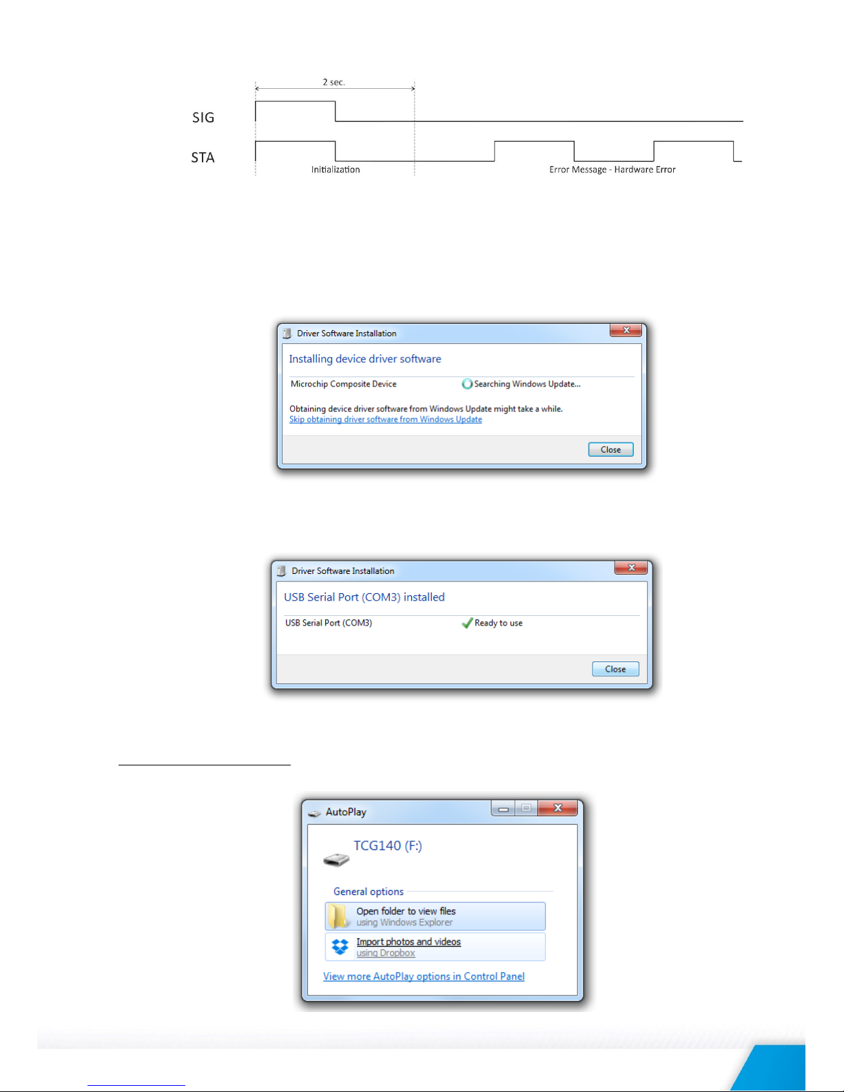
Error message – in case of error after initialization, SIG will stay solid OFF, STA will flash
showing the type of error.
STA flashes ones for 1S – master phone number is not set;
STA flashes permanently for 1S in a period of 2S – permanent hardware error.
TCG140_R1.1 – May 2018 Page 12
7. Initial setup via USB
The initial setup of TCG140 is done with a computer running Windows 7 or newer Microsoft Windows
operating system. After power-up, the controller should be connected to the computer with USB
cable. Once the USB cable is connected, the operating system automatically starts to install the drivers
for the communication with the device. The following message appears:
The following drivers will be installed:
- Microchip composite device
- USB serial port driver
If for some reason the USB serial port driver cannot be installed automatically, it must be installed
manually. The driver can be downloaded from the TCG140 product page at
www.teracomsystems.com. After successful driver installation, the device will be recognized as Mass
storage, the following window appears on the screen:
TCG140_R1.1 – May 2018 Page 13
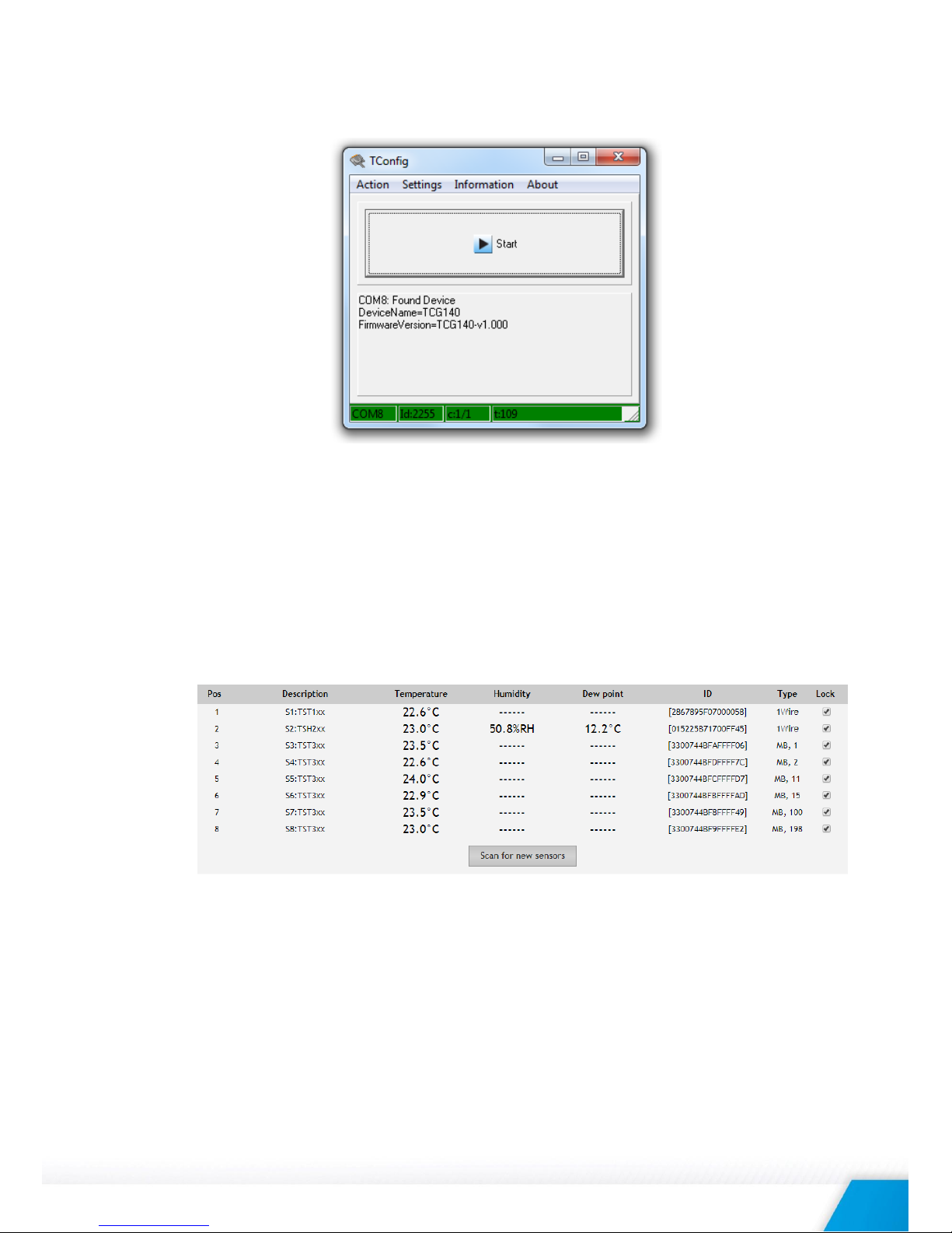
The only file stored on the mass storage is a tool called “TConfig”. This tool enables the communication
between the TCG140 and PC. After starting the TConfig tool, the following program will appear:
Pressing the “Start” button will start your web browser and display the Monitoring page of your
TCG140.
7.1. Monitoring page
Monitoring page displays the current I/O state of TCG140. The page has 4 sections – “Sensors”,
“Digital inputs”, “Analog inputs” and “Relays”.
For every parameter (sensor, input, relay) there is a description of up to 15 characters. The default
descriptions can be changed in “Setup-Input/Output” menu.
The Monitoring page is automatically refreshed on 1 second.
7.1.1. Sensors section
All detected 1-Wire sensors are shown in this section. Sensor detection is made either after
power-on or by pressing “Scan for new sensors” button. All found sensors are shown in
ascending order refer their unique ID number. For every sensor, there are a description, value,
and ID information.
All sensors have value only in the Value 1 column. Only TSH2xx temperature and humidity
sensors have the 2nd parameter shown in Value 2 column.
It is possible to lock sensors in a specific position. To do this all sensors should be added one by
one. After every addition, a new scan should be made and newly found sensor should be locked
in its position. If all sensors are locked, removing one “in the middle” will not change the
positions of following sensors after reset. This option is very useful when TCG140 is used as a
part of monitoring and control system managed by HTTP API.

TCG140_R1.1 – May 2018 Page 14
7.1.2. Digital inputs section
Digital inputs can be used for monitoring the state of discrete devices – motion sensor, door
contact, relay contact, alarm output etc.
Digital inputs are sampled every 10mS. The change of input status is considered valid if the same
value is read in 3 consecutive samples (30mS).
Status of every input is shown by text and by color.
The default descriptions and status names can be changed in “Setup-Input/Output”.
7.1.3. Analog inputs section
Analog inputs can be used for monitoring of DC voltage sources – analog sensors, batteries,
power supplies, solar panels etc.
Analog inputs 3 and 4 can be also used for monitoring of 0-20mA current loop
sensors/transmitters. The mode can be changed in “Setup-> Input/Output” section.
Analog inputs are sampled faster, but the new actual value is changed in 0.5 seconds. All 250
readings between the value changes are averaged.
For every analog input “Unit”, “Multiplier” and “Offset” can be set in “Setup-> Input/Output”
section.
7.1.4. Relay section
The section displays the current state of relays. Each relay can be activated either remotely or
locally from the status of a monitored parameter. For locally activated relays a text description of
the controlling parameter is displayed rather than buttons.
Pulse duration and parameters for local relay activation can be set separately for each relay in
“Setup->Input/Output->Relay outputs”.
TCG140_R1.1 – May 2018 Page 15
7.2. Setup
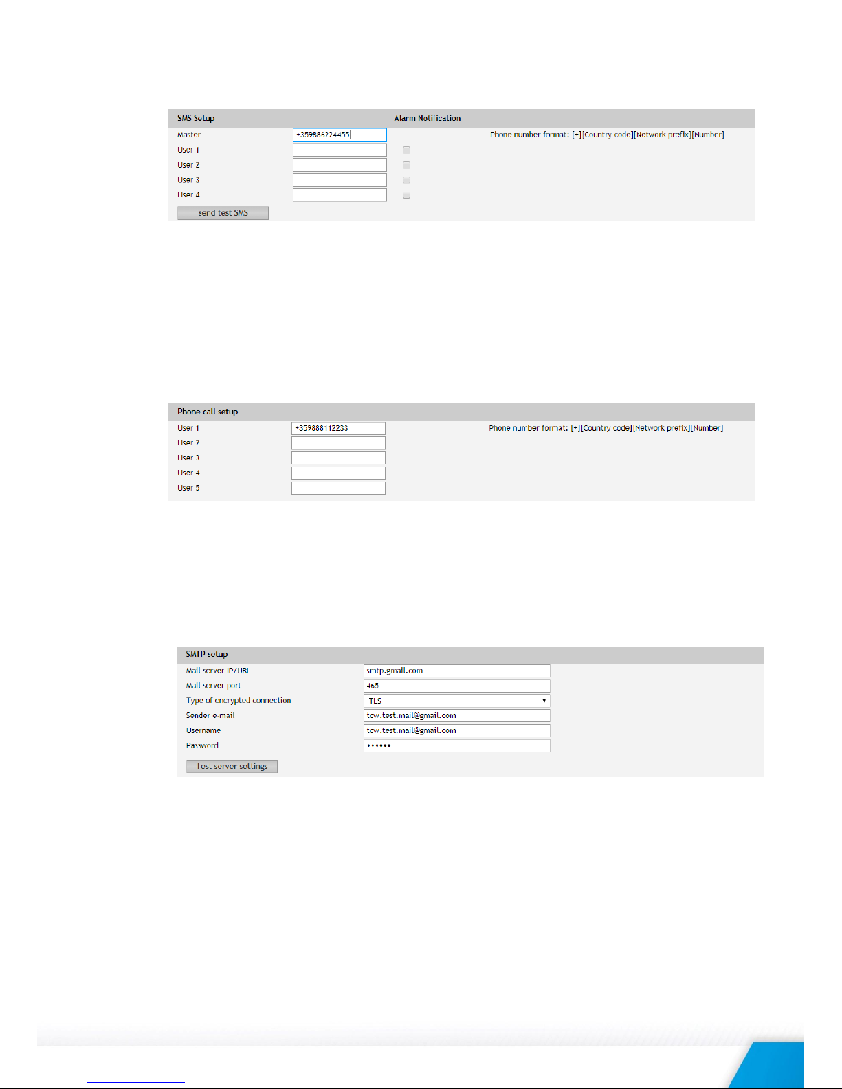
7.2.1. SMS/Call
SMS alarm recipients can be set in this section.
The “Master” has special rights to change the device settings using SMS commands. This number
always receive the SMS alarm messages.
The remaining 4 recipients can receive SMS messages if any of the parameters is in an alarm
state. To receive the SMS messages for every number should be enabled with the checkbox
“Alarm Notification”. These 4 recipients can also ask by SMS for parameter state/value.
By pressing “send test SMS” button all SMS recipients will receive a test SMS.
All commands, their syntax, and answers are described in “Setup via SMS”.
The relay outputs can be activated (pulse only) by a single call from an authorized number. The
maximum number of the authorized numbers is five. These numbers can be set through the WEB
interface or by sending an SMS from the Master.
7.2.2. SMTP
This page is used to enter valid SMTP settings for email alerts and recipients’ addresses.
7.2.2.1. SMTP setup
Mail server address can be set either by hostname (smtp.gmail.com) or IP address.
The e-mails can be sent with or without an encrypted connection.
The default SMTP port without encryption is 25. Almost all ISP’s block this port to avoid
hacker’s attacks. Ask your ISP for details.
The only supported method for encrypted connection from most of the public email servers is
TLS. TCG140 supports TLS 1.0, TLS 1.1 and TLS 1.2 with RSA_WITH_AES_128_GCM_SHA256
and RSA_WITH_AES_128_CBC_SHA cipher suites. This ensures successful operation with
almost all public servers.
Be careful with the terms SSL, TLS, and STARTTLS used in email server settings, supplied by the
provider. Some providers as Gmail uses SSL instead of TLS and TLS instead of STARTTLS. This
 Loading...