

Teracom TCG120 User Manual


TCG120 _R1.1 - March 2015
Page 2
GSM/GPRS controller TCG120
1. Introduction
TCG120 is a micro-controller based device for monitoring and control via the GSM network. The
controller has 2 digital inputs, 2 analog inputs, 1-Wire interface for up to 4 Teracom humidity and
temperature sensors. It also has 2 relays with normally open and normally close contacts.
The relays can be activated either remotely (via SMS or HTTP API command) or locally - from
status of monitored parameter. Only one parameter can manage the relay at the same time, but for
every parameter can be sent e-mail or SMS for alert conditions.
TCG120 may periodically send data to a remote server, which makes it suitable for use in clientserver monitoring and control systems.
2. Features
Quad-bands connectivity;
Setup via USB (Windows setup program) or SMS;
2 digital inputs with " dry contact" and "logic level" modes;
2 analog inputs with 0 to 60VDC range;
2 relays with NO and NC contacts;
Long 1-Wire support for up to 4 Teracom TSTxxx (temperature) and TSHxxx
(temperature&humidity) sensors;
SMS alarm alerts (up to 5 numbers)
Email alarm alerts (up to 5 email recipients), SMTP with SSL support;
Single call control – the relays can be controlled with a single call from up to 100 numbers;
Push mode – XML data is sent via HTTP post method to remote server;
HTTP API commands;
Firmware update over USB or GPRS.
3. Applications
Remote control – the relay outputs can be controlled with SMS, HTTP command or by a single
call from authorized number.
Temperature&Humidity control – TCG120 supports Teracom TSTxxx (temperature) and TSHxxx
(temperature&humidity) 1-wire sensors. The relay outputs can be controlled from the value of
the measured parameters. The minimum, maximum and hysteresis values can be set during the
initial setup (via USB) or by SMS.
Status reporter – SMS and E-mail alerts can be sent to the authorized recipients. The alerts can
be triggered if some of the measured parameters (temperature, humidity, analog inputs, digital
inputs) is in alarm state.
SCADA systems – TCG120 controller is designed for easy SCADA systems integration. Using
PUSH function makes it possible to build systems where many controllers from different places
are sending data to a remote server.

TCG120 _R1.1 - March 2015
Page 3
4. Technical parameters
Supply voltage, VDC
8 - 32
Maximum current consumption (with both relays ON), mA
140@12VDC
Weight, g
130
Dimensions, mm
107 x 72 x 32
Operating temperature, °C
0 to +40
Maximum humidity in 0 to 31°C range, %RH
80
Maximum humidity at 40°C (linear slope between 31-40°C), %RH
50 Quad band connectivity, MHz
850/900/1800/1900
GPRS Multi-slot Class
12, 1~12 configurable
GPRS Mobile Station
Class B
Compliant to GSM Phase 2/2+
Class 4
(2W@850/ 900MHz)
Class 1
(1W@1800/1900MHz)
Minimum high level input voltage for digital inputs, VDC
+2.5
Maximum low level input voltage for digital inputs, VDC
+0.8
Maximum input voltage for digital inputs, VDC
+5.5
Supply voltage for 1-wire bus (VDD), VDC
5.0 ± 0.2
Maximum output current for 1-wire bus (VDD), A
0.2
Analog inputs range, VDC
0 to +60
Maximum switchable current for relay contacts, А
3
Maximum switchable voltage for relay contacts, VAC/VDC
30/24
5. LED indicators
The following indicators show the status of the controller:
REL1-REL2 (green) – these LEDs are illuminated whenever the corresponding relay is
activated (the NO contact is closed and the NC contact is open);
SIG (red) – this LED is used to indicate the GSM network signal level;
STA (yellow) – indicates the working state of TCG120 controller and system messages.
The controller states and system messages are shown in Appendix A.
TCG120 _R1.1 - March 2015
Page 4
6. Installation
This device must be installed by qualified personnel. Installation consists of mounting the device,
connecting to the GSM network, connecting inputs and outputs, providing power and configuring via a
web browser. This device must not be installed directly outdoors.
Attention! Before installing the SIM card in the card slot, please ensure that the PIN code is
disabled.
6.1. Mounting
TCG120 should be mounted in a clean and dry location on not flammable surface. Ventilation is
recommended for installations where ambient air temperature is expected to be high.
Mount the device to a wall by using two plastic dowels 8x60mm (example Würth GmbH 0912
802 002) and two dowel screws 6x70mm (example Würth GmbH 0157 06 70). Attach the screws to the
surface vertically. See Appendix-A, fig. 1 for mechanical details.
Maintain spacing from adjacent equipment. Allow 50 mm of space on all sides, as shown on fig.2 in
Appendix A, this provides ventilation and electrical isolation.
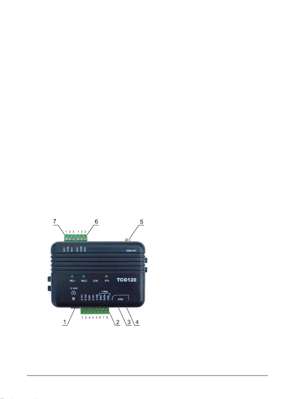
6.2. Connectors
Attention! Disconnect power supply before wiring.
The correct wiring procedure is as follows:
Make sure power is turned off;
Make wiring connections to the terminals;
Apply power.
It is recommended to test and configure TCG120 without any controlled device
Make sure that wires are properly attached to the terminals and that the terminals are tighten. Not
proper wiring and configuration can cause permanent damage of TCG120 or the equipment to which it
is connected or both. Inputs and outputs locations are shown below:
Connector 1 – Power - central positive
Connector 2, Pin1 - Digital input 1 (Din1)*
Connector 2, Pin2 - Digital input 2 (Din2)*
Connector 2, Pin3 - Ground
Connector 2, Pin4 - Analog input 1 (Ain1)
Connector 2, Pin5 - Analog input 2 (Ain2)
Connector 2, Pin6 - Ground
Connector 2, Pin7 – 1-Wire data
Connector 2, Pin8 – 1-Wire power supply
Connector 3 – mini USB
Connector 4 – SIM card holder
Connector 5 – GSM Antenna
Connector 6, Pin1 – NC Relay1
Connector 6, Pin2 – COM Relay1
Connector 6, Pin3 – NO Relay1
Connector 7, Pin1 – NC Relay2
Connector 7, Pin1 – COM Relay2
Connector 7, Pin1 – NO Relay2
* Operating mode is selected by jumper DI1/DI2 - closed for “dry contact” and open for “logic
level”. By default jumpers are closed.

TCG120 _R1.1 - March 2015
Page 5
6.2.1. Power supply connection
TCG120 is designed to be supplied by adapter SYS1421-0612-W2E or similar, intended for use in the
conditions of overvoltage category II. The power supply equipment shall be resistant to short circuit and
overload in secondary circuit.
When in use, do not position the equipment so that it is difficult to disconnect the device from the
power supply.
6.2.2. Digital inputs connection
Attention! Digital inputs are NOT galvanic isolated.
The TCG120 digital inputs can be used in two modes – “dry contact” and “logic level”. The mode is
determined by the jumper, close to the corresponding input. To change the operation mode, the plastic
enclosure must be opened. Closed jumper determines “dry contact” mode while open “logic level”. By
default digital inputs are in “dry contact” mode.
In “dry contact” mode digital inputs can be used to monitor the state of a discrete device – door
contact switch, push button, PIR detector etc.
Following picture illustrates how a dry contact switch can be connected to the input (or inputs) of
TCG120. One side of the contact is connected to “Digital In” and the other side is connected to “GND”
terminals.
6.2.3. Analog inputs connection
Attention! Analog inputs are NOT galvanic isolated.
Analog inputs of TCG120 can be used for monitoring of DC voltage up to 60VDC. They can be
connected directly to batteries, solar panels, power supplies etc.
Built in functionality “Multiplier”, “Offset” and “Dimension” for every analog input gives possibility
to monitor sensors with analog outputs and see directly measured parameter. It is also possible to
monitor voltages bigger than 60 VDC with external resistive dividers.
Following picture illustrates how a battery can be connected to the analog input of TCG120. One
side of the contact is connected to “Analog In” and the other side is connected to “GND” terminals.

TCG120 _R1.1 - March 2015
Page 6
6.2.4. Sensor connection
Up to 4 1-Wire sensors can be connected to TCG120 controller. The device supports TSTxxx
(temperature) and TSHxxx (humidity&temperature) sensors.
1-Wire is a registered trademark of Maxim Integrated Products, Inc. It is designed to connect
several sensors over a short wiring. It is not suitable for long distances or environments with EMC
interference. We recommend reading Maxim’s 1-Wire tips at http://www.maxim-ic.com/appnotes/index.mvp/id/148.
The sensors have three wires – positive voltage (+VDD), ground (GND) and bidirectional data (Data).
The colors of wires for every sensor are specified in its user manual.
It is strongly recommended to use “daisy chained” (linear topology) for multiple sensors:

TCG120 _R1.1 - March 2015
Page 7
“Star” topology can be used only as a last resort for up to 4 sensors and total cable length up to 10
meters:
There are many parameters which determine the maximum length of the wires - type of cable, the
number of sensors, ambient electromagnetic noise and sensor network topology.
It is strongly recommended to use only UTP/FTP cables and keep total cable length up to 60 m.
Although functionality has been achieved in longer distance, we cannot guarantee error-free operation
over mentioned wiring length.
We guarantee proper operation only with Teracom 1-Wire sensors.
6.2.5. Relay connection
The relay contacts are internally connected directly to the terminal connectors. For all relays
normally open, normally close and common contacts are available. For loads with higher switchable
current/voltage than specified, an external relay should be used.
When mechanical relays switch inductive loads such as motors, transformers, relays, etc., the
current will arc across the relay contacts each time the contacts open. Over time, this cause wears on
the relay contacts which shorten their life. When switching an inductive load, it is recommended that
relay contact protection devices are used.
TCG120 _R1.1 - March 2015
Page 8
7. Initial setup via USB
The initial setup of TCG120 controller is done with a computer running Windows 7 or newer
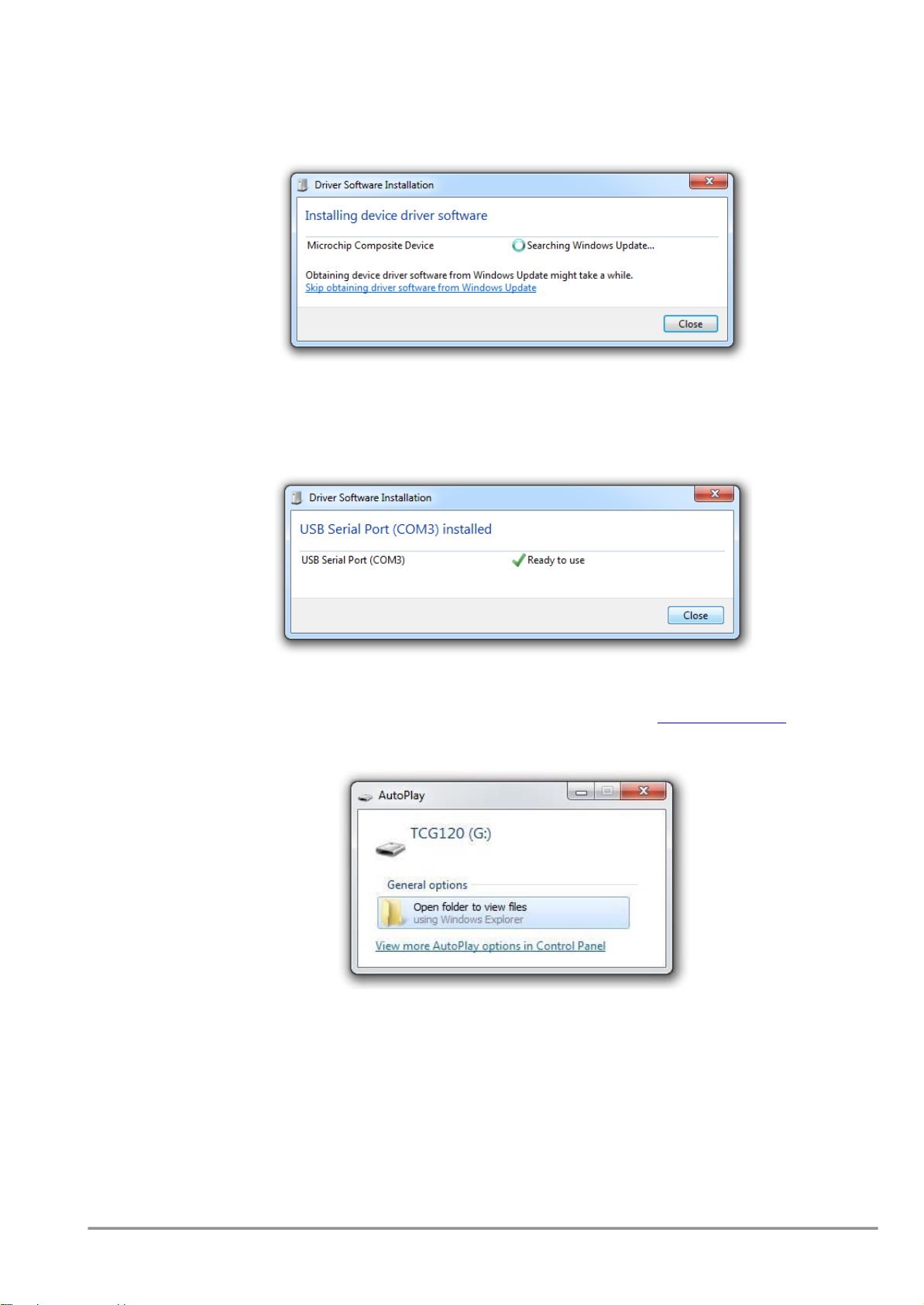
Microsoft Windows operating system. After power-up, the controller should be connected to the
computer with USB cable. Once the USB cable is connected, the operating system automatically starts to
install the drivers for the communication with the device. The following message appears:
The following drivers will be installed:
- Microchip composite device
- USB serial port driver
If for some reason the USB serial port driver cannot be installed automatically, it must be installed
manually. The driver can be downloaded from the TCG120 product page at www.teracom.cc . After
successful driver installation the device will be recognized as Mass storage, the following window
appears on the screen:
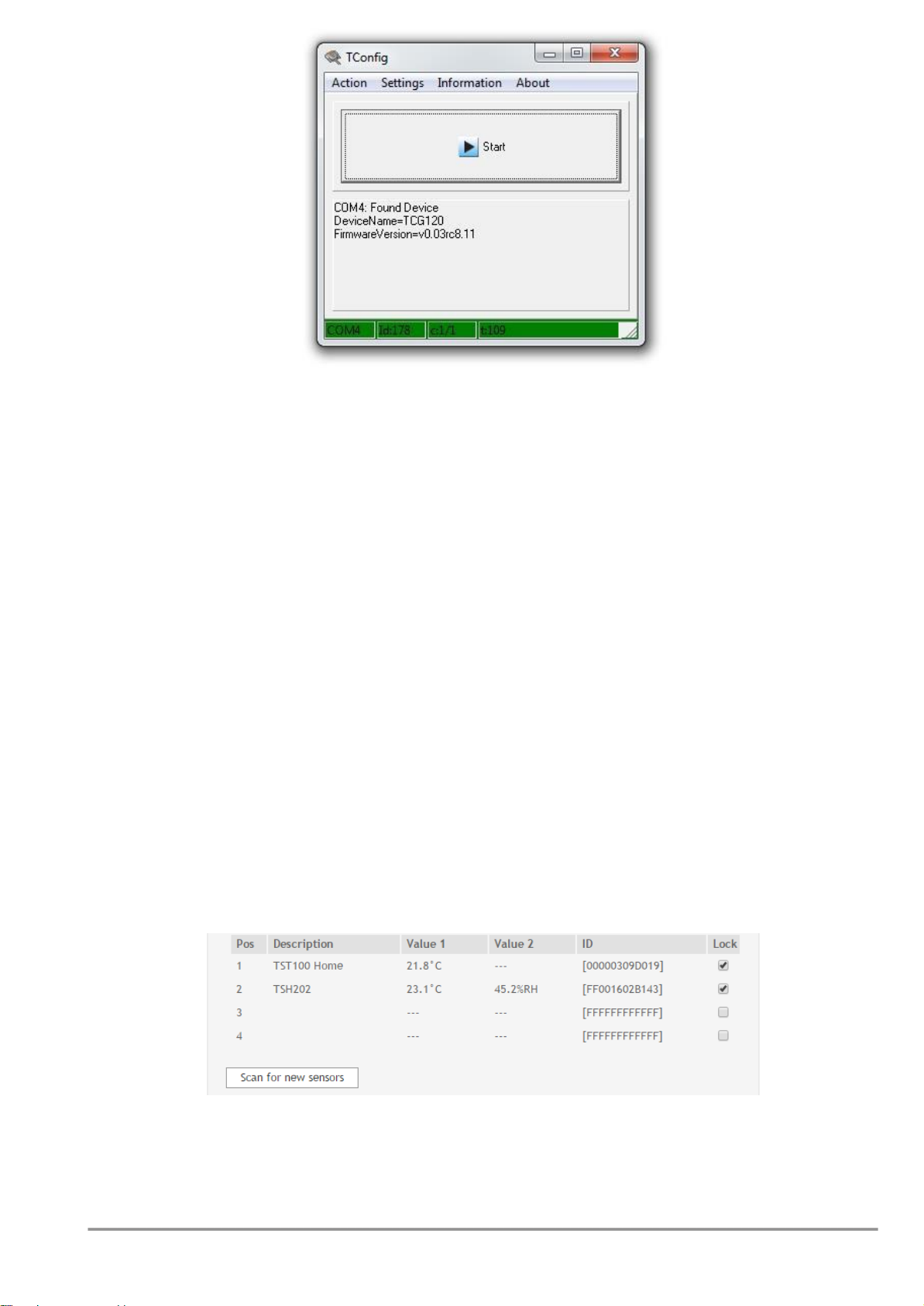
The only file stored on the mass storage is a tool called “TConfig”. This tool enables the
communication between the TCG120 and PC. After starting the TConfig tool, the following program will
appear:
TCG120 _R1.1 - March 2015
Page 9
Pressing the “Start” button will start your web browser and display the Monitoring page of your
TCG120 controller.
7.1. Monitoring page
Monitoring page displays the current I/O state of TCG120 controller. The page has 4 sections –
“Sensors”, “Digital inputs”, “Analog inputs” and “Relays”.
For every parameter (sensor, input, relay) there is a description of up to 20 characters. The default
descriptions can be changed in “Setup-Input/Output” menu.
The Monitoring page can be automatically refreshed on an interval of 0 to 254 seconds. Zero means
no automatic refresh. This parameter is set in section “Setup->System->Monitoring page automatic
refresh”. By default it is 30 seconds.
7.1.1. Sensors section
All detected 1-Wire sensors are shown in this section. Sensor detection is made either after
connecting the power supply or by “Scan for new sensors” button. All found sensors are shown in
ascending order refer their unique ID number. For every sensor there are description, value, and ID
information.
Teracom temperature sensors readings are shown in the Value 1 column. TSH2xx
temperature/humidity sensors have the 2nd parameter shown on the Value 2 column.
It is possible to lock sensors in a specific position. To do this all sensors should be added one by one.
After every addition new scan should be made and newly found sensor should be locked in its position.
If all sensors are locked, removing one “in the middle” will not change the positions of following sensors
after reset. This option is very useful when TCG120 is used like a part of monitoring and control system
managed either by SNMP or HTTP API commands.
7.1.2. Digital inputs section
Digital inputs can be used for monitoring the state of discrete devices – motion sensor, door
contact, relay contact, alarm output etc. Both digital inputs are not galvanic isolated.
 Loading...