

Teracom T2-B-Gawv1 4U10Y-BI User Manual

Contents
1 Introduction ........................................................................................................1
1.1 Packing List...........................................................................................1
1.2 Safety Cautions .....................................................................................1
1.3 LEDs and Interfaces..............................................................................2
2 Hardware Installation .........................................................................................5
3 Web Configuration Management .......................................................................7
3.1 Preparation before Login.......................................................................7
3.1.1 Setup ..........................................................................................7
3.1.2 Setting up WAN and LAN connections.......................................7
3.1.3 PC Network Configuration..........................................................7
3.1.4 Connection between the Modem and PC...................................9
3.2 Login in to the Modem.........................................................................10
3.3 Home................................................................................................... 11
3.3.1 Overview................................................................................... 11
3.3.2 System Log...............................................................................15
3.3.3 Troubleshooting........................................................................16
3.4 Configuration .......................................................................................17
3.4.1 Wireless Network......................................................................17
3.4.2 Internet Connection ..................................................................23
3.4.3 Local Network (LAN).................................................................62
3.4.4 Voice Configuration................................................................... 66
3.4.5 DHCP Server............................................................................75
3.4.6 DHCP Relay .............................................................................81
3.4.7 IPv6 Prefix ................................................................................82
3.5 Security................................................................................................83
3.5.1 IP Filtering.................................................................................83
3.5.2 Port Forwarding........................................................................85
3.5.3 Virtual Server............................................................................86
3.6 Services...............................................................................................87
3.6.1 IGMP Proxy ..............................................................................87
3.6.2 IPv4 Routing.............................................................................88
3.6.3 IPv6 Routing.............................................................................90
3.6.4 Quality of Service......................................................................91
3.6.5 Mac Filtering.............................................................................94
i

User Manual for T2-B-Gawv1.4U10Y.BI
3.7
DSL Home...........................................................................................98
3.7.1 Management Server.................................................................98
3.7.2 CWM Parameters...................................................................101
3.8 Port Statistics.....................................................................................101
3.8.1 Voipfxs0..................................................................................101
3.8.2 Voipcmdstat............................................................................104
3.8.3 DSL.........................................................................................106
3.8.4 Ethernet0/1/2/3.......................................................................109
3.8.5 Wireless...................................................................................111
3.9 Admin ................................................................................................ 113
3.9.1 Firmware Upgrade..................................................................113
3.9.2 Back & Restore....................................................................... 114
3.9.3 Reboot.................................................................................... 115
3.9.4 Remote Access....................................................................... 115
3.9.5 Lan Access .............................................................................116
3.9.6 Change Password ..................................................................117
3.9.7 Time Zone............................................................................... 117
4 Network Topology...........................................................................................120
4.1 PPP over ATM (PPPoA) Mode..........................................................120
4.2 PPP over Ethernet (PPPoE) Mode....................................................121
4.3 RFC2684 (Bridged) + Fixedly-Assigned IP Address Mode ...............123
4.4 RFC2684 (Bridged) + DHCP Mode...................................................124
4.5 RFC2684 (Routed) + NAT Mode.......................................................125
4.6 External PPPoE Dial-up Mode ..........................................................126
Teracom Limited ii An ISO Certificed Company

1 Introduction
The T2-B-Gawv1.4U10Y.BI is an ADSL2+ access device that supports multiple line
modes. It supports ADSL2/ADSL2+ and is backward compatible to ADSL. It also
offers auto-negotiation capability for different standards (e.g., G.dmt, T1.413 Issue
2) according to the settings of digital subscriber line access multiplexer (DSLAM) in
the central office. It provides four 10/100Base-T Ethernet interfaces and one USB
interface at the user end. By utilizing the high-speed ADSL connection, the
T2-B-Gawv1.4U10Y.BI can provide broadband connectivity to the Internet,
downstream up to 24 Mbps and upstream up to 1 Mbps.
The device supports WLAN access, such as WLAN AP or WLAN device, to the
Internet. It complies with IEEE 802.11, 802.11b/g specifications, WEP, WPA, and
WPA2 security specifications.
1.1 Packing List
1 x T2-B-Gawv1.4U10Y.BI
1 x External Splitter
1 x Power Adapter
2 x Telephone Cables (RJ-11)
1 x Ethernet Cables (RJ-45)
1 x Quick Start Guide
1 x Driver and Utility Software CD (With Motive Client Software)
1.2 Safety Cautions
Follow the following instructions to prevent the device from risks and damage
caused by fire or electric power:
Use volume labels to mark the type of power.
Use the power adapter packed within the device package.
Pay attention to the power load of the outlet or prolonged lines. An
overburden power outlet or damaged lines and plugs may cause electric
shock or fire accident. Check the power cords regularly. If you find any
damage, replace it at once.
Proper space left for heat dissipation is necessary to avoid damage caused
by overheating to the device. The long and thin holes on the device are
1
User Manual for T2-B-Gawv1.4U10Y.BI
designed for heat dissipation to ensure that the device works normally. Do
not cover these heat dissipation holes.
Do not put this device close to a place where a heat source exits or high
temperature occurs. Avoid the device from direct sunshine.
Do not put this device close to a place where it is over damp or watery. Do
not spill any fluid on this device.
Do not connect this device to any PCs or electronic products, unless our
customer engineer or your broadband provider instructs you to do this,
because any wrong connection may cause power or fire risk.
Do not place this device on an unstable surface or support.
1.3 LEDs and Interfaces
Front panel
The following table describes the LEDs of the device.
LEDs Color Status Description
Green
Power
Red
DSL Green
Green
Internet
Red On
Teracom Limited 2 An ISO Certificed Company
On The device is powered on.
Off The device is powered off.
On The device is initializing.
Blinks The firmware is upgrading.
On
Blinks The device is detecting itself.
Off The initial self-test is failed.
On
Blinks
Off
The initial self-test of the unit is normal
and ready.
The device has successful Internet
connection.
Data is being transmitted on the
Internet.
The Internet connection is failed or
DSL has no synchronization.
The device is dialing up before
obtaining IP address successfully by
PPP.
User Manual for T2-B-Gawv1.4U10Y.BI
LEDs Color Status Description
The device has successful Ethernet
connections.
Data is being transmitted through the
LAN interface.
The LAN connection is not
established.
The connection of WLAN interface is
normal.
Data is being transmitted through the
WLAN interface.
The WPS is active, waiting for the
remote client to establish connection.
Data is being transmitted through the
USB interface.
LAN4/3/2/1 Green
WLAN Green
WPS
VoIP1 Green
USB_H1 Green
Green
On
Blinks
Off
On
Blinks
Off No WLAN connection.
On The WPS is active.
Blinks
Off The WPS is inactive.
On The VoIP phone is registered.
Blinks The phone is off-hook.
Off The VoIP phone is not registered.
On The USB connection is normal.
Blinks
Off The USB connection is failed.
Rear panel
The following table describes the interfaces of the device.
Interface Description
Power
Teracom Limited 3 An ISO Certificed Company
Power switch, power on or power off the device.
Power interface, for connecting to the power adapter of 12 V
DC, 1 A.

User Manual for T2-B-Gawv1.4U10Y.BI
Interface Description
WLAN
Reset
WPS
USB
LAN1/2/3/4
Internet
FXS
WLAN switch, switch on or switch off the WLAN function.
Reset to the factory defaults. Keep the device powered on
and push a paper clip into the hole for over 3 seconds, then
release it. The configuration is restored to the factory
defaults.
WPS switch, switch on or switch off the WPS function.
USB Host Port, for connecting the device those have USB
Device Port (Like Pen Drive).
RJ-45 interfaces, for connecting to the Ethernet interface of
PC or Ethernet devices through the Ethernet cable.
RJ-11 interface for connecting to the telephone set through
the telephone cable.
Connect to phones for VoIP application.
Teracom Limited 4 An ISO Certificed Company
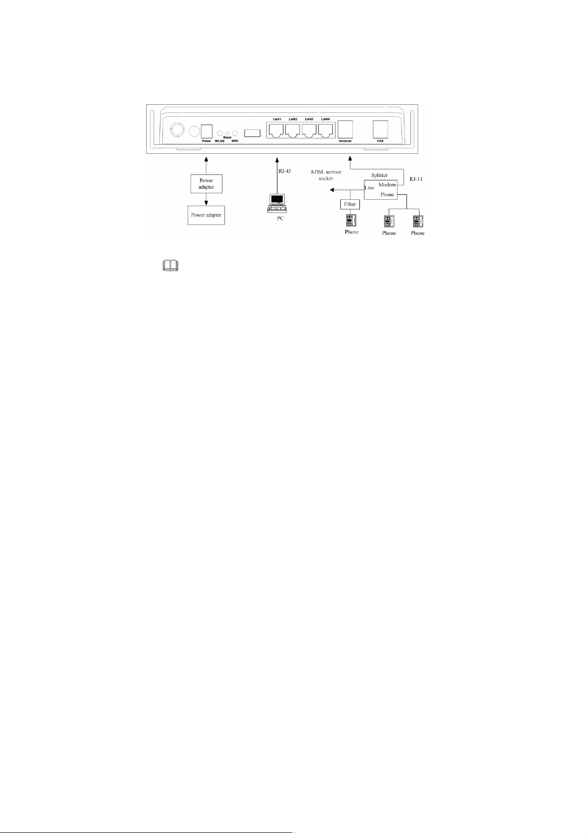
2 Hardware Installation
Step 1 Connect the Internet interface of the device and the Modem interface of
the splitter through a telephone cable. Connect the phone to the Phone
interface of the splitter through a telephone cable. Connect the incoming
line to the Line interface of the splitter.
The splitter has three interfaces:
Line: Connect to a wall phone interface (RJ-11 jack).
Modem: Connect to the DSL interface of the device.
Phone: Connect to a telephone set.
Step 2 Connect the LAN interface of the device to the network card of the PC
through an Ethernet cable (MDI/MDIX).
Note:
Use twisted-pair cables to connect with the Hub or Switch.
Step 3 Plug one end of the power adapter to the wall outlet and connect the
other end to the Power interface of the device.
Connection 1
The following connection method is recommended.
Figure 1 displays the application diagram for the connection of the router, PC,
splitter and the telephone sets, and no telephone set is placed before the splitter.
5
User Manual for T2-B-Gawv1.4U10Y.BI
Figure 1 Connection 1 (No phone is installed before a splitter)
Connection 2
Figure 2 displays the application diagram for the connection of the router, PC,
splitter and the telephone sets, and a telephone set is placed before the splitter.
Figure 2 Connection 2 (A phone is installed closed to the splitter)
Note:
When connection 2 is used, the filter must be installed close to the telephone
cable. See Figure 2. Do not use the splitter to replace the filter.
Installing a telephone directly before the splitter may lead to failure of connection
between the device and the central office, or failure of Internet access, or slow
connection speed. If you really need to add a telephone set before the splitter, you
must add a microfilter before a telephone set. Do not connect several telephones
before the splitter or connect several telephones with the microfilter.
Teracom Limited 6 An ISO Certificed Company

User Manual for T2-B-Gawv1.4U10Y.BI
3 Web Configuration Management
3.1 Preparation before Login
Before accessing the modem, ensure the communication between PC and the
modem is normal.
3.1.1 Setup
Connecting your PC or home network with the modem is a simple procedure,
varying slightly depending on the operating system (OS). This chapter helps you to
seamlessly integrate modem with your PC or home network. In most cases, the
setup procedure described below is unnecessary. For example, the default DHCP
setting in Windows 2000 is client, requiring no further modification. However, it is
advised to follow the setup procedure described below to verify that the
communication parameters and the physical cable connections are valid or correct.
3.1.2 Setting up WAN and LAN connections
WAN Connection
Your PC can connect to the Internet by ADSL. Connect its Internet socket to the
wall socket through a telephone cable. If it has an Ethernet socket for the wide area
network (WAN), connect it to the external ADSL or to the Ethernet socket through
an Ethernet cable.
LAN Connection
Your PC can connect to the gateway with the LAN interface. Use an Ethernet cable
to establish the connection between an LAN interface of your modem and the
network card of your PC.
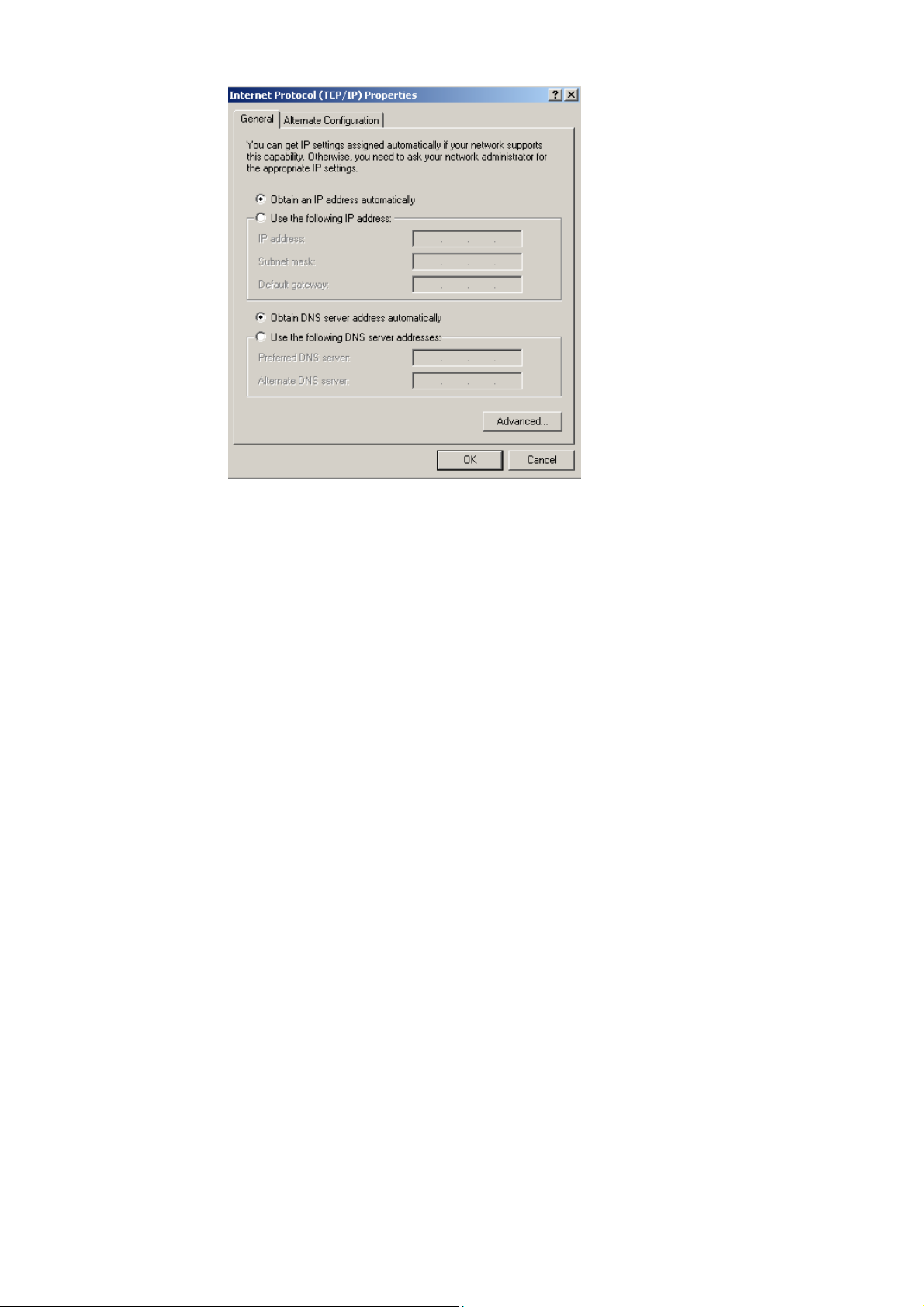
3.1.3 PC Network Configuration
Each network interface on the PC should either be configured with a statically
defined IP address and a DNS address, or should be instructed to automatically
obtain an IP address from the network DHCP server . The modem provides a DHCP
server on the LAN side and it is recommended to configure your LAN to obtain its
IP address and the IP address of the DNS server automatically.
This configuration principle is identical but operations are differently on each OS.
Teracom Limited 7 An ISO Certificed Company
User Manual for T2-B-Gawv1.4U10Y.BI
Figure 3 displays the TCP/IP Properties dialog box in the Windows XP system.
Figure 3
Windows XP
(1) Open the Control Panel and click Network Connections.
(2) Right-click the Ethernet connection icon and choose Properties from the
shortcut menu.
(3) On the General tab, select the Internet Protocol (TCP/IP) component, and
click Properties. The Internet Protocol (TCP/IP) Properties window appears.
(4) Select Obtain an IP address automatically.
(5) Select Obtain DNS server address automatically.
(6) Click OK to save the settings.
Windows 2000/98/Me
(1) Open the Control Panel and click Network and Dialing Connections.
(2) Right-click the Ethernet connection icon and choose Properties from the
shortcut menu. The Connection Properties window appears.
Teracom Limited 8 An ISO Certificed Company
User Manual for T2-B-Gawv1.4U10Y.BI
(3) Select the Internet Protocol (TCP/IP) component and click Properties.
(4) The Internet Protocol (TCP/IP) Properties window appears.
(5) Select Obtain an IP address automatically.
(6) Select Obtain DNS server address automatically.
(7) Click OK to save the settings.
Windows NT
(1) Open the Control Panel and click Network.
(2) On the Protocol tab, select the Internet Protocol (TCP/IP) component, and
click Properties.
(3) On the IP Address tab, select the Obtain an IP address automatically option.
(4) On the DNS tab, ensure that no DNS server is defined in the DNS Service
Search Order box and that no suffix is defined in the Domain Suffix Search
Order box.
Linux
(1) Login in to the system as a super user, by entering su in the terminal window.
(2) Enter vi /etc/sysconfig/network-script/ifcfg-eth0 to modify the eth0 network
devices and assign IP addresses.
(3) Enter ifconfig to view the newly assigned IP addresses.
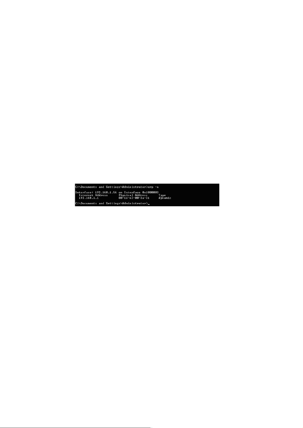
3.1.4 Connection between the Modem and PC
The procedure of checking the connection between the modem and PC is as follows:
(1) Configure the IP address of the PC as 192.168.1.X (2~254), netm ask as 255.
255.255.0, and gateway address as 192. 168.1.1 (for a customized version,
configure them according to the actual version).
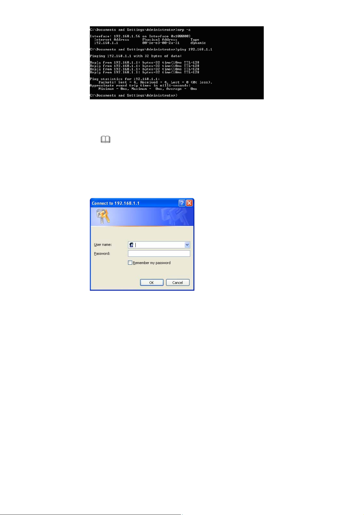
(2) Enter arp -a in the DOS window to check whether the PC can read the MAC
address of the DSL. See Figure 4.
Figure 4
(3) Ping the management IP address (by default, 192.168.1.1) of the modem.
Teracom Limited 9 An ISO Certificed Company
User Manual for T2-B-Gawv1.4U10Y.BI
If the PC can read the MAC address of the device and ping the management IP
address of the device successfully, the connection between the modem and PC is
normal.
Note:
When you manage the device through Web, you must keep the power of the
device on. Otherwise, the device may be damaged.
3.2 Login in to the Modem
(1) Open the Internet Explorer and enter http://192.168.1.1.
(2) Enter the user name and a p assword. See Figure 5. The default user name and
password are admin and admin respectively.
Teracom Limited 10 An ISO Certificed Company
User Manual for T2-B-Gawv1.4U10Y.BI
Figure 5
Click OK and the main interface appears.
After logging in to the modem as a super user, you can check, configure, and
modify all the settings. You can also diagnose the device system.
3.3 Home
Click Home to enter system information page. On the left page, there are three
options: Overview, System Log, and Troubleshooting.
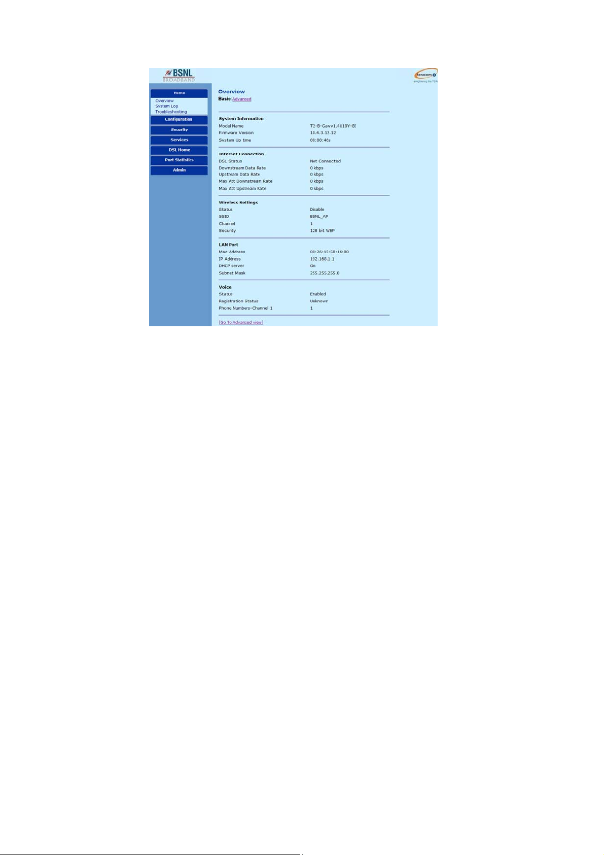
3.3.1 Overview
This page displays the current status and configuration of the system. It contains
the status of the modem. Such as, firmware version, system uptime, downstream
data rate, upstream data rate, DSL status, wirelss and voice status.
Teracom Limited 11 An ISO Certificed Company
User Manual for T2-B-Gawv1.4U10Y.BI
3.3.1.1 Basic
Choose Overview > Basic and the following page appears.
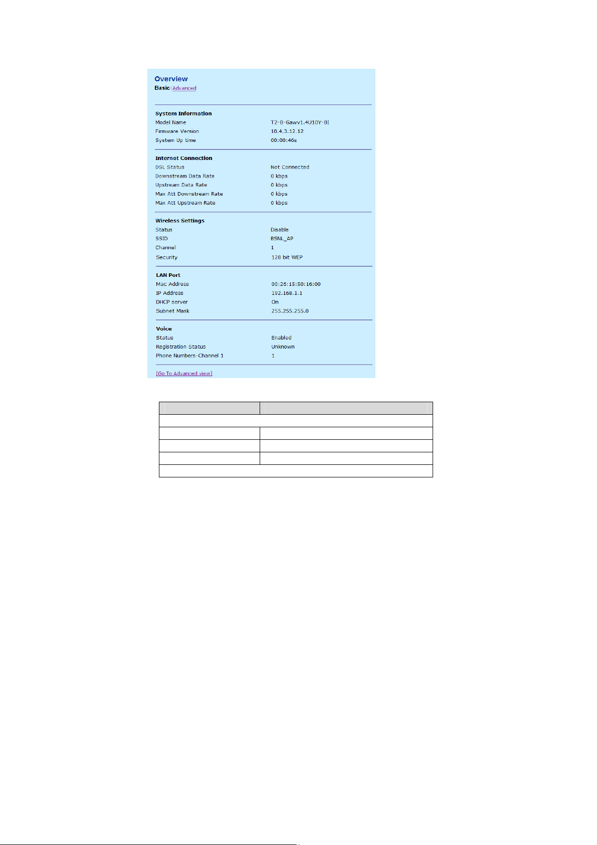
The following table describes the parameters of this page.
Field Description
System Information
Model Name It displays the model name of the modem.
Firmware Version The software version of the modem.
System Up time Uptime of the modem.
Internet Connection
Teracom Limited 12 An ISO Certificed Company

User Manual for T2-B-Gawv1.4U10Y.BI
Field Description
DSL Status The status of the ADSL port.
Downstream Data Rate Down line rate.
Upstream Data Rate Up line rate.
Wireless Settings
Status The status of the wireless network.
Service set identification (SSID) is a unique
SSID
LAN Port
Mac Address The MAC address of the modem.
IP Address The IP address of the modem.
DHCP server The current status of the DHCP server.
Voice
Status The VoIP status.
Registration Status
Note:
The firmware version displayed in this page may be inconsistent with the actual
software version, and is for reference only.
name to identify the modem in the wireless
LAN.
It displays the registration status of VoIP
application.
3.3.1.2 Advanced
Click Advanced in the Overview page and the following page appears.
Teracom Limited 13 An ISO Certificed Company
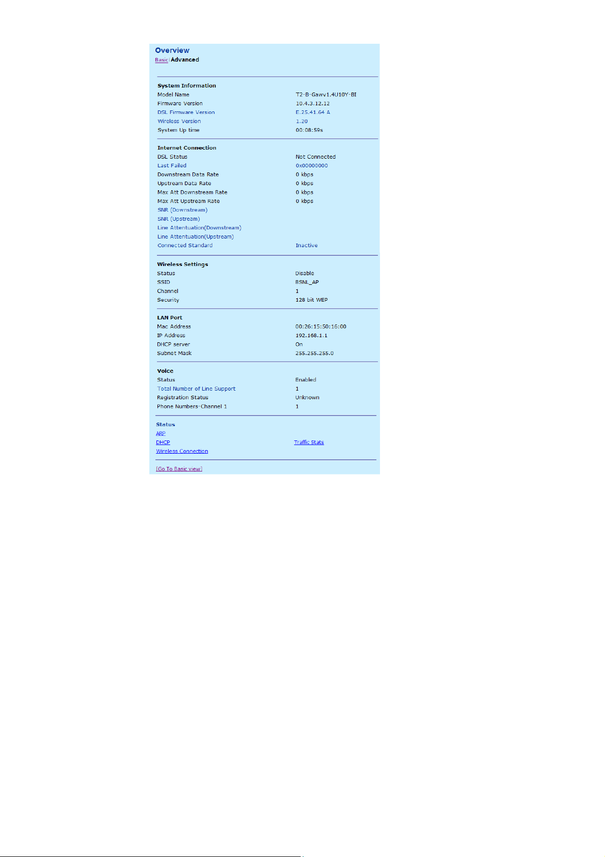
User Manual for T2-B-Gawv1.4U10Y.BI
Teracom Limited 14 An ISO Certificed Company
User Manual for T2-B-Gawv1.4U10Y.BI
The following table describes the parameters of this page.
Field Description
System Information
DSL Firmware Version The hardware version of the modem.
Wireless version The wireless version of the modem.
Internet Connection
Connected Standard The status of the line mode.
It contains the configuration information about
Status
Note:
The rate is measured under a zero -kilometer link. In the circumstances, the
gateway is automatically set, and the DNS addresses are obtained from the
BRAS.
ARP, DHCP Traffic Stats, and Wireless
Connection.
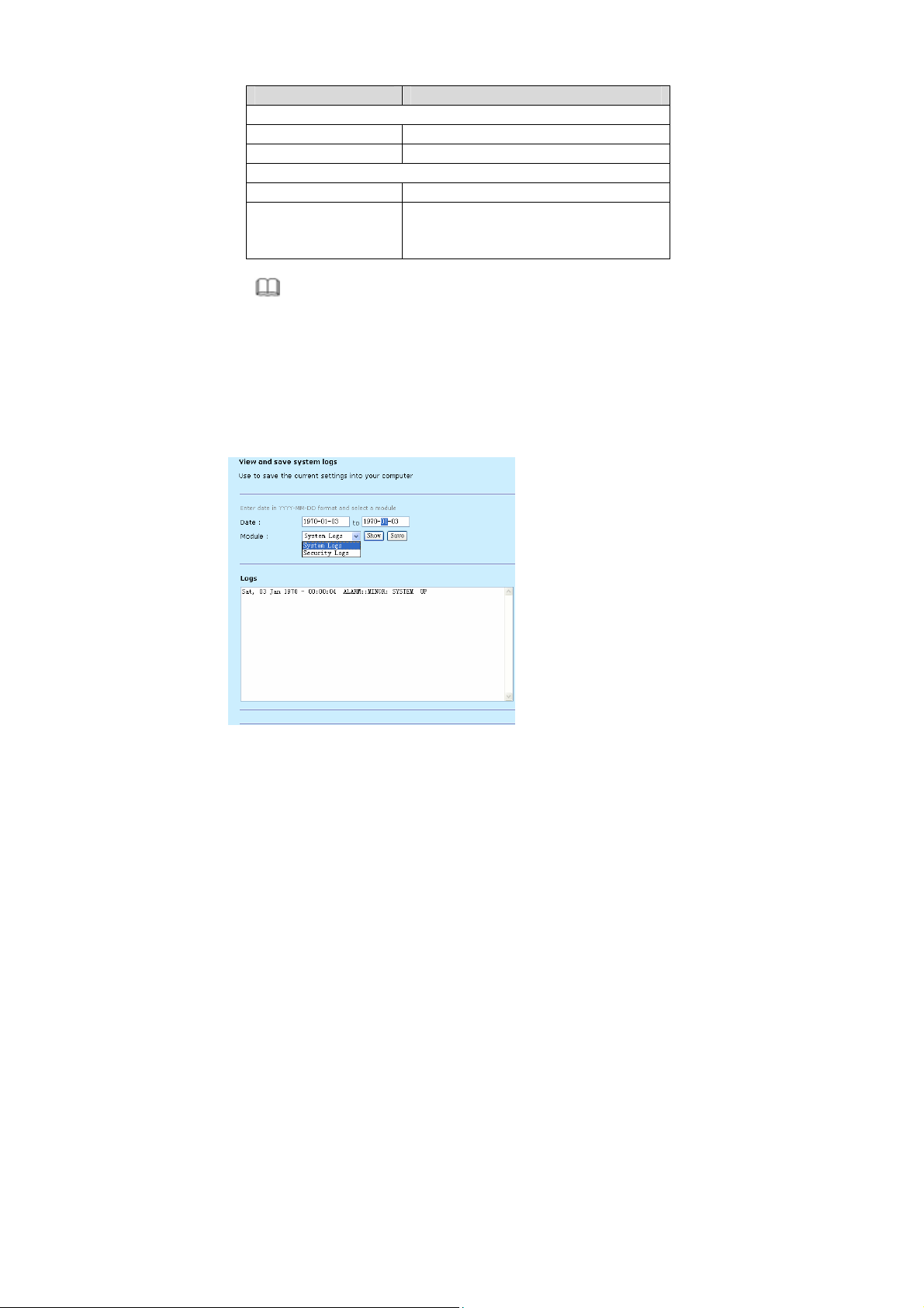
3.3.2 System Log
Choose Home > System Log and the following page appears. In this page, you
can consult the logs after relevant settings. You can also save the current settings
to your PC.
Teracom Limited 15 An ISO Certificed Company
User Manual for T2-B-Gawv1.4U10Y.BI
Note:
Set the query time consistent with the SNTP if you want to obtain the real-time
of the system logs.
3.3.3 Troubleshooting
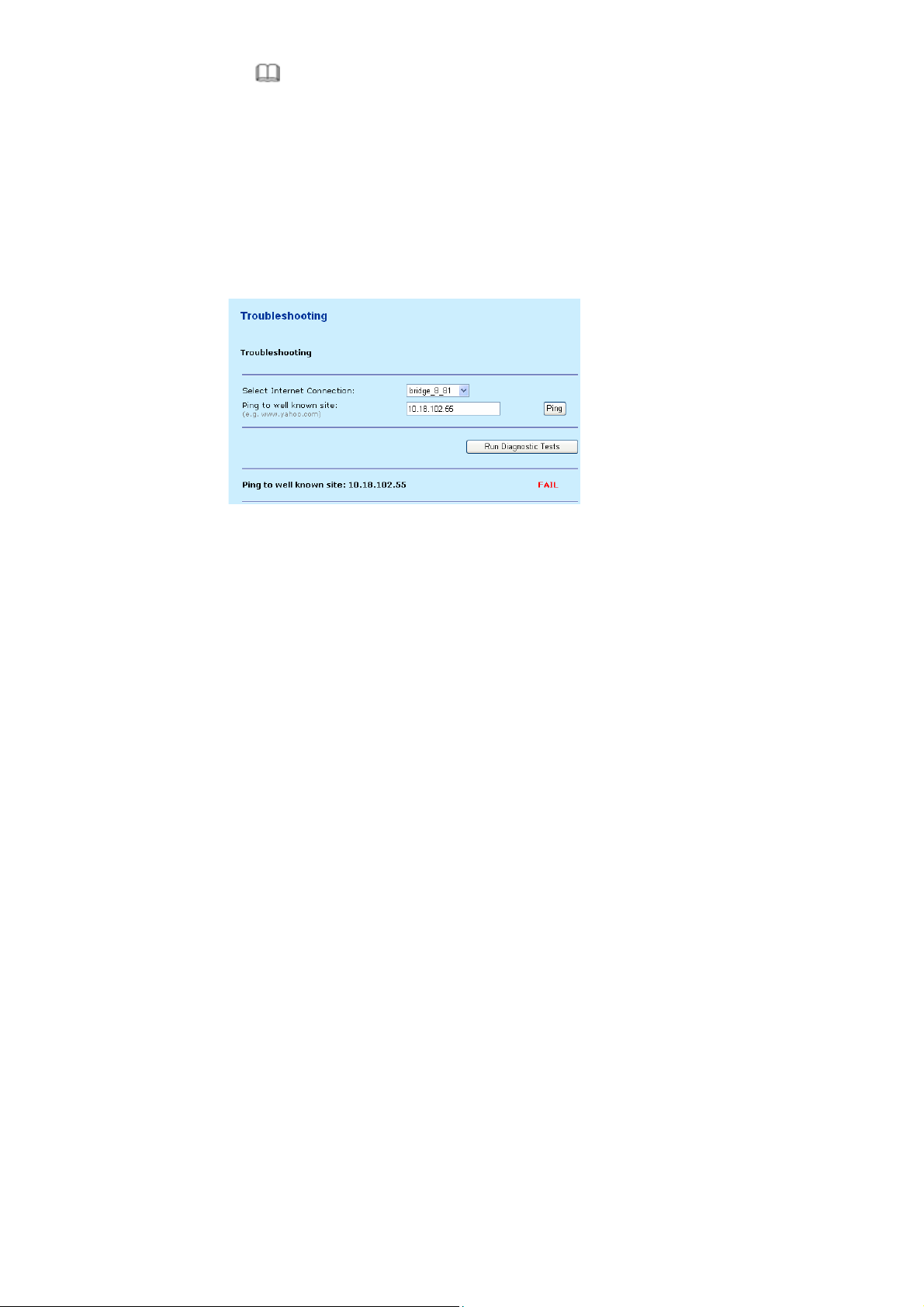
Choose Home > Troubleshooting to enter the troubleshooting page. This page is
used to carry out diagnostic test. Troubleshooting allows you to carry out diagnostic
tests on your local Ethernet and WAN connection by ping the web site or running
the diagnostic tests. The tests results can be used to identify all the problems that
are related to your DSL connection or the configuration of the modem.
Enter a well-known site ( for example, IP 10.18.102.55) that you want to test. Click
Ping and the following page appears.
If the network connects well and the IP address or the site is effective, the ping of
the well-known site passes. Otherwise, it is failed to ping the well-known site.
Select the Internet connection that you want to test from the drop-down list (take
bridge_8_81 for example). Click Run Diagnostic Tests and the following page
appears. In this page, you can view the test result.
Teracom Limited 16 An ISO Certificed Company

User Manual for T2-B-Gawv1.4U10Y.BI
The information that is displayed helps you to locate the problems.
3.4 Configuration
Click Configuration to enter system configuration page. On the left page, there are
seven options: Wireless Network, Internet Connection, Local Network (LAN),
Voice Configuration, DHCP Server, DHCP Relay, and IPv6 Prefix. You can
modify LAN and WAN settings, such as PVC, LAN port, and DHCP.
3.4.1 Wireless Network
A wireless local area network (WLAN) provides a flexible data communications
system that you can use to access various services, such as, surfing on the
Internet, E-mail, and printing services, without the cable connection. You can
connect to the Internet while roaming around in the converage area.
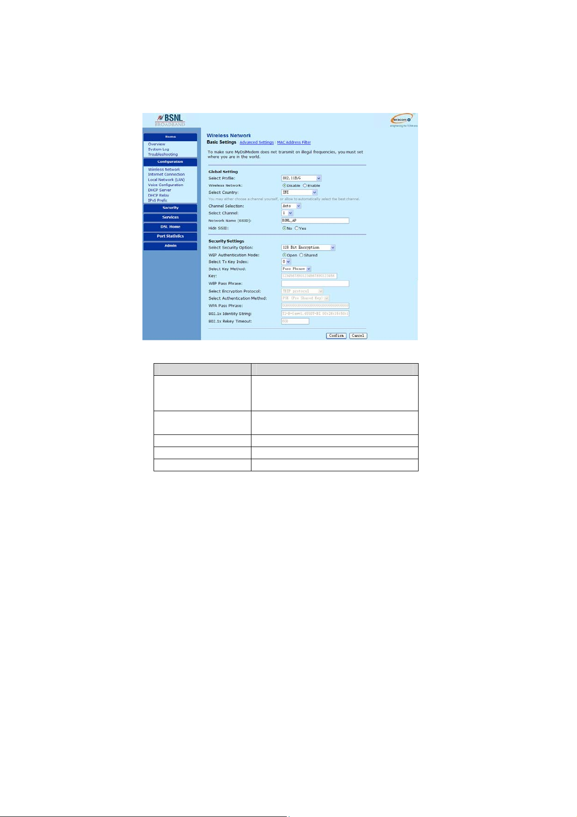
Choose Configuration > Wireless Network and the following page appears. In
this page, you can configure the parameters for wireless LAN clients that may
connect to the modem.
Teracom Limited 17 An ISO Certificed Company
User Manual for T2-B-Gawv1.4U10Y.BI
3.4.1.1 Basic Settings
By Default WiFI is disbaled in your CPE, and its using default SSID as “BSNL_AP”.
please configure the WiFI if you want to us it.
Choose Wireless Network > Basic Settings and the following page appears. You
must set the location where you are in order to prevent the modem from
transmitting the illegal frequencies.
The following table describes the parameters of this page.
Field Description
Choose the security specification. You can
Select Profile
Wireless Network
Select Country Choose the country where the modem works.
Channel Selection You can choose Auto or Manual.
Select Channel A channel is the radio frequency(ies) used by
Teracom Limited 18 An ISO Certificed Company
choose 802.11 B/G, 802.11B only, 802.11G
only, or 802.11 MIXED_LONG.
Enable or disable the wireless network. If you
want to connect to the Internet, enable it.

User Manual for T2-B-Gawv1.4U10Y.BI
Field Description
802.11b/g wireless device. Channels
available depend on your geographical area.
Service set identification (SSID) is a unique
name to identify the modem in the wireless
Network Name(SSID)
Hide SSID
Select Security Option
LAN. All wireless devices on a WLAN must
use the same SSID in order to communicate
with each other. By default, the SSID of the
modem is BSNL_AP.
You can enable or disable this SSID.
If you select Yes, the wireless adaptor
will fail to auto-search the SSID .The
auto-searching list does not display the
SSID. However, if you know the SSID,
you can set the connection manually.
If you select No, the auto-searching list
displays the SSID.
It is vital to protect wireless communication
between wireless stations, access points and
wired network. There are six options.
3.4.1.2 Advanced Settings
Click Advanced Settings in the Wireless Network page and the following page
appears. In this page, you can configure the parameters for wireless LAN clients
may connect to the modem. You can also modify the Fragmentation Threshold, Rts
Threshold, Nitroxm Piggyback and WMM.
Teracom Limited 19 An ISO Certificed Company
User Manual for T2-B-Gawv1.4U10Y.BI
The following table describes the parameters of this page.
Field Description
The fragmentation threshold is a way of
limiting the size of packets (frames)
Fragmentation Threshold
Teracom Limited 20 An ISO Certificed Company
transmitted over the network. If a packet
exceeds the configured fragmentation
threshold, the fragmentation function is

User Manual for T2-B-Gawv1.4U10Y.BI
Field Description
enabled, and the packets are sent as multiple
802.11 frames.
Request to send (RTS) is designed to prevent
collisions due to hidden node. A RTS defines
the biggest size data frame you can send
before a RTS handshake invoked. The RTS
RTS Threshold
NitroXM PiggyBack
threshold value is between 0 and 2347.
If the RTS threshold value is greater than the
fragment threshold value, the RTS
handshake does not occur. Because the data
frames are fragmented before they reach the
RTS size.
Piggyback refers to interleaving the TCP Ack
return flow with the TCP data flow.
3.4.1.3 MAC Address Filter
Click MAC Address Filter in the Wireless Network page and the following page
appears. In this page, you can restrict the wireless PCs that connect with the
modem. You can restrict the PCs in the blacklist or whitelist way.
Select MAC Auth: There are three options: Disabled, BlackList, or WhiteList.
If choose Disabled, all the PC are allowed to access the modem.
If choose BlackList, the PC whose MAC address is listed is denied to
access the modem.
Teracom Limited 21 An ISO Certificed Company
User Manual for T2-B-Gawv1.4U10Y.BI
If choose WhiteList, only the PC whose MAC ad dress is listed is allowed to
access the modem.
3.4.1.4 Wireless Configuration Example
Before you configure the wireless network, ensure that the wireless network card is
installed in the PC.
The following describes the example of wireless network configuration:
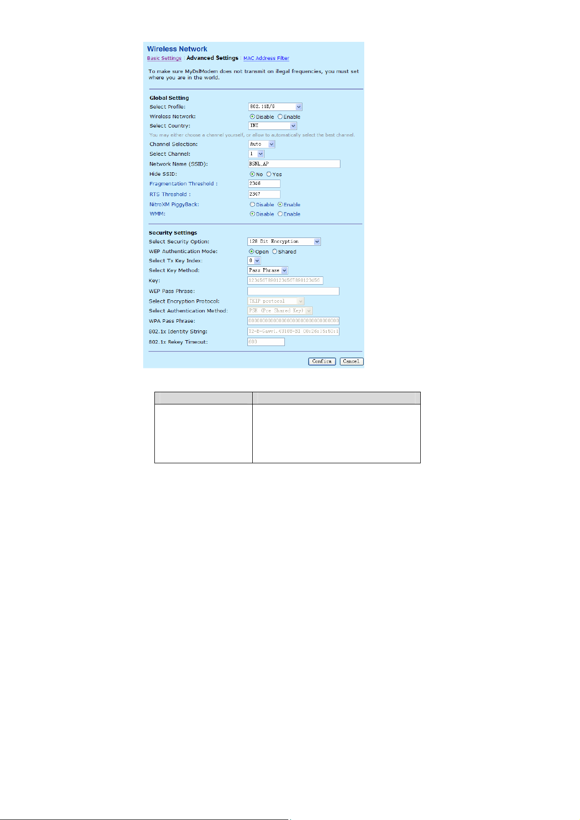
Step 1 In the Control Panel page, double click Network Connections. The
following page appears.
Step 2 Right click Wireless Network Connection, and select View Available
Wireless Networks.
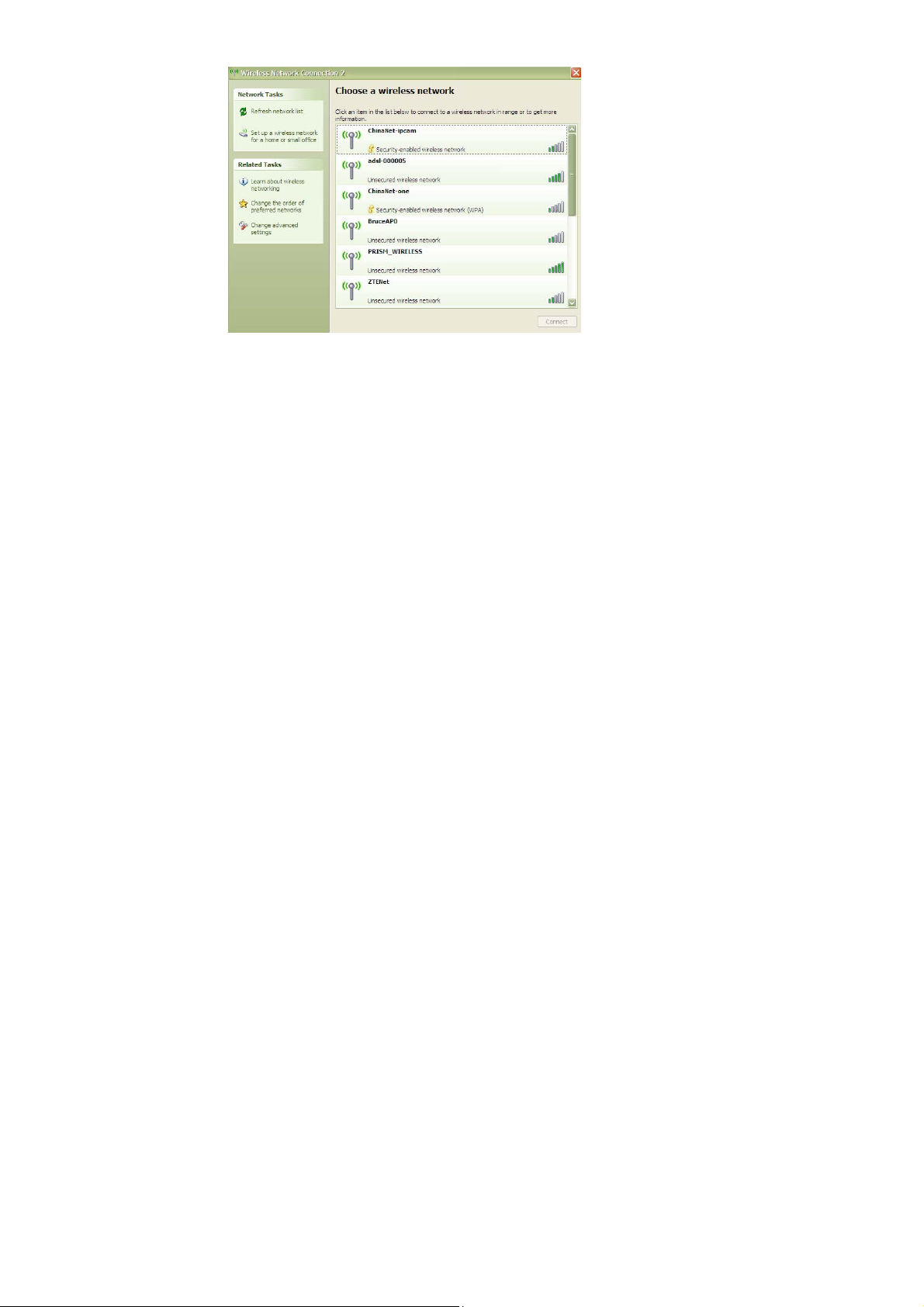
Step 3 In the Wireless Network Connection page, refresh the network lists
and select the network name (SSID) PRISM_WIRELESS, which is the
default SSID name. Then click Connect.
Teracom Limited 22 An ISO Certificed Company
User Manual for T2-B-Gawv1.4U10Y.BI
After finishing the settings, you can manage the modem through graphical user
interface (GUI) or Telnet.
3.4.2 Internet Connection
This page displays the information of the PVC after some effective configuration.
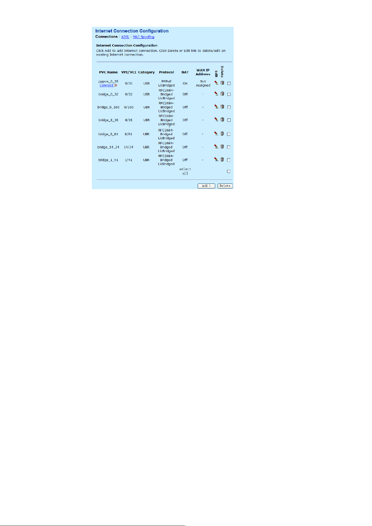
3.4.2.1 Connections
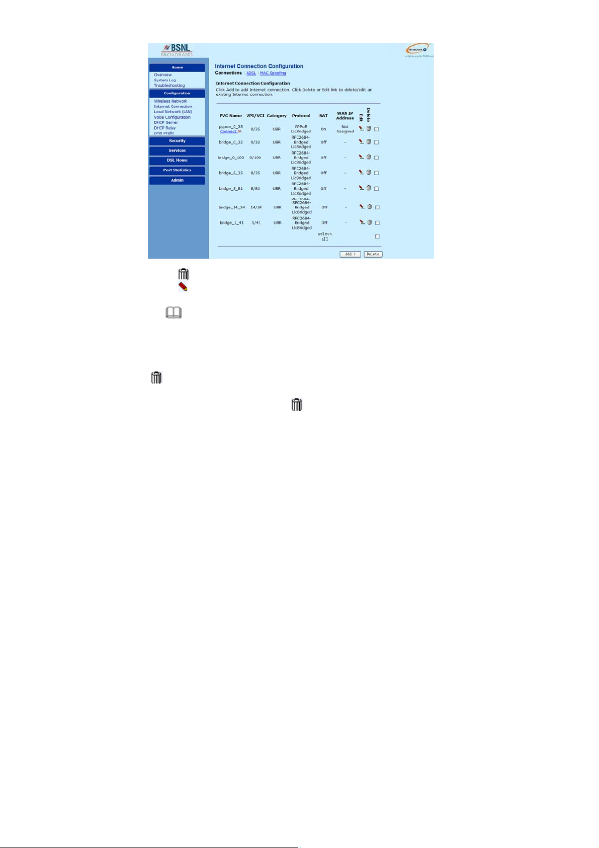
Choose Configuration > Internet Connection and the following page appears. In
this page, you can view the information of the PVC.
Teracom Limited 23 An ISO Certificed Company
User Manual for T2-B-Gawv1.4U10Y.BI
: Delete an existing Internet connection.
: Modify an existing Internet connection.
Note:
In the Connections page, the default configurati on of the mode m supports six
PVCs. The modem can be configured with eight PVCs at most. If you add more
than eight PVCs, it refuses to add.
: Delete an existing Internet connection.
The following describes an example of deleteing bridge_0_32.
Step 1 In the following page, click
Teracom Limited 24 An ISO Certificed Company
to delete bridge_0_32.

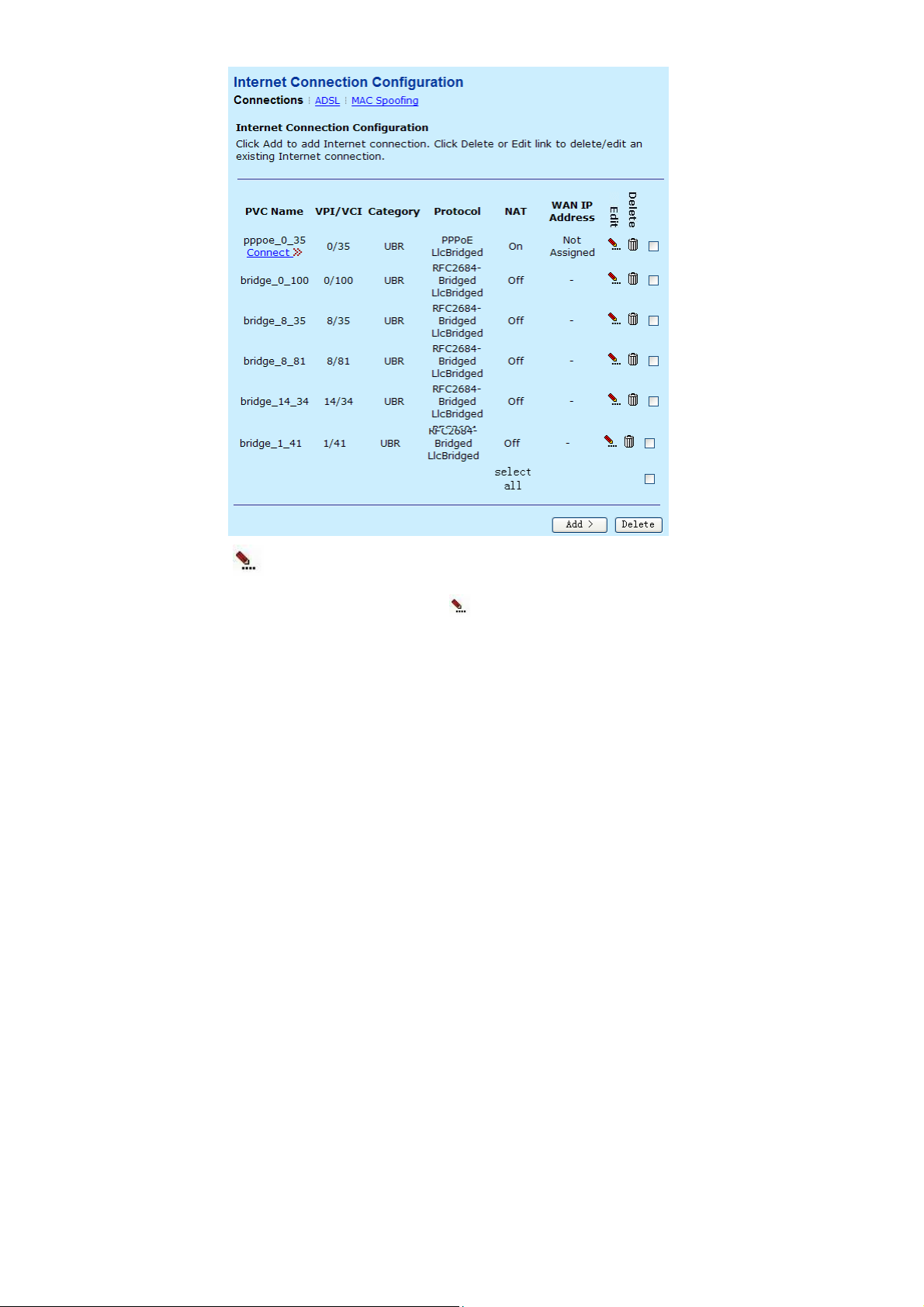
User Manual for T2-B-Gawv1.4U10Y.BI
Step 2 The system deletes bridge_0_32. After the deletion, the following page
appears.
Teracom Limited 25 An ISO Certificed Company
User Manual for T2-B-Gawv1.4U10Y.BI
: Modify an existing Internet connection.
The following describes an example of modifying bridge_8_35.
Step 1 In the following page, click
Teracom Limited 26 An ISO Certificed Company
to modify bridge_8_35.
User Manual for T2-B-Gawv1.4U10Y.BI
Step 2 The following page appears. In this page, you can modify VPI, VCI and
service category.
Teracom Limited 27 An ISO Certificed Company
 Loading...