


Terabeam Gigalink
Field Installation and Service Manual
Version 2.1
September, 2002
THIS DEVICE COMPLIES WITH PART 15 OF THE FCC RULES. OPERATION IS SUBJECT
TO THE FOLLOWING TWO CONDITIONS. (1) THIS DEVICE MAY NOT CAU SE HARMFUL
INTERFERENCE, AND (2) THIS DEVICE MUST ACCEPT ANY INTERF ERENCE RECEIVED,
INCLUDING INTERFERENCE THAT MAY CAUSE UNDESIRED OPERATION.
IF THIS PRODUCT IS SUSPECTED OF CAUSING HARMFUL INTERFERENCE WITH
OTHER EQUIPMENT, DISCONTINUE OPERATION I MMEDIATELY AND CONTACT
TERABEAM.
FCCID # O2700001-30-30


Table of Contents
Page
1 Introduction 1-1
Gigalink Product Family 1-1
Reliability 1-1
Gigalink Model XXX Description and Specifications 1-2
FCC Compliance Statement 1-4
2 Gigalink Installation Quick Guide 2-1
Unpacking the Kit and Verifying Components 2-2
Gigamon Software Installation 2-4
System Requirements 2-4
Gigamon Setup and Installation Procedure 2-5
Electrical Services 2-6
Network Interfaces 2-8
Mechanical Installation 2-11
Selecting the Optimum Terminal Mounting Method 2-15
Rough Mechanical (Visual) Alignment 2-16
Final Terminal Alignment 2-16
Radio Terminal Power-Up 2-17
Using Gigamon Software for Precision Alignment 2-18
Verifying Network Operation 2-22
3 Gigamon Software 3-1
Descriptions of Gigamon Components and Their Functions 3-2
Terminology 3-3
Color Convention 3-3
Components of the Main Window 3-3
Triggering Parameters and Threshold Setting Dialog Box Details 3-12
4 Terminal Maintenance and Troubleshooting 4-1
Maintenance 4-1
Troubleshooting 4-1
Recommended Troubleshooting Steps 4-14
5 Terabeam Technical Assistance 5-1
Table of Contents iii
Terabeam Gigalink Field Installation and Service Manual
Document Number: 045-1032-0000 / Revision: Draft
Release Date: TBD / Print Date: 12/10/02
Proprietary and Confidential


1 Introduction
Gigalink Product Family
The Terabeam® Gigalink millimeter wave radio system represents an entirely new
approach to broadband communications. Based on our extensive experience with millimeter
wave systems for military and research applications, we now apply these techniques to a
commercially priced version with our ultra-broadband family of Gigalink radio products.
The Gigalink broadband radio system operates in the FCC Part 15.255 unlicensed band
covering a frequency range of 57.05 – 64.0 GHz. Due to the unlicensed status of this band,
FCC license or special authorization is not required to operate our Gigalink systems. In
addition, the high atmospheric absorption of RF energy at this frequency virtually eliminates
any chance of interference from competing systems or unauthorized interception of the
broadcast signal.
The installation procedures detailed within this guide are similar to those used to install any
wireless system. In fact, certain attributes of the 57.05 – 64.0 GHz band actually simplify
deployment. The key to any successful installation project is proper planning and design. The
Gigalink radio product has been designed for ease of installation and trouble-free operation.
We recommend that you read and fully understand this guide prior to initiating the actual
installation work.
As stated above, the key to successful installation is proper system planning and execution.
As with most wireless systems, the Gigalink radio system requires un-obstructed Line of
Sight (LOS) to operate reliably. Because of the extremely high data bandwidth provided by
the Gigalink system (1.25Gbps) it is likely that our radio systems will be utilized as a critical
or primary network connection. This absolute reliance on our systems for connectivity
demands a focused attention to detail in order to assure un-interrupted operation.
Reliability
All Gigalink products are designed to provide a minimum statistical path availability of
99.99% (BER < 1 x 10
Exceeding the specific model range restrictions will result in unreliable operation particularly
during adverse weather.
Statistical availabilities in excess of 99.99% may be achieved by choosing the next longer
range system for a given path or by co-locating two Gigalink systems. Traditional circuit
redundancy methods utilizing collapsible ring architectures or media diversity may also
increase statistical availability.
–9)
when operated within the recommended range envelope.
Chapter 1 Introduction 1-1
Terabeam Gigalink Field Installation and Service Manual
Document Number: 045-1032-0000 / Revision: Draft
Release Date: TBD / Print Date: 12/10/02
Proprietary and Confidential
Gialink Model 6451e Specifications
Data Transmission
Bit Rate 1.25Gbps Full Duplex
Protocol Gigabit Ethernet (1000BaseFX)
Interfaces
Data FC Connector (850-nm MMF)
Monitor/Management (Ethernet) RJ-45 Connector and FC Connector (1310nm MMF)
DC Power Proprietary 3 terminal DC Receptacle and Connector Kit
Operational Parameters
Frequency Range 57.05 – 64 GHz
Output Power 10mW (antenna injection)
Antenna Type Integral 13” parabolic
Antenna Gain 40dBi, Min.
Beam Width 1.0o , Max.
Regulatory Compliance
Electrical CE – 60950 (Pending)
Electromagnetic FCC – Part 15.255, Certification #O2700001-30-30
CE – EMC and R&TTE Directive (Pending)
Power
DC Input Voltage -48 VDC +/- 20%
Maximum DC Input Current 1.5 Amperes
DC Power Consumption 75 Watts
Environmental
Operating Temperature -20°C to 50°C (-4°F to 122°F)
Storage Temperature -30°C to 85°C (-22°F to 185°F)
Relative Humidity Up to 95%, Non-Condensing
Mechanical
Transceiver H x W x D 33 x 33 x 20 cm (13.0 x 13.0 x 7.9 in.)
Transceiver Weight 17 lbs (7.7 kg)
FCC Complia nce Statement
The Terabeam Gigalink family of products is type-certified for unlicensed operation in
compliance with FCC Part 15.255. Terabeam Gigalink radio products are factory set for
frequency, frequency stability and transmitter power levels. No user-authorized adjustments
are provided. Changes or modifications not expressly approved by the party responsible
for compliance will void the user’s authority to operate this equipment.
For detailed information on Gigalink Part 15.255 type certification and rules governing Part
15 Unlicensed operation, please visit the Federal Communications Commission home page at
http://www.fcc.gov
1-2 Chapter 1 Introduction
Terabeam Gigalink Field Installation and Service Manual
Document Number: 045-1032-0000 / Revision: Draft
Release Date: TBD / Print Date: 12/10/02
Proprietary and Confidential
2 Gigalink Installation Quick Guide
The Terabeam Gigalink millimeter wave radio system represents an entirely new approach to
broadband communications. Based on our extensive experience with millimeter wave
systems for military and research applications, we now apply these techniques to a
commercially priced version with our ultra-broadband family of Gigalink radio products.
The Gigalink broadband radio system operates in the newly allocated unlicensed band
occupying the frequency range of 57.05 – 64.0 GHz. Due to the unlicensed status of this
band, FCC license or special authorization is not required to operate our Gigalink systems.
In addition, the high atmospheric absorption of RF energy at this frequency virtually
eliminates any chance of interference from competing systems or unauthorized interception
of the transmitted signal.
The installation procedures detailed within this guide are similar to those used to install any
wireless system. In fact, certain attributes of the 57.05 – 64.0 GHz band actually simplify
deployment. The key to any successful installation project is proper planning and design. The
Gigalink radio product has been designed for ease of installation and trouble-free operation.
We recommend that you read and fully understand this guide prior to initiating the actual
installation work.
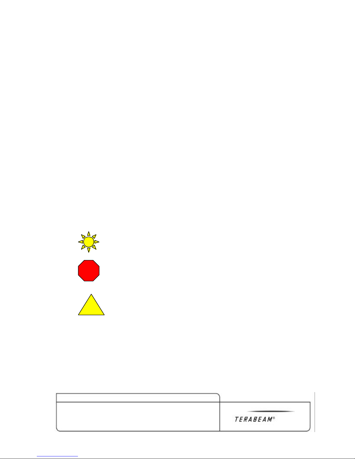
Throughout this guide, important topics, instructions or warnings are identified by symbols
notated by the following.
Indicates time saving recommendations
STOP
Indicates potential for equipment damage, or unsatisfactory
operation
Identifies areas of safety hazards or potential injury
!
Chapter 2 Gigalink Installation Quick Guide 2-1
Terabeam Gigalink Field Installation and Service Manual
Document Number: 045-1032-0000 / Revision: Draft
Release Date: TBD / Print Date: 12/10/02
Proprietary and Confidential

Unpacking the Kit and Verifying Contents
Your Gigalink system will arrive in two separate boxes, one containing the high band radio
terminal, DC Connector kit, mounting hardware and documentation and one containing the
low band radio terminal, DC Connector kit, mounting hardware and documentation. The
contents of both boxes should be identical with the exception of the fiber optic loop-back
cable, supplied only with one terminal.
Item/Description Qty Supplied Re-Order #
1. Gigalink Radio Transceiver 1 Same as Model #
3. Fiber Loop-Back Jumper 1 SFOFC-01
4. 10BaseT SNMP Adaptor Cable 1 3028
6. Pipe Mount L-Bracket 1 2842-1
7. Terminal Mount Hardware Kit (stainless) 1 2901
8. Gigalink Installation/Operation Manual 1 (not shown)
2-2 Chapter 2 Gigalink Installation Quick Guide
Terabeam Gigalink Field Installation and Service Manual
Document Number: 045-1032-0000 / Revision: Draft
Release Date: TBD / Print Date: 12/10/02
Proprietary and Confidential

With receipt of system delivery, each carton should be inspected to confirm complete
content. If any items are found to be missing, installers should contact the factory to arrange
delivery.
Chapter 2 Gigalink Installation Quick Guide 2-3
Terabeam Gigalink Field Installation and Service Manual
Document Number: 045-1032-0000 / Revision: Draft
Release Date: TBD / Print Date: 12/10/02
Proprietary and Confidential

NOTE: During shipping kit inspection, do not remove the contents of Gimbal Mount
#2289 or Hardware kit #2901 in order to avoid mixing-up or loosing the hardware.
Gigamon Software Installation
The SNMP is accessed through the Gigamon™ Graphic User Interface (GUI). The Gigamon
Interface is the primary tool for precision alignment of the Gigalink terminals. Through
Gigamon, the SNMP utility is also used to set terminal configurations and provide ongoing
monitoring of critical radio parameters.
Before proceding with terminal installation the Gigamon GUI application must be installed
on the technician’s laptop computer.
NOTE: Installing the Gigamon monitoring software in two laptop computers will
simplify precision alignment. If two laptops with Ethernet cards are available, it is
recommended that both receive the software.
System Requirements
For proper operation of the Gigamon monitoring utility the following minimum system
requirements must be met.
1. Computer running Windows NT/2000, 2000ME or Windows XP
2. A 10/100 Ethernet Adapter card, installed in the computer.
3. Screen resolution should be 1024x768 or higher. To change screen resolution,
3.1 Click on ‘Start’ menu
3.2 Select ‘Settings’
3.3 Select ‘Control Panel’
3.4 Double click on ‘Display’ icon.
3.5 Click on ‘Settings’, and move the slider in ‘Screen Area’ to adjust the display
2-4 Chapter 2 Gigalink Installation Quick Guide
Terabeam Gigalink Field Installation and Service Manual
Document Number: 045-1032-0000 / Revision: Draft
Release Date: TBD / Print Date: 12/10/02
Proprietary and Confidential

Gigamon Setup and Installation Procedure
1. Insert the resource disc and double click on the “GigaMon Install” icon.
2. Run “setup.exe”. This will install the drivers in Windows System directory, copy main
executable file “GigaMon.exe” to the user’s specified path and add the program name to
program menu.
2.1 Copy W32N50.DLL to the Windows System directory, usually the appropriate
directory will be C:\WINNT\SYSTEM.
2.2 Copy “PCANDIS5.SYS” to the Windows System directory, usually the appropriate
directory will be C:\WINNT\SYSTEM.
2.3 Copy “moncfg.exe” to the preferred path.
At the conclusion of the Installation Session, a Gigamon Icon will be displayed on the
Computer desktop. Double clicking on this Icon will produce the window shown in Figure 3.
If problems are encountered during the Gigamon monitor software installation process, refer
to the more detail description of the Gigalink SNMP utility and Gigamon monitoring
software (sections 3 and 4) of the enclosed “Users Manual”.
Figure 3, Initial Gigamon Screen
Chapter 2 Gigalink Installation Quick Guide 2-5
Terabeam Gigalink Field Installation and Service Manual
Document Number: 045-1032-0000 / Revision: Draft
Release Date: TBD / Print Date: 12/10/02
Proprietary and Confidential
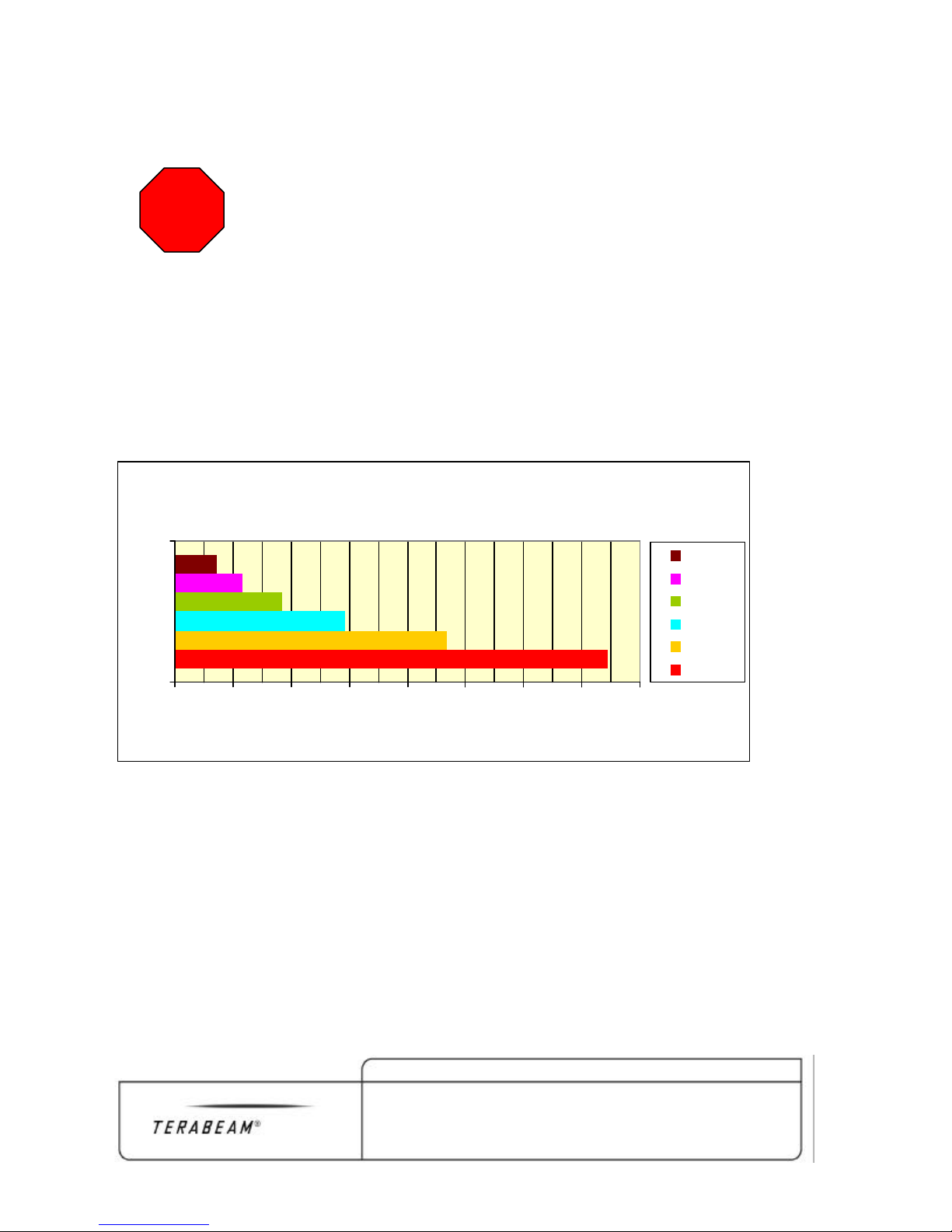
Electrical Services
Maximum Cable Length vs. Wire Gauge for Pioneer
STOP
WARNING: The Gigalink Radio Terminal electrical connection at the
radio terminal must be made first in order to avoid arcing and possible
damage to the radio terminal connector. Once the radio connection has
been made, power may be applied to the circuit.
Electrical Power
The Gigalink Model 6451e terminal operates on a single –48VDC supply. Power may be
provided from a regulated power supply or battery plant. The installer must provide a 3
stranded conductor DC power cable of a gauge sufficient for the intended application.
Installers should use the guide below to determine the minimum wire gauge needed based on
the length of the DC power cable run.
@ 20 degrees C Wire Temperature
22 Ga.
20 Ga.
18 Ga.
16 Ga.
Wire Gauge
14 Ga.
12 Ga.
0 100 200 300 400 500 600 700 800
Cable Length (feet)
2-6 Chapter 2 Gigalink Installation Quick Guide
Terabeam Gigalink Field Installation and Service Manual
Document Number: 045-1032-0000 / Revision: Draft
Release Date: TBD / Print Date: 12/10/02
Proprietary and Confidential
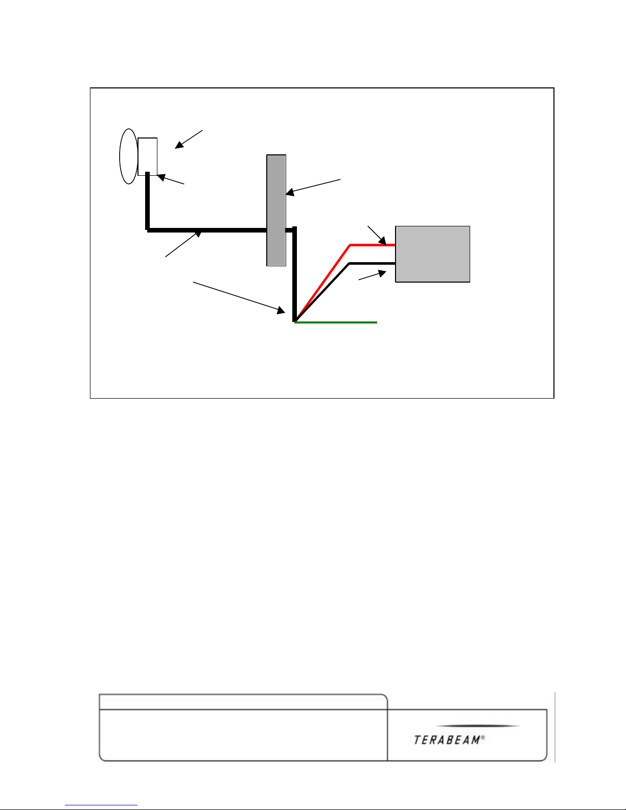
-48VDC
Green Power-on
Figure 5, DC Power Connections
GigaLink Terminal
Indicator
Wall or Roof Penetration
-48VDC Supply (Red)
Power cable Assembly
Power
Source
-48VDC Return (Black)
Building Ground
Network Interfaces
The Gigalink terminals utilize a weatherproof, FC type fiber connector on the radio terminal
and a proprietary 10BaseT interface for SNMP communications. Network Fiber must be
supplied to the radio terminal location and terminated in FC Male. The supplied Gigamon
adapter cable (Figure 1, Item 4) can be permanently installed for the SNMP network
connection by attaching a standard CAT 5 coupler and cable.
The Gigamon adapter cable is wired in a straight configuration to enable communication
directly with the installer’s laptop. For connection to a network switch, a length of cross
connect cable is necessary between the radio terminal and switch.
The IF Monitor port is provided for factory test and diagnostics only and should remain
capped in final installation.
The Network and SNMP interfaces are shown below.
Chapter 2 Gigalink Installation Quick Guide 2-7
Terabeam Gigalink Field Installation and Service Manual
Document Number: 045-1032-0000 / Revision: Draft
Release Date: TBD / Print Date: 12/10/02
Proprietary and Confidential

Chapter 2 Gigalink Installation Quick Guide 2-1
Terabeam Gigalink Field Installation and Service Manual
Document Number: 045-1032-0000 / Revision: Draft
Release Date: TBD / Print Date: 12/10/02
Proprietary and Confidential
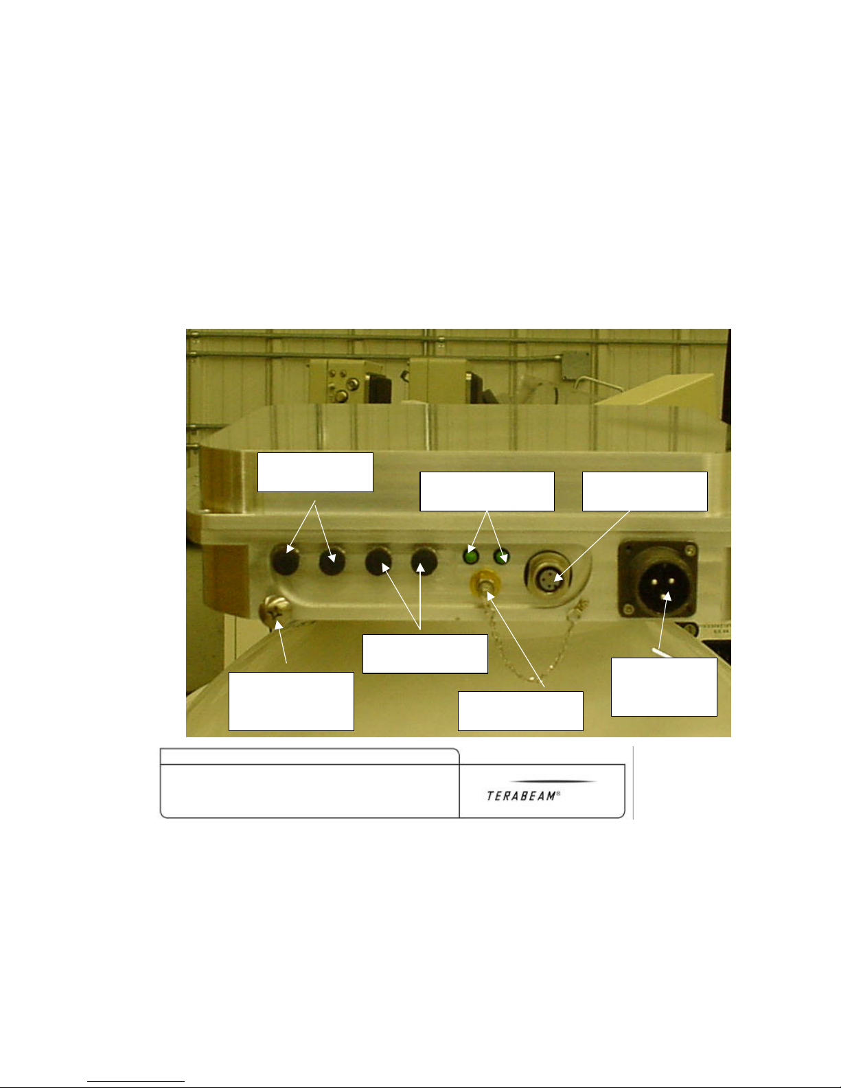
Figure 6, Terminal Power, Network and SNMP Interfaces
TX/RX Type FC
for Data Payload
TX/RX Type FC for
SNMP and Monitor
Proprietary 10BaseT
Copper Monitor Port
Power On/ Fuse status
LED Indicators
50ohm IF Monitor
Port, load and Chain
(3) Conductor
Mil-Style Power
Connector
Location of tapped
hole for terminal
ground lug


LED Operation Truth Table
LED Condition Terminal Status
Both Lit presence of -48VDC power and internal fuse OK
One Lit -48VDC present but internal fuse blown
None Lit No -48VDC power present
Mechanical Installation
Attaching the Gimbal Mount
Before actual terminal mounting can be accomplished, it is necessary to attach the Pan and
Tilt Gimbal Mount to the Gigalink radio terminal housing. The necessary hardware for this
attachment is provided with the Pan and Tilt Gimbal Mount # 2289-1 and consists of (4) M8
x 1.5cm stainless steel bolts, flat washers and lock washers. Figure 6, details the Gimbal
mounting procedure.
Chapter 2 Gigalink Installation Quick Guide 2-1
Terabeam Gigalink Field Installation and Service Manual
Document Number: 045-1032-0000 / Revision: Draft
Release Date: TBD / Print Date: 12/10/02
Proprietary and Confidential

Selecting the Optimum Terminal Mounting Method
Stainless Steel Bolts, ½” Minimum O.D.
The following sections detail available mounting methods and hardware for the Gigalink
product.
Figure 11, Standard Wall Mount
WARNING: It is the responsibility of the installer to assure that the
radio terminal is mounted securely enough to prevent falling.
!
Particular care must be used when wall mounting the radio terminal
above areas frequented by personnel. In some cases, it may be
advisable to attach a safety chain or lanyard through the gimbal mount
to provide additional security.
Pan and Tilt C Bracket (#2289)
“L” Bracket (#2842-1)
with wall anchors, or through bolt to
backing plate (specialized wall mount
Hardware not supplied)
Gigalink™ Transceiver
2-2 Chapter 2 Gigalink Installation Quick Guide
Terabeam Gigalink Field Installation and Service Manual
Document Number: 045-1032-0000 / Revision: Draft
Release Date: TBD / Print Date: 12/10/02
Proprietary and Confidential

Stainless Steel U- Bolts, Washers,
Figure 12. Standard Pipe Mount (all hardware included)
Pipe (structural steel) 2.5” – 4.5” OD
Gigalink™ Transceiver
C Bracket (#2289)
“L” Bracket (#2842-1)
Nuts (hardware kit #2901)
Rough Mechanical (Visual) Alignment
Once the Gigalink Radio Terminals are securely fastened to the mounting locations, the
installer should visually align the terminals. Visual alignment is accomplished by loosening
both the C Bracket Attachment bolts and L Bracket Mounting bolts slightly. With these (7)
bolts loosened the terminal can be aligned (aimed) toward the other terminal by sighting
along the radio housing body.
Once satisfied that both terminals are aimed at the each other, all seven bolts can be snagged
up enough just to hold the desired position.
Chapter 2 Gigalink Installation Quick Guide 2-3
Terabeam Gigalink Field Installation and Service Manual
Document Number: 045-1032-0000 / Revision: Draft
Release Date: TBD / Print Date: 12/10/02
Proprietary and Confidential

Final Terminal Alignment
NOTE: Alth ough it is possible for a single technician to perform final terminal
alignment. Terabeam recommends that two technicians with monitor-enabled
laptops be dedicated to this task. By dedicating two technicians equipped with
cellular phones or two-way radios, final alignment can be accomplished at both
terminal sites concurrently, eliminating the need to constantly travel between sites.
Radio Terminal Power-Up
Once the Radio terminals have been mechanically mounted in place and visually aligned,
both radio terminals must be powered up, and network services connected.
Terminal Power up
Power-up the Gigalink terminal as follows.
1. Attach DC power cord securely to the radio terminal
2. Attach power leads to –48VDC source Red to –48VDC supply, Black to –48VDC return
and Green to Building Ground.
3. Power up –48VDC circuit.
4. Verify power on condition via Green “Power-on” LED’s located on the bottom of the
terminal housing
Connecting Network Services
Once the power has been applied to the Gigalink terminal, Network services can be
connected and verified. The network Fiber connections to the Gigalink terminal are Type FC
male terminated fiber optic cables. Make these connections by aligning the connector body
index tab, then tightening the outer collar in a clockwise rotation.
In the network switch room, insert the other end of each fiber optic cable into the appropriate
TX and RX switch ports. If done correctly, a link light should be visible. If no link light is
visible, make sure the radio is powered up and swap the fibers.
2-4 Chapter 2 Gigalink Installation Quick Guide
Terabeam Gigalink Field Installation and Service Manual
Document Number: 045-1032-0000 / Revision: Draft
Release Date: TBD / Print Date: 12/10/02
Proprietary and Confidential

SNMP Monitor
GigaMon
Laptop
Using Gigamon Software for Precision Alignment
The Gigamon software previously installed in the technician’s laptop will be the primary tool
used for precision alignment. To initiate the Gigamon session, install the SNMP adaptor
cable between the laptop Ethernet adaptor and the proprietary 10BaseT connector on the
radio terminal.
Figure 13, Gigamon Adapter Cable Connection
Ethernet Port
Port
Chapter 2 Gigalink Installation Quick Guide 2-5
Terabeam Gigalink Field Installation and Service Manual
Document Number: 045-1032-0000 / Revision: Draft
Release Date: TBD / Print Date: 12/10/02
Proprietary and Confidential
Adapter Cable

Follow these steps to initiate the Gigamon alignment tool.
1. Double click the Gigamon Icon to launch the Gigamon utility.
Figure 14, Initial Gigamon Screen
2-6 Chapter 2 Gigalink Installation Quick Guide
Terabeam Gigalink Field Installation and Service Manual
Document Number: 045-1032-0000 / Revision: Draft
Release Date: TBD / Print Date: 12/10/02
Proprietary and Confidential

2. From the “Action” Menu select “Refresh”
Figure 15, Gigamon Screen “Refreshed”
Chapter 2 Gigalink Installation Quick Guide 2-7
Terabeam Gigalink Field Installation and Service Manual
Document Number: 045-1032-0000 / Revision: Draft
Release Date: TBD / Print Date: 12/10/02
Proprietary and Confidential

3. From the “Action” Menu select “Align” then “Run”
Figure 16, Gigamon in “Alignment Run” Mode
Highest Receive level
achieved
(magenta band)
Blue Bar Indicates
Current Receive Level
When in the “Align”, “Run” mode the Gigamon monitor displays a continually updated
receive level. The task during precision alignment is to maximize or peak the receive level.
Precision alignment is made in both the vertical and horizontal plane (up and down, left and
right) separately, one terminal at a time.
Begin alignment by aiming the radio terminal slowly up while observing the change in
receive level. Typically, the receive level will rise, then fall and then rise again slightly on
both sides of the optimum alignment as the receiver moves from the center main beam to the
edge side-lobes of the radiation pattern. It is recommended that the technician move the
alignment through the main lobe and into both side-lobes until returning to the center peak
2-8 Chapter 2 Gigalink Installation Quick Guide
Terabeam Gigalink Field Installation and Service Manual
Document Number: 045-1032-0000 / Revision: Draft
Release Date: TBD / Print Date: 12/10/02
Proprietary and Confidential

receive level. When satisfied that the maximum receive level has been reached, tighten the
Gimbal side adjuster bolts to hold the desired vertical alignment angle. To facilitate this task,
Gigamon displays the highest receive level recorded as a magenta bar at the top of the
receive level bar.
Repeat this procedure for the Azimuth (Horizontal) alignment by slightly loosening the
Gimbal base mounting bolts and rotating the alignment from right to left. Again, by
observing changes in the receive level monitor, identify both side-lobe areas and return the
alignment to the center “Peak” position.
Repeat the previous two alignment procedures at the other Gigalink terminal while
maintaining the position of the original terminal. During these procedures, the receive level
should continuously improve. Optimum terminal alignment is best accomplished by small
adjustments at both terminal sites.
NOTE: Precision alignments are made most easily by make very slight incremental
adjustments to the radio alignment. Care must be taken not to over-adjust the
alignment. To facilitate precision alignment, tighten all adjusting bolts to allow
movement only when bumping terminal firmly with your hand.
An acceptable receive level will be indicated by the Blue Gigamon receive level indicator as
a level approaching the Maximum recorded receive level (Magenta line) and as a level falling
somewhere in the upper half of the green region behind the blue indicator bar. An acceptable
numeric measure would be a level above 450 as indicated by the large level number
displayed below the receive level indicator.
When satisfied that optimum alignment has been achieved, tighten the (3) Gimbal base
mounting bolts and the (4) Gimbal side adjuster bolts to secure the desired position.
As a final installation step, perform the “Save GigaMon Information in a File as” operation
as prompted when exiting the application. The saved radio parameter information can be
used for future comparisons to gauge ongoing radio performance.
Verifying Network Operation
Once an acceptable (optimum) receive level has been achieved, the Gigalink system will
provide an error free RF link between the two network devices at both sites. If no link is
obtained, check the network fiber, routing table configurations and other network parameters.
If an error free link still cannot be established, consult the Troubleshooting/Diagnostic
section of the Gigalink User’s Manual.
Chapter 2 Gigalink Installation Quick Guide 2-9
Terabeam Gigalink Field Installation and Service Manual
Document Number: 045-1032-0000 / Revision: Draft
Release Date: TBD / Print Date: 12/10/02
Proprietary and Confidential


3 Gigamon Software
1. Run “setup.exe” from installation diskette or resource disc. This setup program will copy
the following files into your system.
1.1.W32N50.DLL in Windows System directory, it is “C:\WINNT\SYSTEM32 “ for
Windows NT/2000 and “C:\WINNT\SYSTEM32 “ for Windows 9x.
1.2.PCANDIS5.SYS (for Windows NT/2000) or PCANDIS3.VXD (for Windows 9x) in
Windows System directory.
1.3.The main executable Gigamon.exe in the "preferred path” (the path selected by user
during setup program).
1.4.The help file Gigamon.chm in the “preferred path\Hlp” directory.
1.5. The uninstaller file “Uninst.isu” in the “preferred path” so that the user can uninstall
Gigamon from the list in “Add/Remove Programs” of “Control Panel”.
1.6. A desktop shortcut and the program name in the program menu. You need to
restart your computer before running Gigamon.exe for the driver
PCANDIS5.SYS or PCANDIS3.VXD to be loaded.
2. Connect computer’s Ethernet card with the Gigalink radio terminal 10BaseT terminal
with the supplied SNMP Adapter Cable.
3. Power up the Gigalink terminal by connecting AC power and the DC power cable.
4. Double Click the “Gigamon” Icon to run the program.
Chapter 3 Gigamon Software 3-1
Terabeam Gigalink Field Installation and Service Manual
Document Number: 045-1032-0000 / Revision: Draft
Release Date: TBD / Print Date: 12/10/02
Proprietary and Confidential

Initial Screen
Descriptions of Gigamon Components and Their Functions
The main function of Gigamon is to detect all the Gigalink terminals connected within the
same network (connected via hub/switches) and to configure/monitor their parameters.
Gigamon will detect and read the parameters of multiple Gigalink terminals (up to 8) at the
same time, but it configures/monitors only the Gigalink currently selected. After selecting
‘Refresh’ from the ‘Action’ menu, the first Gigalink detected becomes the currently selected;
all the components of the main window display the parameter values of the currently selected
Gigalink terminal. The user can select another Gigalink terminal by clicking on option
“Select Gigalink” in “File” menu and selecting that terminal from the list displayed.
3-2 Chapter 3 Gigamon Software
Terabeam Gigalink Field Installation and Service Manual
Document Number: 045-1032-0000 / Revision: Draft
Release Date: TBD / Print Date: 12/10/02
Proprietary and Confidential

Before going into the operating details, some terminology, and the color convention used
should be explained.
Terminology
• ‘Monitoring’ is an action state defined as ‘Runmode’/’Alignment’ and/or reading current
Gigalink terminal parameters. ‘Runmode’ is the state where Gigamon reads the Gigalink
terminal parameters (specially for Rx Power/Receive Level) while continuously updating
the display.
• ‘Setting Network Parameters” ,“Setting Threshold Parameters” and “Setting Factory
Parameter” are all part of “Configuring Gigalink”. Setting a parameter means saving that
value in Gigalink terminal’s EEPROM image, once saved the terminal will keep the new
values even if Gigalink terminal is powered off and back on.
Color Convention
The status colors of the Gigamon display are:
• Black Unknown
• Green Safe range/On/Running
• Red Danger range/Off/Stopped
• Yellow Warning range
• Blue Current/Latest read Value
• Grey Read-Only
Components of the Main Window
• MAC Address: The MAC or Hardware address off the Gigamon utility resident in the
Gigalink terminal. This unique address is set at the factory and cannot be changed.
Initially the Gigamon program does not know this MAC address of the connected
Gigalink(s), and so the value “Unknown” is displayed. When ‘Refresh’ is selected from
Action menu, the program tries to get the MAC addresses of all the Gigalink terminals
connected to the network segment, and then ‘Unknown’ value becomes the MAC address
of the first Gigalink terminal MAC address detected. By default, the first Gigalink
terminal detected during refresh becomes the “Currently Selected” Gigalink.
• Serial Number: This value is set at the factory and cannot be changed. The value
displayed, also corresponds to the currently selected Gigalink.
Chapter 3 Gigamon Software 3-3
Terabeam Gigalink Field Installation and Service Manual
Document Number: 045-1032-0000 / Revision: Draft
Release Date: TBD / Print Date: 12/10/02
Proprietary and Confidential

• Synthesizer, PLL, TX Link, and RX Link: These are discrete values that indicate an
acceptable or unacceptable state for critical monitoring points within the Gigalink radio
terminal. The rectangles associated with the Synthesizer and PLL Lock display green if
they are locked (acceptable), or display red if unlocked (unacceptable). The rectangles for
Tx Link and Rx Link are green if an optical signal is present on the fiber segment, and
turn red if no signal is present.
• Rx Power: In “Align/Run” mode, the blue rectangle represents current Receive Level. If
‘Run’ is chosen from the ‘Align ’ submenu of ‘Action’ menu, it starts displaying this
value continuously. A higher Rx Power indicates better alignment. As the user does
adjustment in “Run” mode changing the Gigalink terminal alignment, Rx Power varies. A
magenta, horizontal, line is displayed on the top of the blue receive level rectangle
indicates the highest/maximum value reached so far. A numeric value of the maximum
receive level is displayed adjacent to the magenta line. The blue inner rectangle
represents the current value. The current Rx Power’s numeric value is also shown below
the rectangle in a large font to facilitate alignment with higher visibility.
• 6 Volt, 15 Volt, -15 Volt, Vtune, Gunn: These are other variable values. During
‘Refresh’ and ‘Run’, Gigamon retrieves the current values and displays these values as a
blue horizontal line. These rectangles are divided into safe, warning and danger regions.
If the current value is the optimum then the blue line should be at the middle. For 6 Volt
rectangle, the optimum value is 6.10, top to middle, or bottom to middle is the 10% of
optimum value, and so, for 6 volt top=6.1+(0.61*1)=6.71, and bottom=6.1(0.61*1)=5.49. For all others, top to middle, or bottom to middle is 40% of the optimum
value. So for 15 Volt, the optimum value is 15.0, top=15.0+(1.5*4)= 21.0, bottom=15.0-
6.0=9.0. The optimum values of –15 Volt, 24 Volt and Gunn are 15.0, 24.0, and 850
respectively.
• Status bar: The status bar at the bottom of the screen is for displaying current status,
error, and some numeric values. Errors and status are shown at the left, and values at the
right. Most importantly, during refresh, it shows the numeric value of all variable
parameters.
• Menu:
1. File Menu: The ‘File’ menu has following options:
− ‘Select Gigalink’ to open the “Select Current Radio/Gigalink” dialog box as
shown below.
3-4 Chapter 3 Gigamon Software
Terabeam Gigalink Field Installation and Service Manual
Document Number: 045-1032-0000 / Revision: Draft
Release Date: TBD / Print Date: 12/10/02
Proprietary and Confidential

“Select Current Radio/ Gigalink” Screen
The “Select Current Radio/Gigalink” window displays the factory-set parameters
of the currently selected/active Gigalink at the top and a combo box (list) of MAC
addresses for all the Gigalink terminals found. Choosing a different MAC address
from the combo list updates serial number field with corresponding value for that
terminal. If ‘Select’ and then ‘OK’ buttons are pressed then Gigamon selects
only the radio with the MAC address currently selected in “Gigalink Radio
MAC Address” combo box as the currently selected/active Gigalink. Pressing
‘Cancel’ button after ‘Select’ undoes the selection and keeps previous selection
of currently active radio.
− ‘Save Info As’ to open a dialog box “Save Gigalink Info in a File As” for the
user to select a text filename to save all the parameters for all the Gigalink
terminals detected. The dialog box shows the default filename as “Gigalink.txt”.
The user can type/select any filename and save to any location. Gigamon will
create the file if does not exist or open the file without deleting old data if it
already exists.
Chapter 3 Gigamon Software 3-5
Terabeam Gigalink Field Installation and Service Manual
Document Number: 045-1032-0000 / Revision: Draft
Release Date: TBD / Print Date: 12/10/02
Proprietary and Confidential

“Save Gigalink Info in a file as’ Screen
The “Save Gigalink Info” command will write/append a line of parameter values
for each Gigalink terminal detected in the current session. These values are tab
delimited, and so they can be copied and pasted into an Excel spreadsheet. Each
line/record has timestamps (date and time) with seconds resolution so the saved
file may have several lines for the same Gigalink terminal if appending to an
existing file or the user chooses ‘Save Info As’ several time during the current
session. But the time-stamp will be unique for each line. The file content will be
saved in the format shown below:
3-6 Chapter 3 Gigamon Software
Terabeam Gigalink Field Installation and Service Manual
Document Number: 045-1032-0000 / Revision: Draft
Release Date: TBD / Print Date: 12/10/02
Proprietary and Confidential

Format of “Save Gigalink Info” file
The Left portion of the “Save Gigalink Info” file data
The Right portion of the “Save Gigalink Info” file data
− The “Select Ethernet Adaptor” window appears by menu option ‘File->Select
Ethernet Adapter’. It also appears when program is launched if multiple network
adapters are found in the computer.
It displays the device names and descriptions for all of the network adapters
detected by Gigamon. If ‘Select’ and then ‘OK’ buttons are pressed then
Gigamon recognize only the Ethernet adaptor chosen.
Chapter 3 Gigamon Software 3-7
Terabeam Gigalink Field Installation and Service Manual
Document Number: 045-1032-0000 / Revision: Draft
Release Date: TBD / Print Date: 12/10/02
Proprietary and Confidential

‘ “Select Ethernet Adapter” dialog box
− The ‘File->Exit’ command closes the application, but before exiting initiates the
‘Save Info As’ to prompt the user to save the retrieved data if desired.
2. The ‘Settings’ menu has the following options:
− The “Factory Settings” command is used to set read only information such as
serial number, MAC address, Version number, and Manufacture date. This option
is for factory use only and remains disabled for the non-factory user.
− The ‘Network and Security’ option from ‘SNMP’ submenu of ‘Settings’ menu
opens “Network and Security Settings” dialog box for writing/setting SNMP
Network configuration to the Gigalink terminal currently selected.
3-8 Chapter 3 Gigamon Software
Terabeam Gigalink Field Installation and Service Manual
Document Number: 045-1032-0000 / Revision: Draft
Release Date: TBD / Print Date: 12/10/02
Proprietary and Confidential

“Network and Security Settings” Screen
This dialog box displays the MAC and serial number of the currently selected
Gigalink as read-only text. It also shows the current (Factory default) values of
the following SNMP related settable/configurable parameters:
− Gigalink SNMP Agent IP: This value is needed for any SNMP monitoring
software to request a Gigalink for any SNMP variable’s value or to change value
(SNMP Get/Set functions). It is also needed for SNMP monitoring software to
distinguish the source of any SNMP trap packet sent by any Gigalink terminal. It
may also be required for many other network activities like pinging a Gigalink
terminal since this communication protocol uses IP packets. An IP-Address/Net-
Mask consists of 4 octets separated by dots and each octet’s range is 0 to 255.
Chapter 3 Gigamon Software 3-9
Terabeam Gigalink Field Installation and Service Manual
Document Number: 045-1032-0000 / Revision: Draft
Release Date: TBD / Print Date: 12/10/02
Proprietary and Confidential

− Subnet Mask, and Gateway IP: These parameters define which IP address range
will be local for the Gigalink terminal. When the Gigalink terminal sends an IP
packet, it does logical AND between this Subnet Mask and destination IP address
to find out if the destination is in its local subnet. The Gigalink terminal needs to
know the local “Subnet Mask” because if the destination is not within its local
network, the Gigalink terminal will send the packet to the default destination, the
Gateway, which is a router. For this reason, the Gateway/router’s IP address must
be defined as well.
− SNMP Manager IP: The Gigamon user must define the IP address of the
computer/host acting as SNMP Manager so that Gigalink terminal can send
SNMP traps to the host.
− Report Frequency: The Gigamon user must define how frequently each radio
terminal will send SNMP trap packets to the SNMP Manager reporting the status
of the SNMP variables. The combo box gives list of report intervals to choose
from. If ‘Unknown’ is chosen, pressing ‘Apply’ button will send the new
parameter values to the currently selected Gigalink and write that value into
Gigalink terminal EEPROM image.
− SNMP ‘Get’/’Set’ Operations: The parameters 'Community String', 'Net' and
'Mask' ensure security of the SNMP 'Get'/'Set' operations. The Gigalink matches
the 'Community String' in the SNMP manager's 'Get'/'Set' request packet, and also
checks if the SNMP manager's IP address is within the range that is defined by
'Net' and 'Mask'. If any of these validations fail, the Gigalink terminal will not
respond to the request. 'Community String', 'Net' and 'Mask' can be different for
'Get' and 'Set' operations.
− Community string: The “Community String” is like a password for the SNMP
'Get'/'Set' operation. If a community string is set, then the SNMP manager needs
to provide it to the Gigalink terminal if sending 'Get'/'Set' request. When the
Gigalink terminal receives a request, it will match this string. If the match fails,
the Gigalink terminal will not send requested parameter(s) values back to the
SNMP manager on 'Get' request, and will not change its parameter values on 'Set'
request. This string must be alphanumeric and no longer than 16 characters.
− Net and Mask: These two parameters define the range of IP addresses acceptable
to the Gigalink terminal when responding to SNMP 'Get'/'Set' requests. The
format is x.x.x.x where x is a digit from 0 to 255. For example, if 'Net' is defined
as 10.0.0.0 and 'Mask' as 255.255.255.0, then the range of IP addresses the
Gigalink terminal will accept is 10.0.0.x where x = 1.254.
3-10 Chapter 3 Gigamon Software
Terabeam Gigalink Field Installation and Service Manual
Document Number: 045-1032-0000 / Revision: Draft
Release Date: TBD / Print Date: 12/10/02
Proprietary and Confidential

− Defaults: The ‘Defaults’ button is not available for users. This is used for
initializing the above parameters at the Harmonix factory.
− The ‘Threshold and Trigger’ option from ‘SNMP’ submenu of ‘Settings’ menu
opens the dialog box “Triggering Parameters and Setting Thresholds”.
“Triggering Parameters and Setting Threshold” Screen
These settings trigger parameters on/off and define the threshold range for the triggered
parameters. The Gigalink terminal monitor will send the SNMP Host/Manager an SNMP
alert trap when a trigger-enabled parameter goes beyond the set threshold range.
Checking an item’s box will activate that parameter to be monitored against threshold
ranges or an on/of condition. When the ‘Apply’ button is clicked the setting is written to
the Gigalink terminal EEPROM. The description of each parameter and their
corresponding threshold values are given below.
Chapter 3 Gigamon Software 3-11
Terabeam Gigalink Field Installation and Service Manual
Document Number: 045-1032-0000 / Revision: Draft
Release Date: TBD / Print Date: 12/10/02
Proprietary and Confidential

Triggering Parameters and Threshold Setting Dialog Box Details
• 6 Volt: A power supply voltage. Enter ‘Low’ for low threshold ranging (5.6 to 6.1), and
enter ‘High’ for high threshold ranging (6.1 to 6.5). The optimum value is 6.1 volt.
• +15 Volt: A power supply voltage. Enter ‘Low’ for low threshold ranging (10 to 15), and
enter ‘High’ for high threshold ranging (15 to 20). The optimum value is 15.0 volt.
• –15 Volt: A power supply voltage. Enter ‘Low’ for low threshold ranging (10 to 15), and
enter ‘High’ for high threshold ranging (15 to 20). The optimum value is 15.0 volt. ‘-15’
is only the name of this parameter, and all threshold values related to this parameter are
set positive.
• VTune: Varactor tuning diode voltage. Sampling this voltage provides another
monitoring point for transmitter source stability. Vtune will typically fall between 4 and 7
Volts and may vary slightly during normal operation. Wide variations in varactor voltage
beyond the initial reading may indicate a tuning problem with the fundamental GUNN
diode oscillator source. The Vtune parameter does not offer a default threshold setting
option nor will it trigger an alarm trap in response to changes to this reading.
• Gunn: The Gunn Oscillator current. Enter ‘Low’ for low threshold ranging (590 to 850),
and enter ‘High’ for high threshold ranging (850 to 1300). The optimum value is 850
milliamps.
• Rx Power: The receive level. Enter ‘Low’ for low threshold ranging (300 to 600), and
enter ‘High’ for high threshold ranging (600 to 1000).
• Tx Link: Transmit Link. If it is triggered on and optical circuit becomes open, SNMP
alert trap will be sent.
• Rx Link: Receive Link. If it is triggered on and no data is coming to Gigalink from the
corresponding remote terminal, SNMP alert trap will be sent.
• PLL, and Synthesizer: If the ‘PLL’ or ‘Synthesizer’ is not locked, one of the Gigalink
terminal’s fundamental frequency generating device is operating improperly. If these
parameters are triggered on, and an SNMP alert trap will be sent.
The ‘Defaults’ button sets all the default triggers and threshold values. After getting default
values, one still needs to press ‘Apply’ button to write the values to Gigalink.
The ‘Action ’ menu contains the following commands:
3-12 Chapter 3 Gigamon Software
Terabeam Gigalink Field Installation and Service Manual
Document Number: 045-1032-0000 / Revision: Draft
Release Date: TBD / Print Date: 12/10/02
Proprietary and Confidential

The ‘Refresh’ option sends a broadcast with its own MAC address and with a command in
its data to request the content of the EEPROM image and A/D Converter values. All
connected Gigalink(s) reply with the data requested along with their MAC address. Gigamon
can receive replies from up to 8 Gigalink terminals and refreshes its data discarding any old
data of the current session if there is any unless any data was saved through the menu option
“Save Gigalink Info As” from ‘File’ menu before current ‘Refresh’ action. After receiving
the reply(s) the refresh command will open the “Refreshed Gigalink Information” dialog box.
“Refreshed Gigalink Information Screen”
The “Refreshed Gigalink Information” dialog screen is divided into 3 sections. The upper
left group shows Gigalink factory set, read-only parameters. The group “SNMP Network
Parameters” at the lower left shows the values used for SNMP connection/configuration and
can be changed by menu option ‘Settings’->’SNMP’->’Network’. The group “SNMP
Threshold Parameters” on the right shows each parameter, its values, which define threshold
condition and whether it is enabled or not.
Chapter 3 Gigamon Software 3-13
Terabeam Gigalink Field Installation and Service Manual
Document Number: 045-1032-0000 / Revision: Draft
Release Date: TBD / Print Date: 12/10/02
Proprietary and Confidential

The Refreshed Gigalink Information dialog box contains the parameter values for all the
Gigalink terminals that replied during ‘Refresh’ action, but displays values only for one
Gigalink at a time. If a different MAC address is chosen form the “MAC Address Combo
List”, the parameter values for that MAC Address will be displayed in a read-only format.
After ‘Refresh’ Gigamon displays the first Gigalink detected (topmost entry in MAC combo
list) as the currently selected Gigalink. To change parameter values for a Gigalink terminal
that is not “Currently Selected”, use the ”Select Gigalink” command.
The ‘Run’ command from the ‘Align’ submenu of ‘Action’ menu starts the ‘Runmode’
where Gigamon continually polls the currently selected Gigalink terminal and displays the
current A/D converter values and receive level until ‘Action->Align->Stop’ is chosen.
During “Runmode”, the window updates the values of Rx Power and other A/D Converter
values every 20 milliseconds.
Align Run-Mode Screen
3-14 Chapter 3 Gigamon Software
Terabeam Gigalink Field Installation and Service Manual
Document Number: 045-1032-0000 / Revision: Draft
Release Date: TBD / Print Date: 12/10/02
Proprietary and Confidential

During radio terminal alignment the blue receive level indicator will vary with actual receive
level. A magenta, horizontal, line is displayed on the top of the blue receive level rectangle
indicates the highest/maximum, achieved level. A numeric value for the maximum receive
level is displayed adjacent to the magenta line. The blue inner rectangle represents the
current value with the current Rx Power’s numeric value shown below the rectangle in a
large font to facilitate alignment with higher visibility.
‘Stop’ option form ‘Align’ submenu of ‘Action’ menu stops the ‘Runmode’ described above.
Chapter 3 Gigamon Software 3-15
Terabeam Gigalink Field Installation and Service Manual
Document Number: 045-1032-0000 / Revision: Draft
Release Date: TBD / Print Date: 12/10/02
Proprietary and Confidential


inal not powered
Verify Power to Remote Terminal
Remote Terminal not Looped
Verify Loopback of remote terminal
Inspect physical alignment of both
Verify that transceiver is single or
4 Terminal Maintenance and Troubleshooting
Maintenance
Under normal operating conditions, installed Gigalink radio terminals require no
maintenance other than periodic inspections and a comparison of current monitored
parameters to those recorded during installation.
Under high dust or pollution conditions, it may be necessary to periodically clean the
terminal radomes. Cleaning the radome is most easily accomplished by using a dry rag or
cloth and ordinary glass cleaner. During the cleaning process care should be taken to
minimize blocking the transmission path as link loss or high BER may occur.
Troubleshooting
Receive
Level
Indicator
> 450 Green Green Green Green Normal operation No Action Necessary
< 450 Green Green Green Red/Green Misalignment of Terminals Improve alignment
Remote Term
Fiber Crossed at Remote
Rain Event Beyond
Obstruction to RF Path Visually Inspect Path for
Terminal Alignment changed
<450 Green Green Red Red/Green No optical signal at Data In
Wrong Fiber Polarity Check or change polarity of fiber
Network Switch Port Inactive Check that connected device is
Broken Fiber at Data In Port Check fiber for damage
Wrong Fiber type
Indicator and Status
Synthesizer
Lock PLL Lock TX Link RX Link
Possible Cause of
Malfunction
up
Back
Terminal
Expectations
port
Recommended Corrective
Action
Swap Fiber Cables at Remote
Terminal
Improved Alignment might help
Obstruction
terminals
Check fiber optic connection
active
Chapter 4 Terminal Maintenance and Troubleshooting 4-1
Terabeam Gigalink Field Installation and Service Manual
Document Number: 045-1032-0000 / Revision: Draft
Release Date: TBD / Print Date: 12/10/02
Proprietary and Confidential

High Optical power at Data In
Any Level Red Green Red/Green Red/Green Synthesizer in unlocked StateCycle power to restore lock,
Any Level Green Red Red/Green Red/Green PLL in unlocked state Cycle power to restore lock,
Port
multimode
Check level with optical power
meter
schedule replacement terminal
schedule replacement terminal
4-2 Chapter 4 Gigamon Software
Terabeam Gigalink Field Installation and Service Manual
Document Number: 045-1032-0000 / Revision: Draft
Release Date: TBD / Print Date: 12/10/02
Proprietary and Confidential

Recommended Troubleshooting Steps
Problem: No Connectivity to local Terminal
Possible Causes: No power
No connection to management port
PC Software Corruption
Troubleshooting Steps:
1. Check to see that the power LED is illuminated.
a. If not, check the source AC power. If the power source is good, but the LED does not
illuminate RMA the unit.
b. Did you plug in the power supply to an AC source before you connected to the
terminal?
2. Check the connection between the management network, or your PC, and the terminal.
a. Can you ping the terminal?
b. Do you have the correct address?
c. Is the cable bad?
d. Does the same equipment and cable work on the remote terminal? If so, RMA the
local terminal.
3. Did the Gigamon software load without error messages.
a. Have you tried to remove and restore the software?
b. Does the same equipment and cable work on the remote terminal. If so, RMA the
local terminal?
Problem:
Indicator
Receive Level
< 450 Green Green Green Green
Lock
Synthesizer
PLL Lock
TX Link
RX Link
Possible Causes: Misalignment of Terminals (Sidelobe)
Rain Event Beyond Expectations
Obstruction to RF Path
Terminal Alignment changed
Chapter 4 Terminal Maintenance and Troubleshooting 4-3
Terabeam Gigalink Field Installation and Service Manual
Document Number: 045-1032-0000 / Revision: Draft
Release Date: TBD / Print Date: 12/10/02
Proprietary and Confidential

Troubleshooting Steps:
1. Connect to remote terminal.
2. Collect Indicator and Status conditions.
3. If Receive Level Indicator < 450 at remote terminal.
a. Terminals may be misaligned. Make sure you’re not on a sidelobe. Find out if there
have been high winds recently or currently.
b. Rain Event. What is the current weather? Is there water sheeting the antenna?
c. Obstruction in RF Path
4. Show saved configuration file
a. If the file shows a difference re-check the terminal alignment.
5. If Synthesizer Lock or PLL Lock at remote terminal.
a. Power cycle the remote terminal.
b. Replace (RMA) the remote unit, if necessary.
6. If none of the above resolves the issue, RMA both the local and remote terminals.
Problem:
Indicator
Receive Level
< 450 Green Green Green Red
Lock
Synthesizer
PLL Lock
TX Link
RX Link
Possible Causes: Remote Terminal not powered up
Terminal not Looped Back
Misalignment of Terminals (Sidelobe)
Fiber Crossed at Remote Terminal
Rain Event Beyond Expectations
Obstruction to RF Path
Terminal Alignment changed
Troubleshooting Steps:
1. Connect to remote terminal.
a. Do you get connected? If no, there may be a possible power problem at remote
terminal.
b. DC power supply started before connection to the terminal? If no, there may be
problem with the management cable at remote terminal.
4-4 Chapter 4 Gigamon Software
Terabeam Gigalink Field Installation and Service Manual
Document Number: 045-1032-0000 / Revision: Draft
Release Date: TBD / Print Date: 12/10/02
Proprietary and Confidential

2. Collect Indicator and Status conditions.
3. If TX Link RED
a. No equipment connected to remote terminal.
b. Ensure the signal coming from the network equipment is no too hot at remote
terminal.
c. Damaged cable connector at remote terminal.
d. Cables crossed on remote terminal.
e. Remote terminal is not looped back
4. If Receive Level Indicator < 450
a. Terminals may be misaligned. Make sure you’re not on a sidelobe. Find out if there
have been high winds recently or currently.
b. Rain Event. What is the current weather? Is there water sheeting the antenna?
c. Obstruction in RF Path
5. If Synthesizer Lock or PLL Lock
a. Power cycle the remote terminal.
b. Replace (RMA) the remote unit, if necessary.
6. If none of the above resolves the issue, RMA both the local and remote terminals.
Problem:
Indicator
Receive Level
<450 Green Green Red Green
Lock
Synthesizer
PLL Lock
TX Link
Possible Causes: No optical signal at Data In port
Fiber Polarity
Network Switch Port Inactive
Broken Fiber at Data In Port
Wrong Fiber type
High Optical power at Data In Port
RX Link
Chapter 4 Terminal Maintenance and Troubleshooting 4-5
Terabeam Gigalink Field Installation and Service Manual
Document Number: 045-1032-0000 / Revision: Draft
Release Date: TBD / Print Date: 12/10/02
Proprietary and Confidential

Troubleshooting Steps:
1. Ensure equipment connected to local terminal.
a. Verify the data rates of the local terminal and the network equipment are the same.
b. Veriry the output of the network equipment with a test set or loopback plug.
c. Ensure the signal coming from the network equipment is no too hot.
d. Ensure cables are connected correctly.
e. Ensure the optical cable connectors are undamaged.
2. Loop the Data In/Data Out ports on the local terminal
a. If the RX Link indicator is Green, the TX Link should go Green when it is looped
back.
b. If looping back the ports clears the alarm, use each fiber cable individually to
loopback the data ports. This validates the fiber cables are not broken.
c. If previous steps fail, replace the unit.
3. If none of the above resolves the issue, RMA the local and terminal.
Problem:
Indicator
Receive Level
<450 Green Green Red Red
Lock
Synthesizer
PLL Lock
TX Link
RX Link
Troubleshooting Steps:
1. Utilizing the two previous procedures troubleshoot each alarm independently.
Problem:
Indicator
Receive Level
Any Level Red Green Red/Green Red/Green
Lock
Synthesizer
PLL Lock
TX Link
RX Link
4-6 Chapter 4 Gigamon Software
Terabeam Gigalink Field Installation and Service Manual
Document Number: 045-1032-0000 / Revision: Draft
Release Date: TBD / Print Date: 12/10/02
Proprietary and Confidential

Troubleshooting Steps:
1. If Synthesizer Lock or PLL Lock
a. Power cycle the remote terminal.
b. Replace (RMA) the remote unit, if necessary.
Problem:
Indicator
Receive Level
Any Level Green Red Red/Green Red/Green
Lock
Synthesizer
PLL Lock
TX Link
Troubleshooting Steps:
1. If Synthesizer Lock or PLL Lock
a. Power cycle the remote terminal.
b. Replace (RMA) the remote unit, if necessary.
RX Link
Chapter 4 Terminal Maintenance and Troubleshooting 4-7
Terabeam Gigalink Field Installation and Service Manual
Document Number: 045-1032-0000 / Revision: Draft
Release Date: TBD / Print Date: 12/10/02
Proprietary and Confidential


5 Terabeam Technical Assistance
Terabeam has established a technical assistance line to assist customers with issues
pertaining to the guidance that is provided in this manual, including troubleshooting, service,
repair, and the replacement of parts. Customers calling from within the U.S. should use our
toll-free number: 1-866-837-2227. International customers should call the international
direct dial code followed by 1-206-357-8000 or contact their customer advocates. In order to
provide the most timely and efficient service, Terabeam asks that customers have the
following information available when calling for technical support.
• Customer name and contact information (including company name, name of
individual placing the call, and telephone number)
• Identification of the product or component believed to be causing problem (including
the manufacturer, model, catalog number, and serial number, if known)
• Description of the problem, including the following:
− Time of occurrence
− Circumstances under which problem is observed
− Indication of whether the problem is isolated to a particular component
− Indication of whether the problem is an isolated incident or an ongoing or
recurring problem
− Indication of whether the problem appears to be related to the equipment or the
network, including the identification of any alarms and/or traps that may have
been received
• Description of troubleshooting activities performed
Chapter 5 Terabeam Technical Assistance 5-1
Terabeam Gigalink Field Installation and Service Manual
Document Number: 045-1032-0000 / Revision: Draft
Release Date: TBD / Print Date: 12/10/02
Proprietary and Confidential
 Loading...