

Page 1
Manual
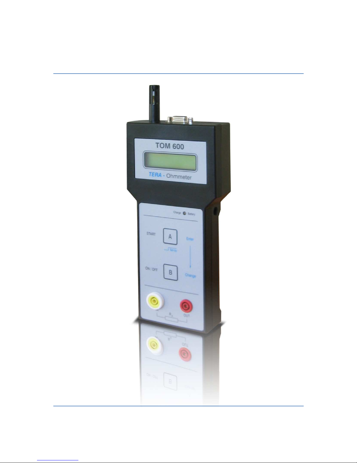
TERA Ohmmeter TOM 600
With integrated temperature and humidity sensor
Page 2

2 Manual TOM 600
1. Product Description
Due to its compact design and battery powered operation the TOM 600 is suited for mobile
applications in industrial areas. Furthermore it can be driven stationary with the provided wall
power supply.
The menu-driven TOM 600 is operated by only 2 push-buttons and therefore very user-friendly.
All set measurement parameters are shown in the display for a better orientation. Die provided
PC software enables you to perform computer driven measurements. In addition the
measurement data can be administrated and processed.
The TOM 600 works according to the voltage current measurement principle. The measurement
time required by norms, like DIN EN 61340 or EOS-ESD 4.1/6.1, can be set with an internal
timer.
While measuring in TIMER=ON mode data, including environment parameters, is stored in the
internal EEPROM memory. Thereby the data is maintained and can be read out later via the
serial PC port.
As resistance values of some materials depend on air humidity and temperature, these
environment parameters are measured and saved together with each measurement value. Thus
reproducible measurements can be performed.
1.1. Specifications
Dimensions (L x W x H): 224mm x 81mm x 40mm
Weight: 350g
Display: Alpha-numerical display, 2 lines with 16 digits each,
size: 60 mm x 25 mm
Ranges:
Resistance: 20 kΩ - 2.0 TΩ accuracy ± 1xEXX Ω
Temperature: 0°C....60°C accuracy ± 3°C
Rel. Humidity: 10%...90%r.F. accuracy ± 5%
PC interface: Serial interface, internal COM – USB Adaptor
PC software: KL_ReadOut Software
Battery: 4 x AA-NiMH 2100 mAh
Operation time with fully charged battery: > 12 hours
permanent operation
Charging time with provided wall power supply: max. 14h
Power supply: 9V-DC / 300 mA
Page 3
3
1.2. Legend
A
B
T
O
M
6
0
0
T
E
R
A
-
O
h
m
m
e
t
e
r
I
N
U
m
e
s
s
O
N
/
O
F
F
S
T
A
R
T
E
n
t
e
r
C
h
a
n
g
e
S
e
t
-
U
p
C
h
a
r
g
e
B
a
t
t
e
r
y
1
3
2
6
8
7
10
9
5
4
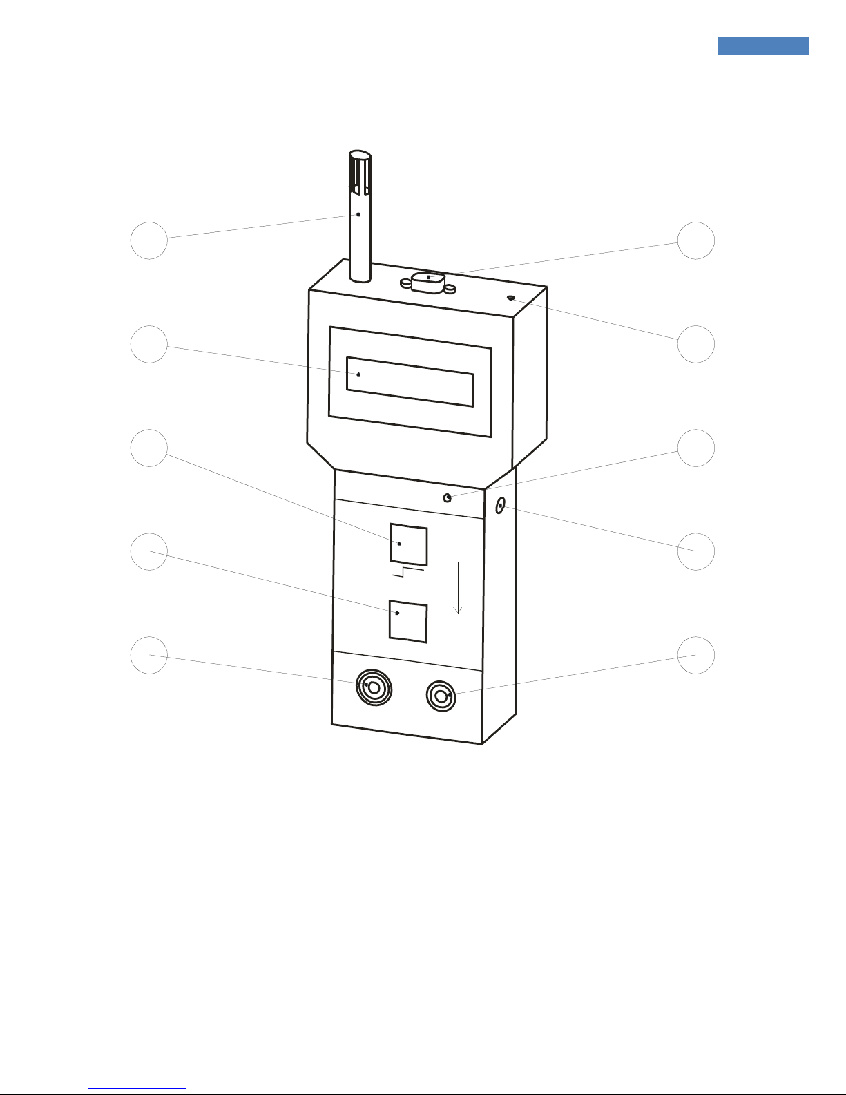
1 Temperature and humidity sensor 6 USB interface
2 LCD display 7 Display contrast trimmer
3 Button A 8 Battery charge indicator
4 Button B 9 Power supply connector
5 Measurement input 10 Measurement voltage output
Page 4

4 Manual TOM 600
2. Manual
2.1. Initiation
The TERA ohmmeter TOM 600 is shipped with 4 AA batteries and is therefore plug-and-play. For
charging the batteries only the provided wall power supply may be used.
For measuring the electrodes have to be connected to the appropriate connectors (q.v. legend)
and positioned on the object to measure. Afterwards button «B» has to be pressed to power the
device on.
Please pay attention moving on measurement lines and passing people as they can cause
electrostatic induction at the measurement input.
After powering on the software version is displayed::
In case of set measurement time the device prompts to press button «B». Afterwards the current
resistance value and the timer settings are displayed. If the timer is not set, the device
immediately returns:
Press button «B» to power the device off. In battery mode the device powers off automatically
after 5 minutes when no button was pressed.
2.2. Charging the NiMH Battery
The provided wall power supply has to be used to charge the batteries or operate the TOM 600.
For this the jack (9) must be connected to the power supply. If the charging works properly the
green indicator LED (8) is lit. The charging time for the provided batteries is max. 14h. Longer
charging has to be avoided as batteries can be overcharged and damaged.
The TOM 600 can be operated up to 12 hours with fully charged batteries.
R>2.0xE12ΩΩΩΩ
1
T=OFF2
Air: xx°C xx%r.F
TOM 600 V3.1
(c)KL/ 09
.2004
Page 5
5 Setup
2.3. Range Selection and Measurement Voltage
The TOM 600 provides a automatic range selection over the entire measurement range. The
device selects the measurement range according to the connected resistance.
Measurement range Measurement voltage
≤ 200kΩ: 10V DC
> 200kΩ: 100V DC
The automatic range selection can be turned off in the setup. A fixed measurement voltage can
be set. The available options are:
Measurement voltage Measurement range
10V 20kΩ … 200GΩ
100V 200kΩ … 2TΩ
3. Setup
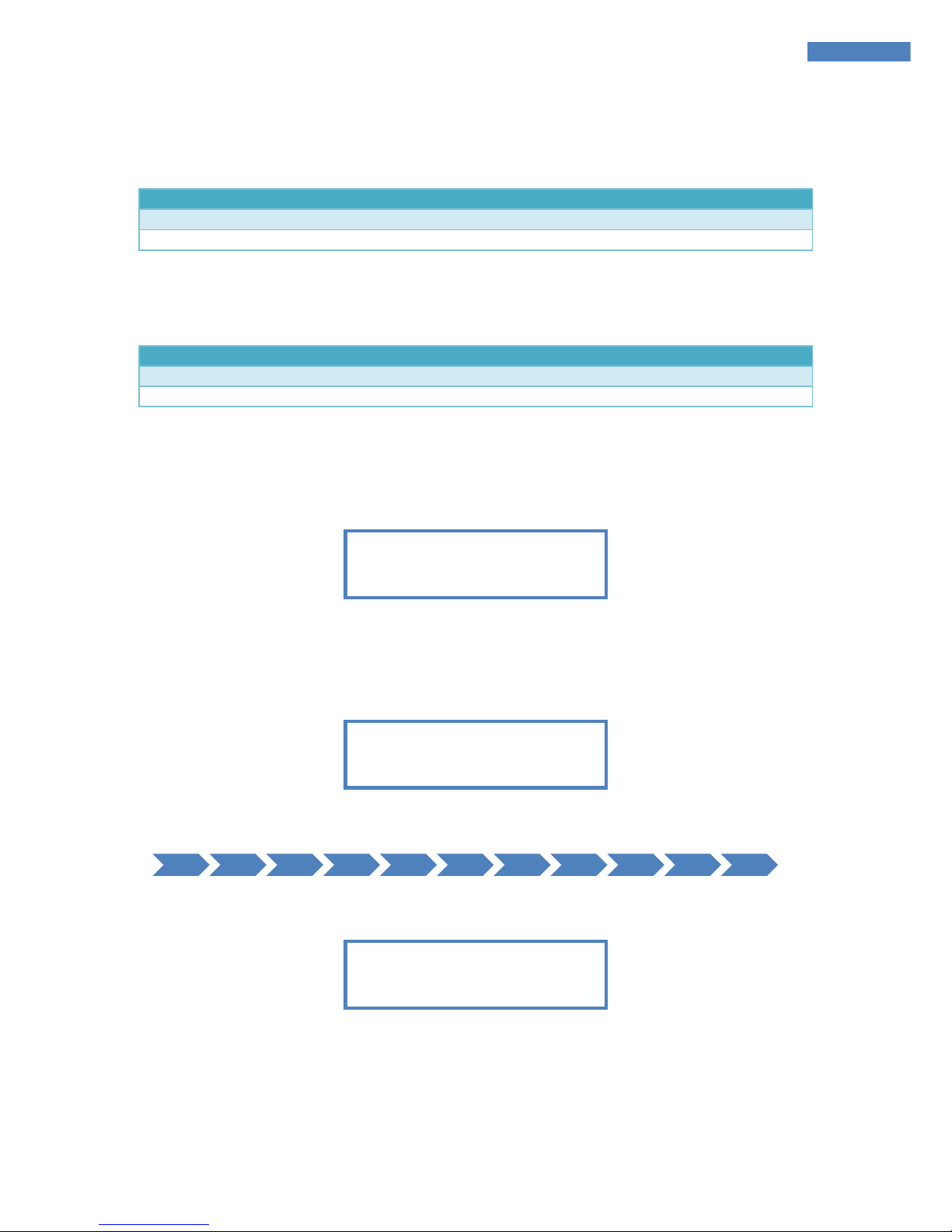
By pressing button «A» for about 2 seconds the setup menu is loaded. The device displays:
By pressing button «B» (Change) the timer can be switched on and off. If button «A» is pressed
while the display indicates OFF, the timer is turned off. Read on at section 3.1. If button «A» is
pressed while the display indicates ON, the measurement time can be set up next and the device
displays:
By pressing button «B» the measurement time is changed as follows:
Press button «A» to confirm the measurement time shown in the display. The device returns:
The measurement mode can switched between the average over the whole measurement time
(AVERAGE) or the last value at the end of the measurement (LAPSE) by pressing button «B».
The displayed mode can be confirmed with button «A».
1s 2s ... 10s 15s ... 60s 120s ... 240s 1s
TIMER MODE:
AVERAGE/LAPSE
NEW TIMER !
TIME = 001s
SET TIMER !
TIMER ON/OFF
Page 6
6 Manual TOM 600
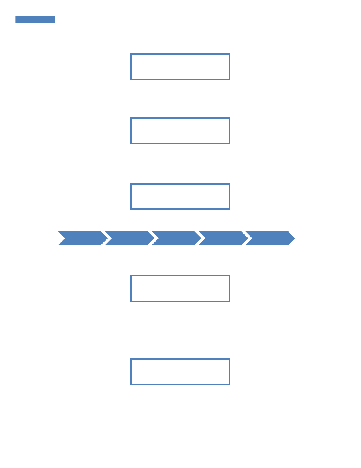
Afterwards the device prompts whether the data stored in the EEPROM (files) should be deleted:
Pressing button «B» switches between YES and NO. The selected action is confirmed by pressing
button «A». If all data is erased the saving will start on File No. 001 the next time. The display
returns:
3.1. Measurement Voltage / Display Mode
After finishing section 3 the measurement voltage and the display mode can be set up. First the
device prompts for the measurement voltage:
By multiply pressing button «B» you can choose between the following options:
Press button «A» to confirm the displayed function. Afterwards the number representation is
prompted:
By pressing button «B» you can switch between scientific and engineering representation. The
selection can be confirmed by pressing button «A».
If the timer is set off continue reading in section 3.2.
Afterwards the device is reset and returns in case of activated timer:
AUTO MAN. 10V MAN. 100V AUTO ...
T = XXXs R=Avg
AIR: xx°C xx%r.F
DISPLAY MODE
R>1.0xE12
Ω
VOLTAGE MODE
AUTO
FILES DELETED!
DEL FILES?
YES/NO
Page 7

7 Further Messages
The next measurement can be started by pressing button «A». The time T decrements in steps of
1s, by reaching 0 the measured resistance value is displayed with the amendment Avg for
AVERAGE or Lap for LAPSE. The second line shows the measured temperature and humidity
values, e.g:
Alternating with the temperature and humidity values the second line shows every 2s:
By pressing button «A» the measurement result, including temperature and humidity values,
can be saved using the displayed file number. Stored data can be read out via the PC interface
later.
3.2. Timer
In case of not activated timer the TOM 600 switches automatically to a live display of the
measured resistance value. The device returns e.g.:
4. Further Messages
In case of excessing the maximal measurement range, the device returns in the first line:
Scientific representation:
Engineering representation:
In case of undercutting the minimal measurement range, the device returns:
Scientific representation:
Engineering representation:
R<20(0)kΩ T=OFF
AIR: xx°C xx%r.F
R<2.0xE04(05)Ω T=OFF
AIR: xx°C xx%r.F
R>2.0TΩ(200GΩ) T=OFF
AIR: xx°C xx%r.F
R>2.0xE12(11)Ω T=OFF
AIR: xx°C xx%r.F
R=5.5xE10ΩΩΩΩ T=OFF
AUTO
AIR: xx°C xx%r.F
Avg=2.5xE9Ω
FN:XXX T=XXXs
Avg=2.5xE9Ω
AIR: xx°C xx%r.F
Page 8

8 Manual TOM 600
In case of changing resistance values the device searches the proper measurement range and
returns:
If the battery voltage undercuts 4,6 Volt, the display’s second line alternates with:
The battery has to be charged, though the current measurement can be completed. If the battery
voltage undercuts 4,3 Volt, the device powers automatically off to prevent battery drain after
displaying:
4.1. Adjust Display Contrast
On the device top side the display contrast can be adjusted with a tiny screw driver through a
small hole.
5. PC Operation
5.1. System Requirements
• Intel Pentium CPU or higher
• CD drive
• Free USB Port
• Microsoft Windows 95/98, 2000 or XP
• Microsoft Excel
5.2. Installation
see the the KL_ReadOut Manual
5.3. Starting the Software
Attach the TOM 600 by use of the provided cable to a USB Port and wait until Windows confirm
it. Then turn the device on. Double-click the corresponding desktop icon to start the KL_ReadOut
software.
BATTERY EMPTY!
AUTO SWITCH OFF!
LOW BATTERY!
WAIT!
Page 9

9 Maintenance / Calibration
6. Maintenance / Calibration
The device is maintenance-free. If the device is contaminated it can be cleaned by using a nonfuzzing cotton cloth and solvent-free cleanser. The device must not be opened On opening the
device warranty is void. If the device is not used for longer terms batteries should be removed.
Always store batteries charged.
The recommended factory calibration interval is 1 year.
7. Warranty
In case of proper use we issue warranty within 24 month after shipping. Mechanical damage and
the batteries are exempted from the warranty. Warranty is void on opening the device.
8. Scope of Delivery
TOM 600
• TERA ohmmeter TOM600 with
temperature and humidity sensor
• 4 x. NiMH batteries (AA)
• Conductive carrying case
with foam insert
• Wall power supply 9V-DC / 500mA
• 2 x teflonized measurement line (1m )
• PC cable 9 pol.
• CD with PC software and manual
• Manual
• Declaration of factory calibration
TOM 600 ME
Same as TOM 600, but:
• 1 x. teflonized measurement line (5m)
instead of 1 x teflonized.measurement
line (1m )
• Pair of 2,50 kg electrodes according to
EOS/ESD S 4.1/S 7.1 and
DIN EN 61340 –5-1, -4-1, -2-3
for the measurement of grounding
bleeder resistances and point to point
measurements, especially for conductive
table and floor coverings
9. Security Advices
The TOM 600 is not approved for measurements in explosive areas. Operation in power plants is
not permitted.
Notice: Please make sure the object to be measured is potential free before every measurement.
External voltage can distort the measurement results and damage the instrument.
The device must not be operated without rechargeable batteries!
Page 10
10 Manual TOM 600
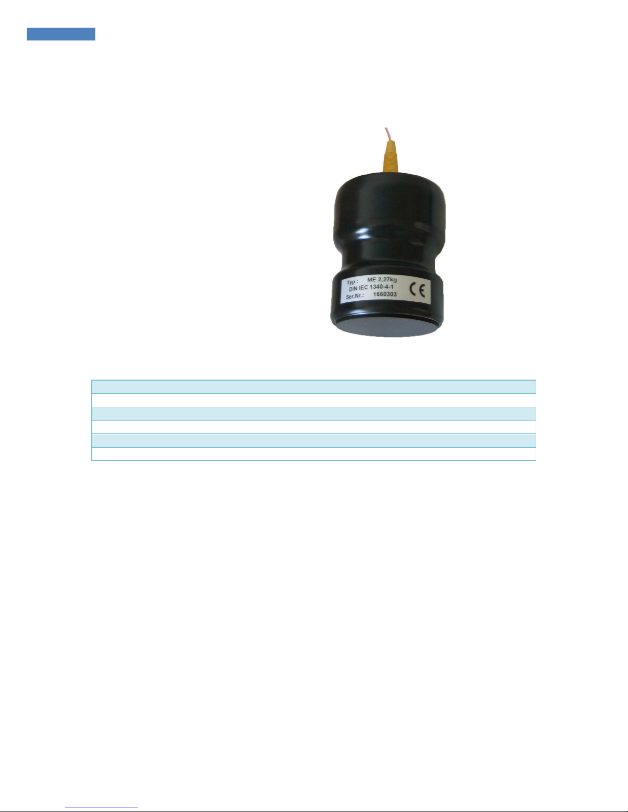
10. Measuring Electrodes ME 250
The 2.5kg electrodes enable measurements of surface and bleeder resistances on table or floor
coverings according to the following norms:
• EOS / ESD – S 4.1 /S 7.1
• EN 100015 Teil1, IEC 93
• IEC 61340-5-1
• DIN IEC 1340-4-1
10.1. Specifications
Dimensions (L x W x H): Diameter 70mm, height 100mm
Contact rubber: Diameter: 63mm, Shore hardness: 60
Weight: 2,5kg
Connection: Banana jack 4mm, topside centrical
Isolation: Shrink hose R>1011Ω (U=100V)
Contact resistance: <1kΩ (measured on a metal plate, U=10V)
10.2. Important Information
Please consider the following advices for reproducible results:
• The contact surface of the measurement electrodes must be kept clean to ensure a
optimal contact resistance
• The covering to measure should also be cleaned
• Measurements may only be performed in zero-potential condition
• The measurement line should be as short as possible but as long as necessary
• For the measurement of high resistances teflonized measurement lines are inevitable
• For repetitious accuracy in high resistance ranges holding time or a timer function
should be considered
• To avoid influences of electrostatic induction cables must not be moved during the
measurement
• The conductivity of some materials depends on temperature and humidity, therefore
these values need to be logged
• For adequate accuracy the corresponding norms should be complied with
Page 11
11 Measuring Techniques according to IEC 61340-4-1
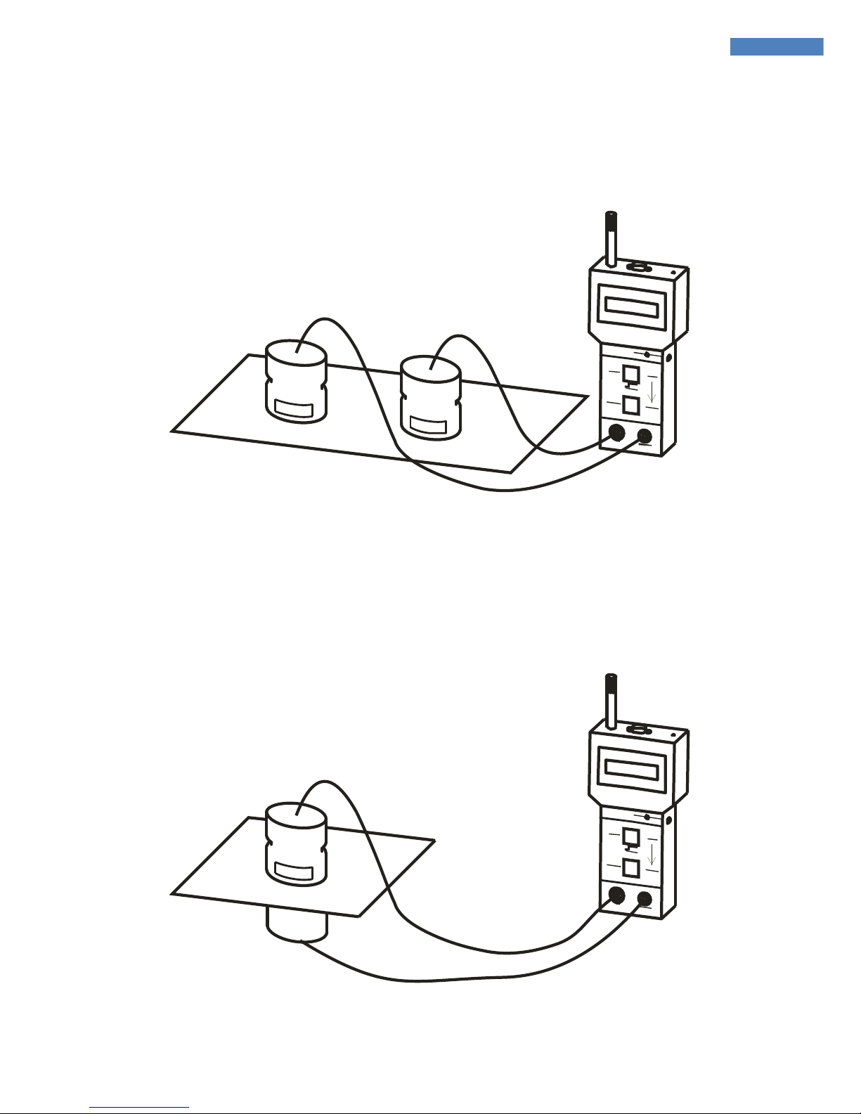
11. Measuring Techniques according to IEC 61340-4-1
11.1. Surface Resistance (point to point)
The electrodes have to be put on the covering to measure. The measured resistance depends on
the conductivity, the surface condition and the distance between the electrodes.
A
B
T
O
M
6
0
0
T
E
R
A
-
O
h
m
m
ete
r
11.2. Volume Resistance
The covering has to be put between a metal plate and one electrode or between both electrodes.
The measured resistance depends on the conductivity, the material thickness and the surface
condition.
A
B
T
O
M
6
0
0
T
E
R
A
-
O
h
m
m
ete
r
Page 12
12 Manual TOM 600
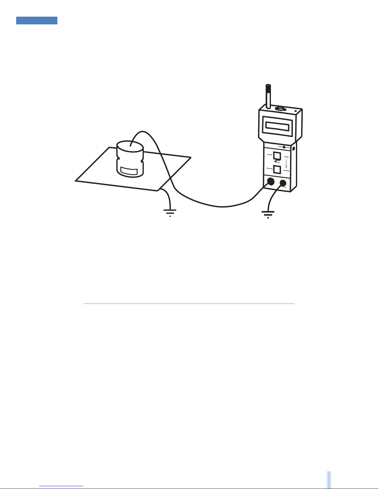
11.3. Leakage Resistance (point to ground)
The resistance of a covering to ground potential is measured. The measured resistance depends
on the material’s conductivity, its surface condition, the electrodes distance to the grounding
point and the quality of the grounding.
A
B
T
O
M
6
0
0
T
E
R
A
-
O
h
m
m
e
t
e
r
Furthermore a ring measurement electrode for measurements
according to DIN EN 61340-2-3 is available as accessory.
©20
12 Kleinwächter GmbH
 Loading...