

Page 1
1. DECLARATION OF CONFORMITY
declares that the machines descripted in this manual must be use
solely for professional purposes in an industrial environment and they
are manufactured in compliance with the instructions contained in
the harmonized standard:
2006/95/CE (LDV) – 2004/108/CE (EMC) – 2002/95 (RoHs)
and with the instructions contained in the harmonized standard,
if applicable:
EN 60974-1 EN 60974-2 EN 60974-3 EN 60974-5 EN 60974-7
EN 60974-10 EN 60974-12
Date 31/01/2012 Maurizio Terzo
General Manager
The equipment don’t compiles with EN/ IEC 61000-3-12.
The installer or the user must be sure that it can be connected to the public low voltage power line,
if necessary, in consultation with the network distributor.
OPERATING MANUAL
Inglese
GB
GB
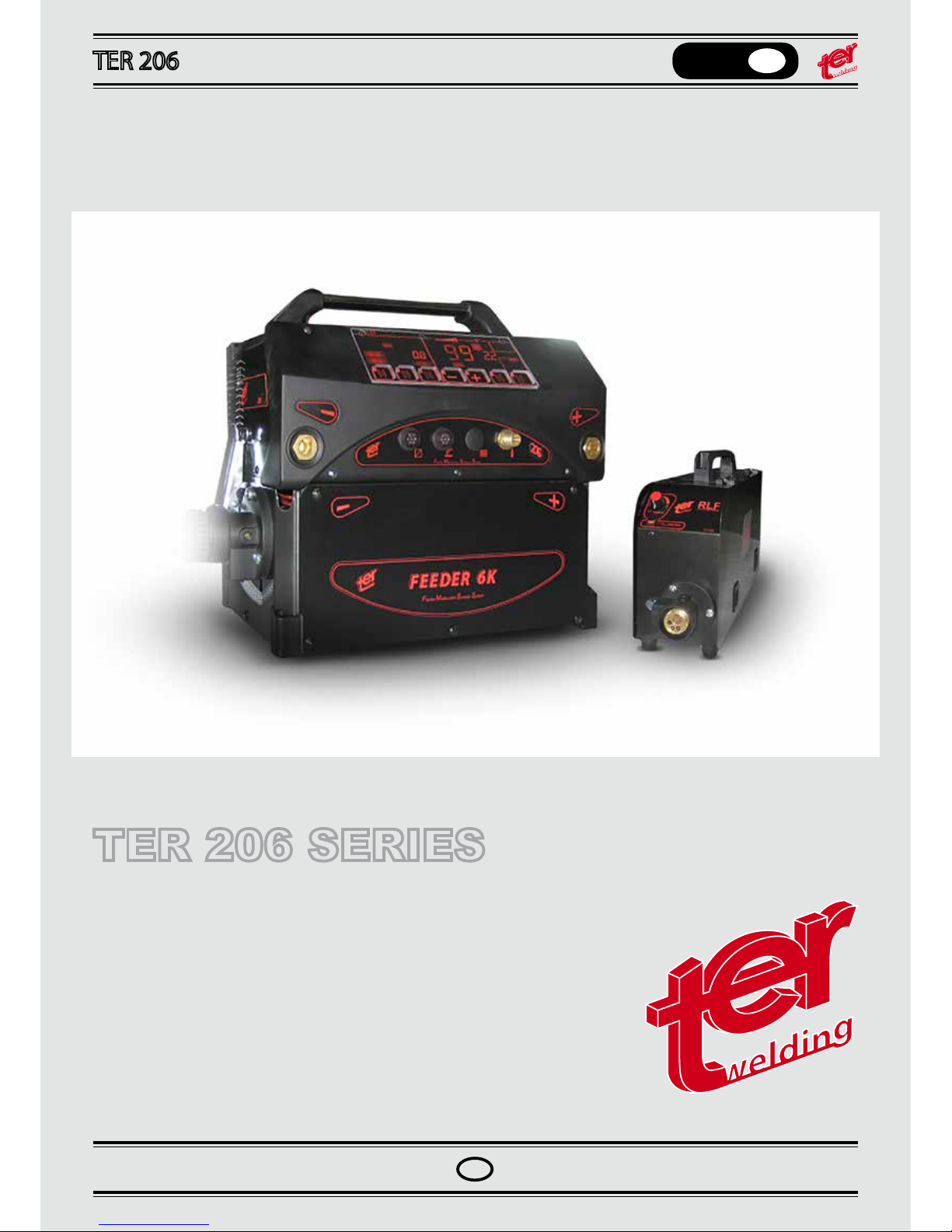
TER 206 SERIES
This manual must be completed by the “CE Operating and service maual” Edition of 29/07/2015 Rev.00
Page 2

Page 3

OPERATING MANUAL
English
GB
GB
1. DECLARATION OF CONFORMITY
TER SRL - Via Leopardi, 13 - 36030 Caldogno (VI) Italy
declares that the machines descripted in this manual must be use
solely for professional purposes in an industrial environment and they
are manufactured in compliance with the instructions contained in
the harmonized standard:
2006/95/CE (LDV) – 2004/108/CE (EMC) – 2002/95 (RoHs)
and with the instructions contained in the harmonized standard,
if applicable:
EN 60974-1 EN 60974-2 EN 60974-3 EN 60974-5 EN 60974-7
EN 60974-10 EN 60974-12
Date 31/01/2012 Maurizio Terzo
General Manager
IN CASE OF BAD OPERATION YOU DEMAND
THE
ATTENDANCE OF QUALIFIED STAFF
The equipment don’t compiles with EN/ IEC 61000-3-12.
The installer or the user must be sure that it can be connected to the public low voltage power line,
if necessary, in consultation with the network distributor.
Page 4
OPERATING MANUAL
English
GB
GB
WARNING
IMPORTANT: BEFORE STARTING THE EQUIPMENT, READ THE CONTENTS OF THIS MANUAL, WHICH MUST
BE STORED IN A PLACE FAMILIAR TO ALL USERS FOR THE ENTIRE OPERATIVE LIFE-SPAN OF THE MACHINE.THIS EQUIPMENT MUST BE USED SOLELY FOR WELDING OPERATIONS.
1. Conformity declaration
The machines descripted in this manual, TER 166/186, must be used solely for professional purposes in an industrial
environment and they are manufactured in compliance with the instructions contained in the harmonized standard
EN50199 (electromagnetic compatibility) and EN60974-1.
IN CASE OF BAD OPERATION YOU DEMAND THE ATTENDANCE OF QUALIFIED STAFF.
1.1 RAEE Norm
The symbol on the product or on its packaging indicates that this product may not be treated as household waste.
Instead it shall be handed over to the applicable collection point for the recycling of electrical and electronic equipment. By ensuring this product is disposed of correctly, you will help prevent potential negative consequences for the
environment and human health, which could otherwise be caused by inappropiate waste handling of this product. For
more detailed information about recycling of this product, please contact your local city ofce, your household waste
disposal service or the shop where you purchased the product.
2. SAFETY PRECAUTIONS
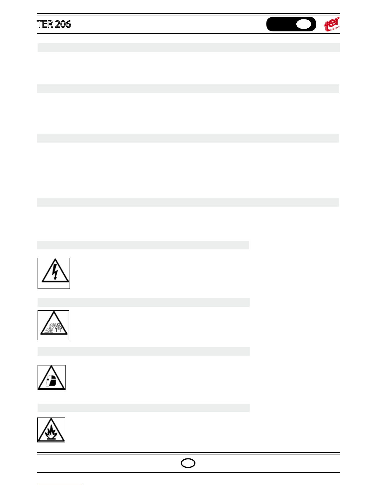
WELDING AND ARC CUTTING CAN BE HARMFUL TO YOURSELF AND OTHERS. The user must therefore be educated against the hazards, summarized below, deriving from welding operations.
ELECTRIC SHOCK – May be fatal.
Install and earth the welding machine according to the applicable regulations.
Do not touch live electrical parts or eletrodes with bare skin, gloves or wet clothing.
Isolate yourselves from both the earth and the workpiece.
Make sure your working position is safe.
FUME AND GASES – May be hazardous to your health.
Keep your head away from fumes.
Work in the presence of adequate ventilation, and use ventilators around the arc to prevent gases from
forming in the work area.
ARC RAYS – May injure the eyes and burn the skin.
Protect yuor eyes with welding masks tted with ltered lenses, and protect your body with appropiate
safety garments.
Protect others by installing adequate shields or curtains.
RISK OF FIRE AND BURNS
Sparks (sprays) may cause res and burn the skin; you should therefore make sure there are no
ammable materials in the area, and wear appropriate protective garments.
NOISE
PACEMAKERS
EXPLOSIONS
3. General description
This machine is a constant direct current power source, designed for welding electrically conductive materials (metals
and alloys) using the electical arc procedure.
Page 5
OPERATING MANUAL
English
GB
GB
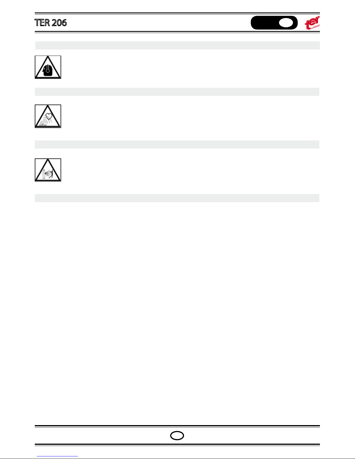
NOISE
This machine does not directly produce noise exceeding 80dB. The plasma cutting/welding procedure
may produce noise levels beyond said limit; users must therefore implement all precautions required by
law.
PACEMAKERS
The magnetic elds created by high currents may affect the operation of pacemakers. Wearers of vital
electronic equipment (pacemakers) should consult their physician before beginning any arc welding,
cutting, gouging or spot welding operations.
EXPLOSIONS
Do not weld in the vicinity of containers under pressure, or in the presence of explosive dust, gases or
fumes. All cylinders and pressure regulators used in welding operation should be handled with care.
3. General description
This machine is a constant direct current power source, designed for welding electrically conductive materials (metals
and alloys) using the electical arc procedure.
Page 6
OPERATING MANUAL
English
GB
GB
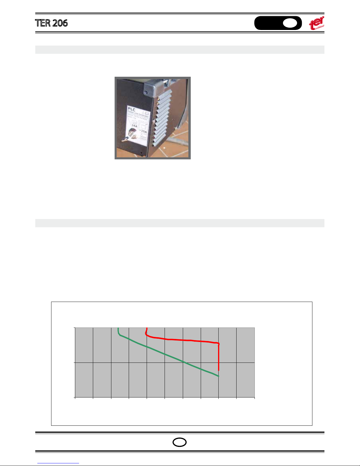
PLC - Power Line Controller
The machine with PLC has a key socket in the back panel.
Held one copy of the key in a safe place (if both the key are lost, the complete key block must be replaced).
The domestic (inside houses) power supply
is limited at 16A; to use the machine in that
condition, t set the key on 16A position.
Use the key to select the power supply
range.
Note: The plug used in the supply cable of the machine must be an industrial plug ≧25A, when the machine is
used at maximum power. The PLC key must be positioned on 25 A (industrial applications).
Don’t use the 16A plug for industrial applications.
The key must be removed from the machine after the power supply setting.
PLC FUNCTION
The Ter 166 and Ter 186 series are industrial power sources for light/medium applications; the duty cycle is very
high and the design of the power inverter allows hight current rates. When the machines are connected to the
domestic (house) power supply a plug 16A should be mounted; the input current must be less than average 16A in
order to avoid the switching-o of the main switch protecting the power line.
The PLC feature controls the input current, automatically inhibiting the welding process when the power input rise
the limit of the main line switch (16A).
The power of the machine isn’t reduced, only the welding time (duty cycle) is concerned when the current is
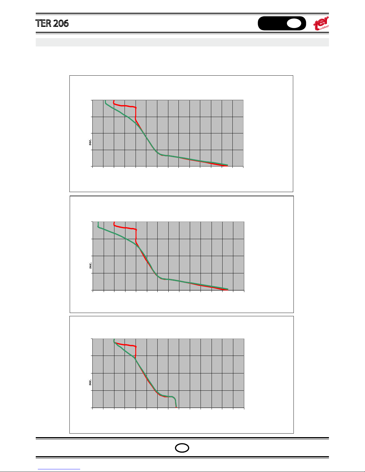
highter than the available one from net, as shown in the picture below, where we compare the available welding
time in function of the welding current between industrial (red plot) and domestic (green plot) for a mig setting.
LIMITATION OF THE WELDING TIME WITH PLC
10
100
1000
100 110 120 130 140 150 160 170 180 190 200
CURRENT
sec.
PLC curves
The following three curves shown the reduced data for the applications of the machine in MMA, Mig and Tig.
The red plots are for industrial applications and the green ones are for domestic with the PLC key turned in 16A
position.
MIG PULS MIG PLC
0,1
1
10
100
1000
100 120 140 160 180 200 220 240 260 280 300 320 340 360 380
CURRENT
ELCTRODE PLC
0,1
1
10
100
1000
100 120 140 160 180 200 220 240 260 280 300 320 340 360 380
CURRENT
TIG TIG PULSE PLC
0,1
1
10
100
1000
100 120 140 160 180 200 220 240 260 280 300 320 340 360 380
CURRENT
Page 7
OPERATING MANUAL
English
GB
GB
PLC curves
The following three curves shown the reduced data for the applications of the machine in MMA, Mig and Tig.
The red plots are for industrial applications and the green ones are for domestic with the PLC key turned in 16A
position.
MIG PULS MIG PLC
0,1
1
10
100
1000
100 120 140 160 180 200 220 240 260 280 300 320 340 360 380
CURRENT
ELCTRODE PLC
0,1
1
10
100
1000
100 120 140 160 180 200 220 240 260 280 300 320 340 360 380
CURRENT
TIG TIG PULSE PLC
0,1
1
10
100
1000
100 120 140 160 180 200 220 240 260 280 300 320 340 360 380
CURRENT
Page 8

OPERATING MANUAL
English
GB
GB
PLC signals
When the PLC inhibit the welding, the current supply is breaked immediately, and the front panel shows the PLC
timer count down.
When the timer arrive to 0, the welding can restart.
Please refer to the plots in order to avoid unexpected welding interruptions when the machine is used on domestic lines.
VRD - Voltage Reduction Device
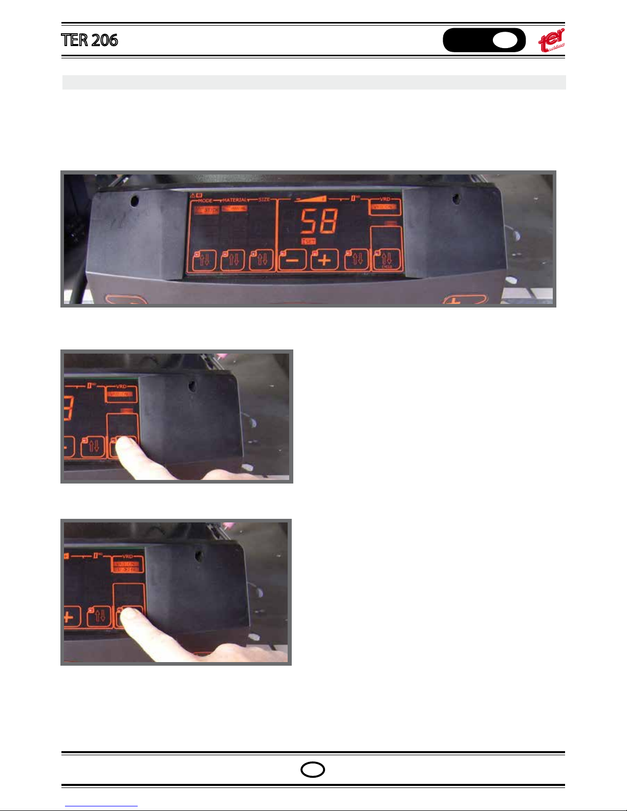
IThis function reduces the output no load voltage at a value less than 25V in a very short time.
It increases the safety conditions of the machine user: the no load voltage is not dangerous but contact trough
human body and live parts of earth cable and electrode holder can cause a shock with lost of equilibrium control
or similar.
The simbol “VRD” lighting on means that VRD protection is active with an output no load voltage equal to 15V.
When “VRD” feature is o, an icon led shows voltage greather than 25V.
The machine stops its main functions when it is not continuosly used, in order to reduce the power consumption
at 10W, and “STANDBY” icon lights.
The fan works only when the machine need to be cooled down; during ligth applications, the fan normally doesn’t work
Page 9
OPERATING MANUAL
English
GB
GB
VRD - Voltage Reduction Device
IThis function reduces the output no load voltage at a value less than 25V in a very short time.
It increases the safety conditions of the machine user: the no load voltage is not dangerous but contact trough
human body and live parts of earth cable and electrode holder can cause a shock with lost of equilibrium control
or similar.
The simbol “VRD” lighting on means that VRD protection is active with an output no load voltage equal to 15V.
When “VRD” feature is o, an icon led shows voltage greather than 25V.
Setting:
when VRD is o, press the “CYCLE” pushbutton for 7
seconds; once the “VRD” led start ashing release the
button pressure.
when VRD is on, press the “CYCLE” pushbutton for 7 seconds until the VRD icon ligth o.
In the meantime the icon U2>25LV should light on.
The machine stops its main functions when it is not continuosly used, in order to reduce the power consumption
at 10W, and “STANDBY” icon lights.
The fan works only when the machine need to be cooled down; during ligth applications, the fan normally doesn’t work
.
Page 10
OPERATING MANUAL
English
GB
GB
The machine stops its main functions when it is not continuosly used, in order to
reduce the power consumption at 10W, and “STANDBY” icon lights.
The fan works only when the machine need to be cooled down; during ligth
applications, the fan normally doesn’t work.
Power supply control
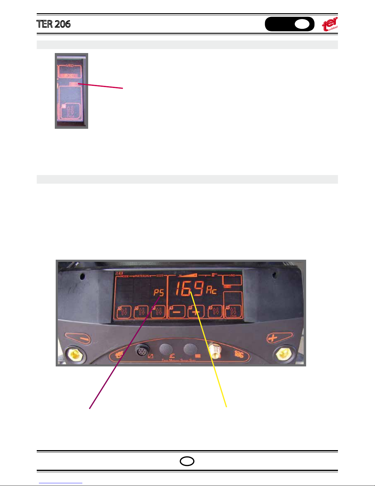
The machine can be used with motogenerator power supply and/or long supply cables; the supply voltage should
run between 180V and 270V limits.
When the supply voltage overlaps those limits, the machine functions stop and the main panel lights the last supply voltage, like picture shows.
Functions can be recovered switching the machine o and than on again.
STAND BY
Means “Power Supply ” 169V was the voltage before the
machine shut down
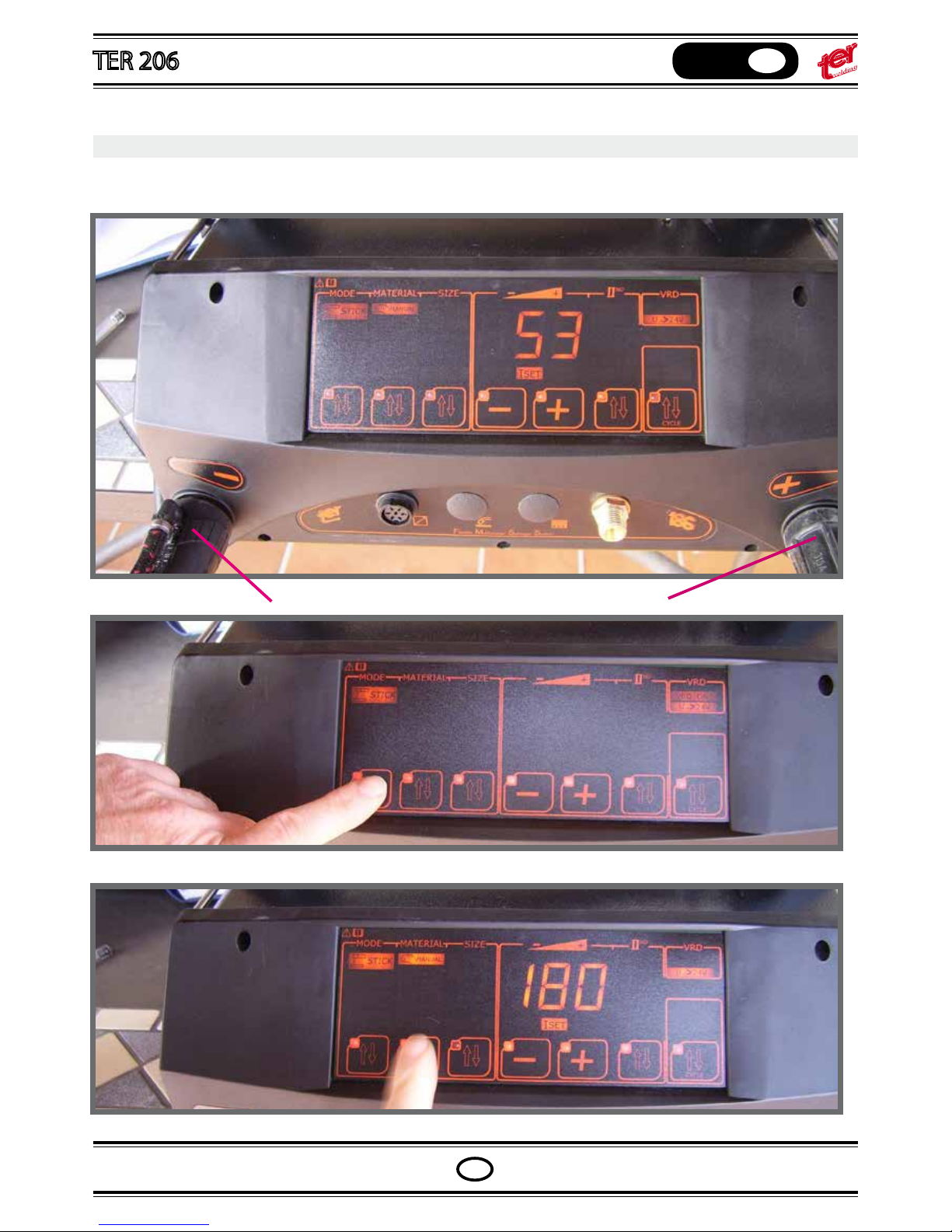
MMA WELDING: MANUAL MODE SETTING
Connect the electrode holder and the earth clamp plugs to the correct machine polarities, according to the
electrode manufacturer specs.
Press the rst pushbutton and select the icon “STICK”
Press the second pushbutton and select icon “MANUAL”
Page 11
OPERATING MANUAL
English
GB
GB
MMA WELDING: MANUAL MODE SETTING
Connect the electrode holder and the earth clamp plugs to the correct machine polarities, according to the
electrode manufacturer specs.
Negative polarity
Positive polarity
Press the rst pushbutton and select the icon “STICK”
Press the second pushbutton and select icon “MANUAL”
Page 12
OPERATING MANUAL
English
GB
GB
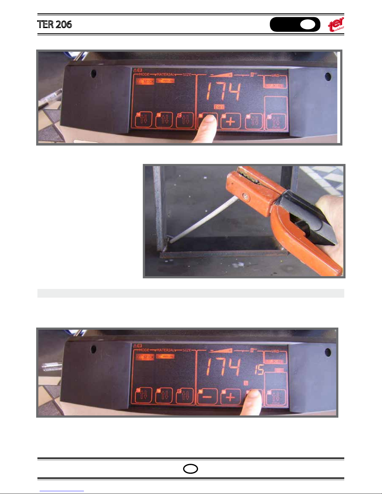
Set with pushbuttons “+” or “-” the required welding current
start the welding
THE DYNAMIC OF THE ARC
It can be changed according to the electrode type.
Example: stainless steel and rutil electrodes must have a “soft dynamic” (close to 0), basic and the majority of the
industrial electrode applications need a “medium dynamic” (10-12), while cellulosic needs a high one.
Setting:
Press the second level pushbutton: the icon “HS” lights and its value appears on the display.
The icon ash for two seconds and durig this time, pressing the pushbuttons “+” and “-” adjust the value.
Two seconds after the last touching the display sort out from setting mode.
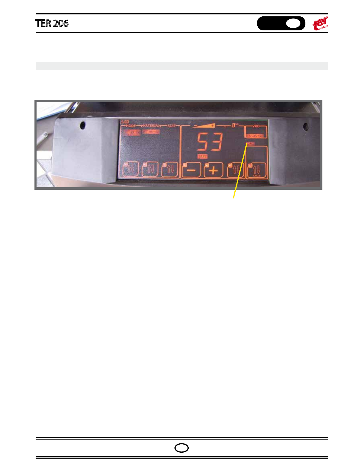
ANTI-STICKING
During the MMA welding process, the electrode may stick on the workpiece; thanks to the anti-sticking feature the
current is inhibited until the electrode unstick.
Once active, the “Antisticking” icon ash on the front panel.
Any setting in the MMA (stick) manual mode, once xed, is considered like a user program; it means once the user
select the stick manual mode again, the last adjustment is recovered and proposed.
Again, if the machine is turned o, for any reason, the last mode and setting are proposed in the front panel.
Page 13
OPERATING MANUAL
English
GB
GB
ANTI-STICKING
During the MMA welding process, the electrode may stick on the workpiece; thanks to the anti-sticking feature the
current is inhibited until the electrode unstick.
Once active, the “Antisticking” icon ash on the front panel.
ANTISTICKING
Any setting in the MMA (stick) manual mode, once xed, is considered like a user program; it means once the user
select the stick manual mode again, the last adjustment is recovered and proposed.
Again, if the machine is turned o, for any reason, the last mode and setting are proposed in the front panel.
Page 14
OPERATING MANUAL
English
GB
GB
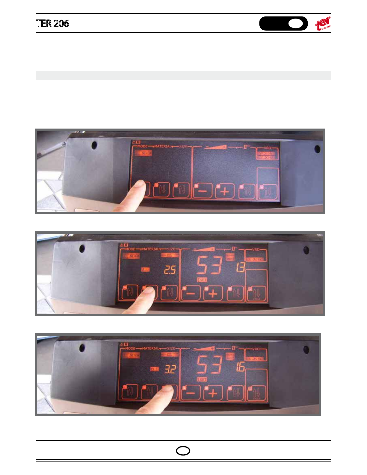
MMA WELDING: SYNERGIC MODE SETTING
MMA electrode synergic mode is an exclusive and powerfull solution to approach the MMA welding avoiding
setting mistakes.
Even professional welders can use the synergic mode in order to approach faster new settings.
Press the rst pushbutton and select the icon “STICK”
Press the second pushbutton and select the material type
With the third pushbutton select the electrode diameter
Set with pushbuttons “+” or “-” the required wel-
ding current or workpiece tickness
NOTE:
The workpiece thickness is based over a standard orizontal welding.
In case of dierent joints or positions, increase or decrease the current/thickness values.
ARC DYNAMIC
It is already set with an optimal value according to the choosed basic material and electrode but it can be adju-
sted as shown on chapter “The dynamic of the arc”.
The adjustment works in % value over the program setting
Once settings are given, they are stored as default programs for MMA synergic mode. The modied personalized
setting will be proposed as default program during the following stick synergic setting mode.
Page 15
OPERATING MANUAL
English
GB
GB
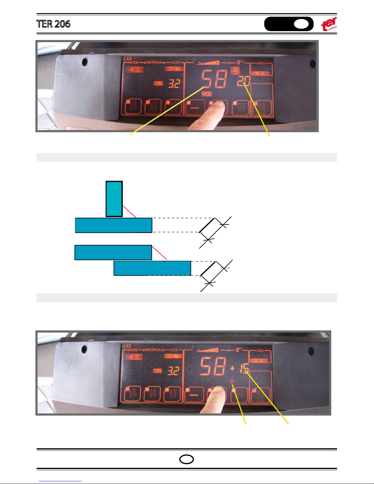
Set with pushbuttons “+” or “-” the required welding current or workpiece tickness
The workpiece thickness is shown and
helps the user with the current setting
NOTE:
The workpiece thickness is based over a standard orizontal welding.
In case of dierent joints or positions, increase or decrease the current/thickness values.
equivalent thickness
equivalent thickness
ARC DYNAMIC
It is already set with an optimal value according to the choosed basic material and electrode but it can be adjusted as shown on chapter “The dynamic of the arc”.
The adjustment works in % value over the program setting
Dynamic icon selected Increase dynamic by 15%
Once settings are given, they are stored as default programs for MMA synergic mode. The modied personalized
setting will be proposed as default program during the following stick synergic setting mode.
Page 16
OPERATING MANUAL
English
GB
GB
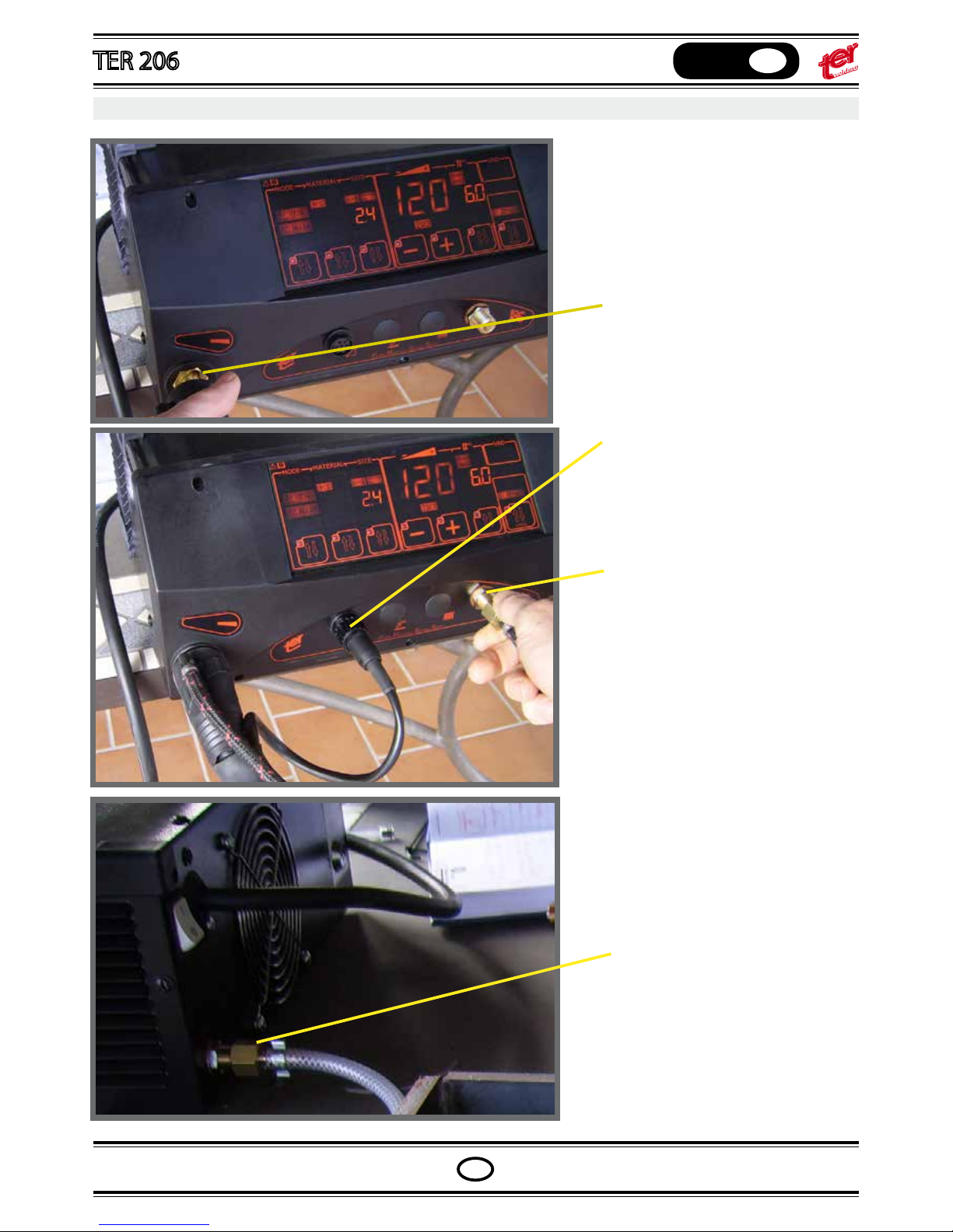
TIG WELDING – machine setting
Connect the tig torch to the negative
polarity
Connect the auxiliary plug (if the
machine is provided with the remote
control socket)
Connect the torch gas hose to the
output nipple (if the machine is
equipped with gas control)
Connect the argon gas bottle to
the input gas nipple located on the
machine back side and adjust the
gas ow between 5 to 7 liters per
minute
LIFT ARC MODE
Page 17
OPERATING MANUAL
English
GB
GB
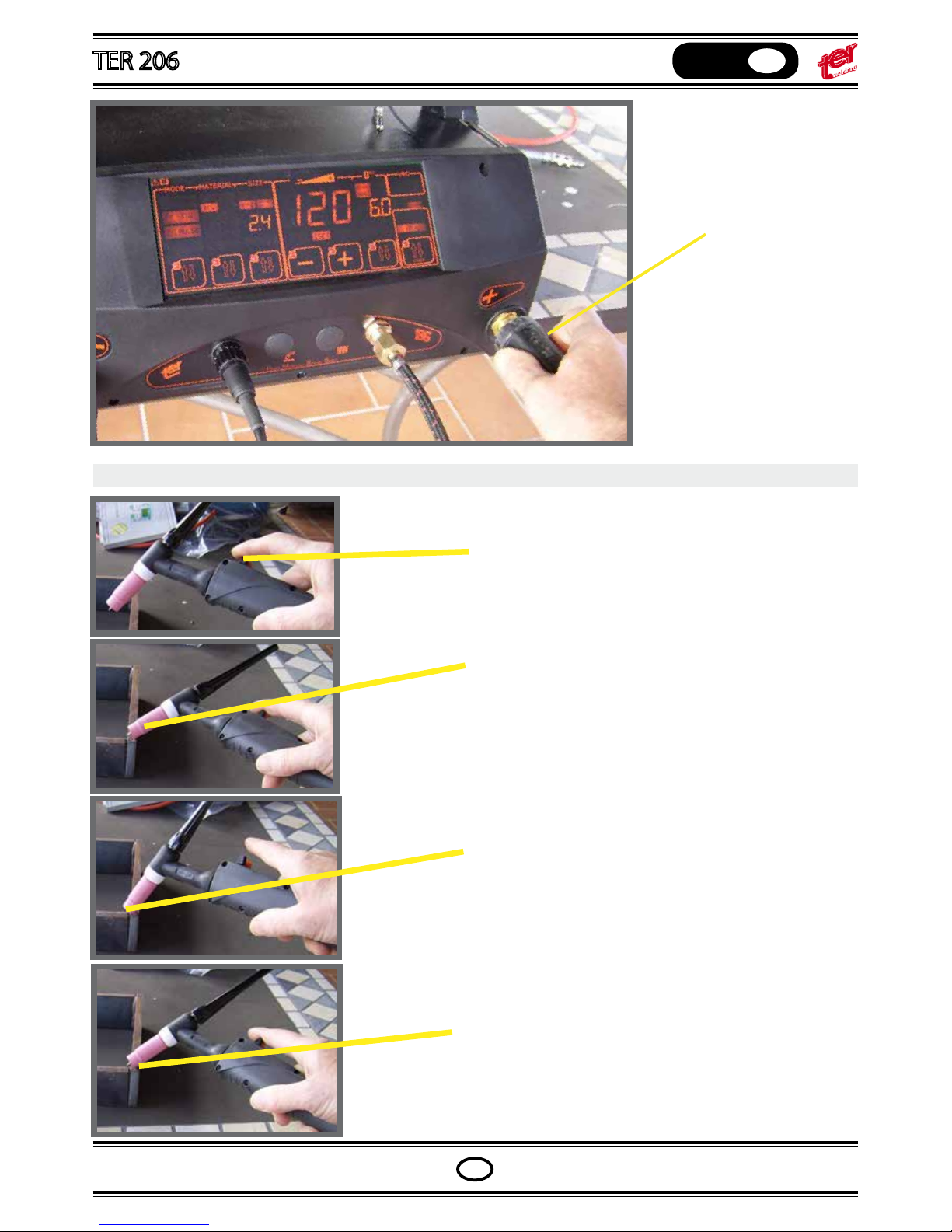
Connect the
workpiece earth
cable to the positive
polarity
LIFT ARC MODE
Push the torch switch. If the solenoid gas valve is not
controlled by the torch switch, open the gas ow.
Slow down the torch until the ceramic nozzle touch the
workpiece; in this phase held the torch and avoid any
contact between tungsten and workpiece.
Keeping the nozzle in contact, turn the torch until the
tungsten enters in contact with the workpiece
Maintaining the nozzle-work piece contact, turn back
the torch to the original position; the arc strikes and the
welding can be performed.
Page 18
OPERATING MANUAL
English
GB
GB
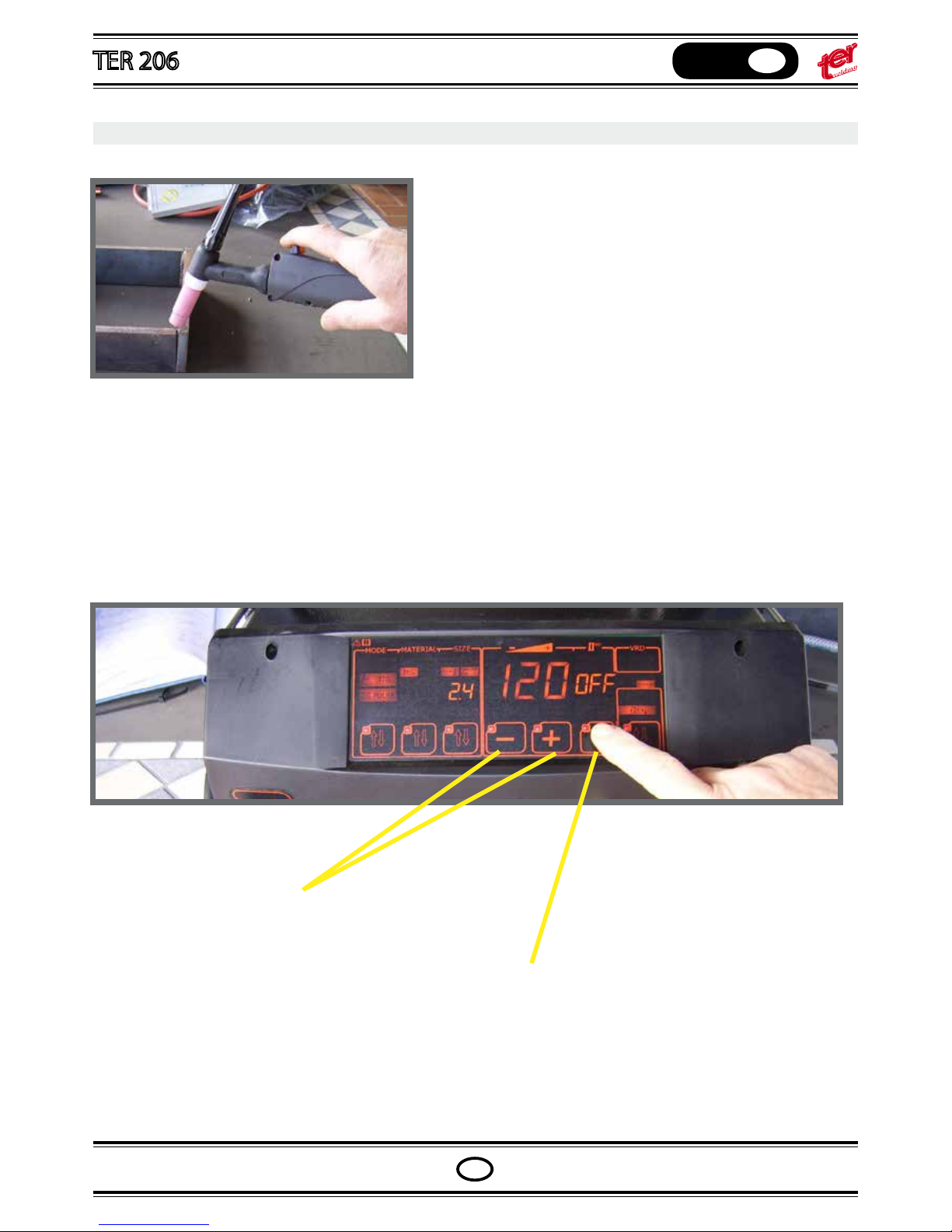
HIGH FREQUENCY MODE
Approach the work piece with the torch up to a dinstance of
3-5 mm. from tungsten.
Push the torch switch to strike the arc; if the arc doesn’t ignit,
the high frequency impulse stops after 4 seconds. Drive again
the torch switch.
In particular environment conditions such as hospitals, aerports, active nuclear plants, etc. the high frequency
should be forbitten.
In that case, deselect the high frequency and use only lift arc start.
Press “+” and “-” pushbuttons to select or
deselect the high frequency mode
Press the second level pushbutton up to
the icon “HF” ash
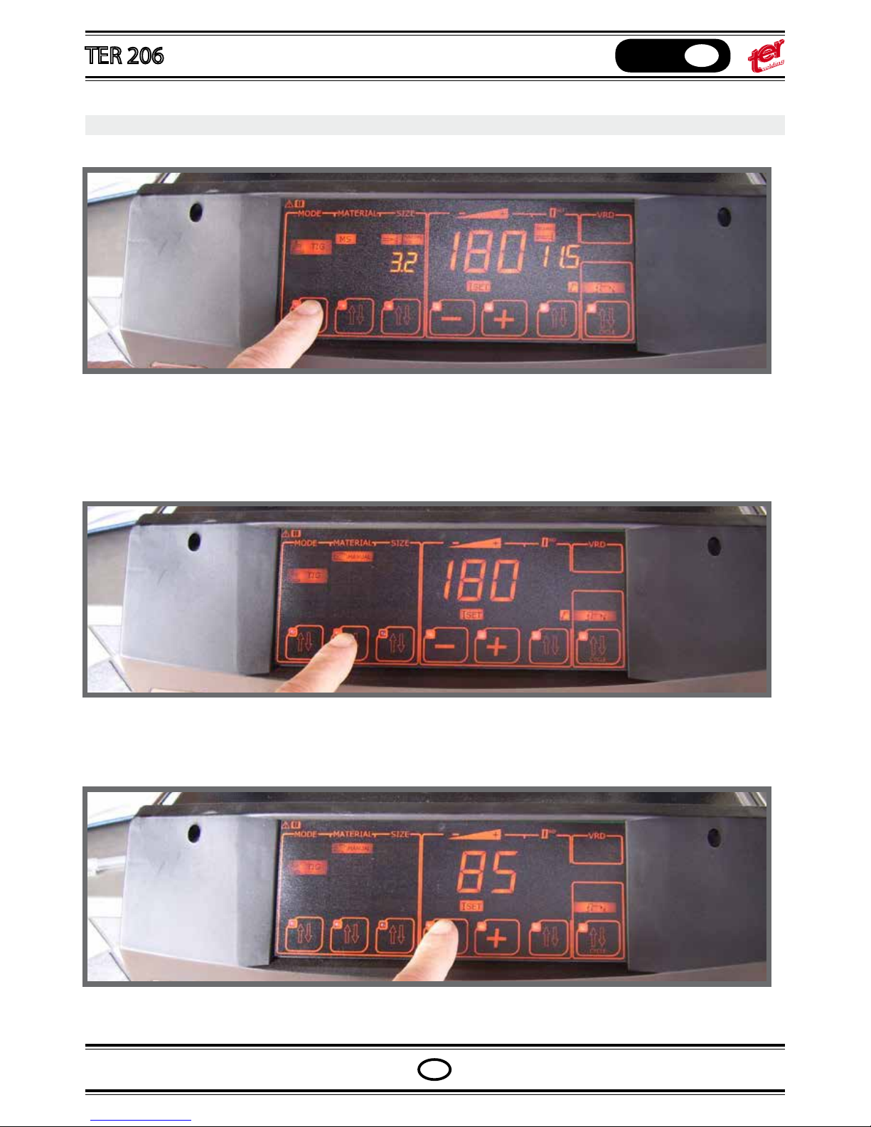
CURRENT SETTING – Manual
Press the rst pushbutton and select “TIG” or “TIG PULSE”
Press the second pushbutton and select “MANUAL”
With the third pushbutton select the electrode diameter
Set with pushbuttons “+” or “-” the required welding current
Page 19
OPERATING MANUAL
English
GB
GB
CURRENT SETTING – Manual
Press the rst pushbutton and select “TIG” or “TIG PULSE”
Press the second pushbutton and select “MANUAL”
With the third pushbutton select the electrode diameter
Set with pushbuttons “+” or “-” the required welding current
Page 20
OPERATING MANUAL
English
GB
GB
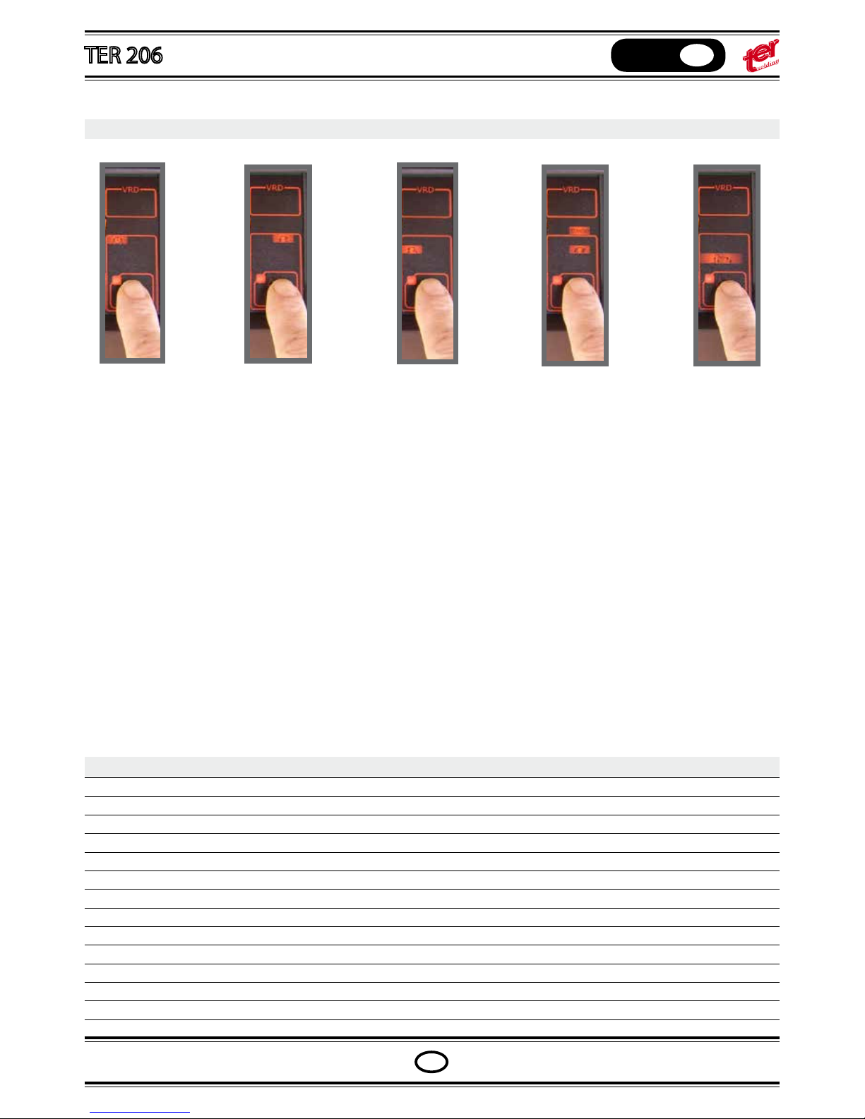
SWITCH CYCLES – Setting
TIMER
The current stops
after the set time;
can restart with a
new arc strike.
Available both
with lift and HF
arc strike mode
TWO STEPS
The current starts
when the torch
switch drives the
cycle and stops
when it is released. Up and down
slopes are not
allowed
TWO STEP
SLOPE
The current starts
when the torch
switch drives the
cycle and stops
with a down slope
when the torch
switch is released
FOUR
STEPS
The current starts
when the torch
switch drives the
cycle and stops
when the torch
switch is pressed
again
FOUR
STEPS SLOPE
The current starts
at level 1 at the
rst torch switch
pressure; slope
rise up releasing
the torch switch.
Down slope to
current I3 at
second switch
pressure and
stop with switch
release.
NOTES:
In manual tig setting certain parameters can be adjusted by the user while others are xed:
PREGAS x at 0,1 sec
UP slope automatic depending from down slope
CURRENT 1 (initial current) xed
CURRENT 3 (craterller nal current) xed
DOWN slope variable and synergic (select the icon with second level pushbutton)
POST GAS variable and synergic (select the icon with second level pushbutton)
PULSE FREQUENCYvariable and sinergyc (select the icon with second level pushbutton)
PULSE BALANCE variable and sinergyc (select the icon with second level pushbutton)
TIMER variable and sinergyc (select the icon with second level pushbutton)
PULSE PEAK automatic
PULSE LOW CURRENT automatic
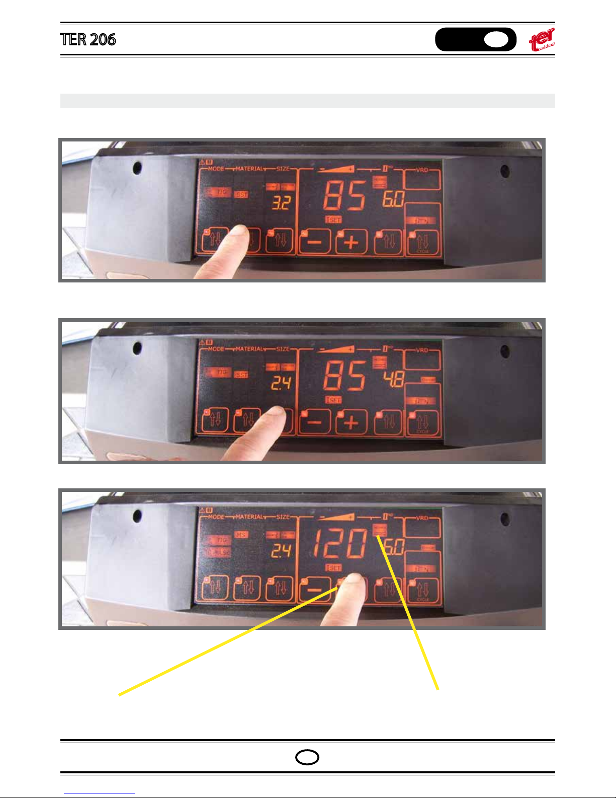
TIG SYNERGIC MODE - Setting
With the second pushbutton select the material type
With the third pushbutton select the tungsten size
Set with pushbuttons “+” or “-” the required wel-
ding current. Current level limits depend from
the choosed program
Page 21
OPERATING MANUAL
English
GB
GB
TIG SYNERGIC MODE - Setting
With the second pushbutton select the material type
With the third pushbutton select the tungsten size
Set with pushbuttons “+” or “-” the required welding current. Current level limits depend from
the choosed program
The basic material thickness setting is strictly
connected with the selected current and
material type
Page 22
OPERATING MANUAL
English
GB
GB
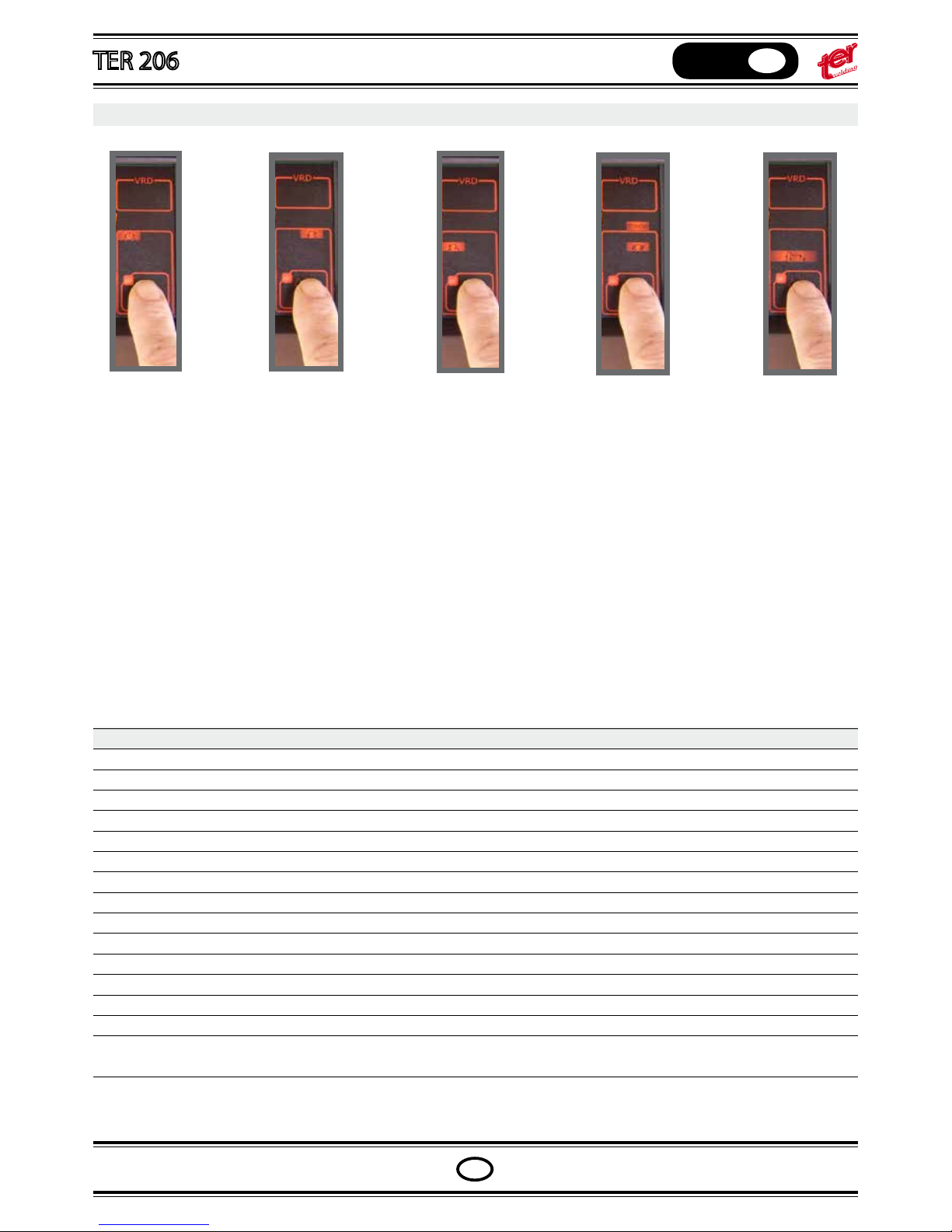
SWITCH CYCLES – Setting
TIMER
The current stops
after the set time;
can restart with a
new arc strike.
Available both
with lift and HF
arc strike mode
TWO STEPS
The current starts
when the torch
switch drives the
cycle and stops
when it is released. Up and down
slopes are not
allowed
TWO STEP
SLOPE
The current starts
when the torch
switch drives the
cycle and stops
with a down slope
when the torch
switch is released
FOUR
STEPS
The current starts
when the torch
switch drives the
cycle and stops
when the torch
switch is pressed
again
FOUR
STEPS SLOPE
The current starts
at level 1 at the
rst torch switch
pressure; slope
rise up releasing
the torch switch.
Down slope to
current I3 at
second switch
pressure and
stop with switch
release.
NOTES:
In synergic tig setting all the parameters change according to program and current:
PREGAS x at 0,1 sec
UP slope automatic depending from down slope
CURRENT 1 automatic sinergic
CURRENT 3 automatic sinergic
DOWN slope automatic sinergic
POST GAS automatic sinergic
PULSE FREQUENCY automatic sinergic
PULSE BALANCE automatic sinergic
TIMER variable (select the icon with second level pushbutton)
PULSE PEAK automatic sinergic
PULSE LOW CURRENT automatic sinergic
THE USER DOES NOT NEED TO ADJUST THE WHOLE PARAMETERS BECAUSE THEY ARE ALREADY SET AT THE OPTIMAL VALUE
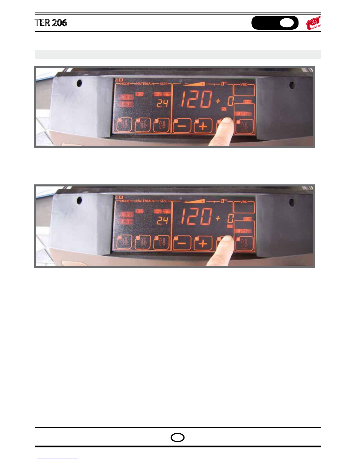
CORRECTION OF THE SYNERGIC PARAMETERS
If expert users need any particular adjustment, corrections of down slope, frequency, post gas are allowed chan-
ging the program values.
Press the second level pushbutton up to the icon “SLOPE DOWN” ligth on, than adjust the parameters between
-50% and +50% by pressing pushbutton “+” or “ –“.
Press the second level pushbutton up to the icon “POST GAS” ligth on, than adjust the parameters between -50%
and +50% by pressing pushbutton “+” or “ –“.
Follow the same procedure for frequency.
Page 23
OPERATING MANUAL
English
GB
GB
CORRECTION OF THE SYNERGIC PARAMETERS
If expert users need any particular adjustment, corrections of down slope, frequency, post gas are allowed changing the program values.
Press the second level pushbutton up to the icon “SLOPE DOWN” ligth on, than adjust the parameters between
-50% and +50% by pressing pushbutton “+” or “ –“.
Press the second level pushbutton up to the icon “POST GAS” ligth on, than adjust the parameters between -50%
and +50% by pressing pushbutton “+” or “ –“.
Follow the same procedure for frequency.
Page 24
OPERATING MANUAL
English
GB
GB
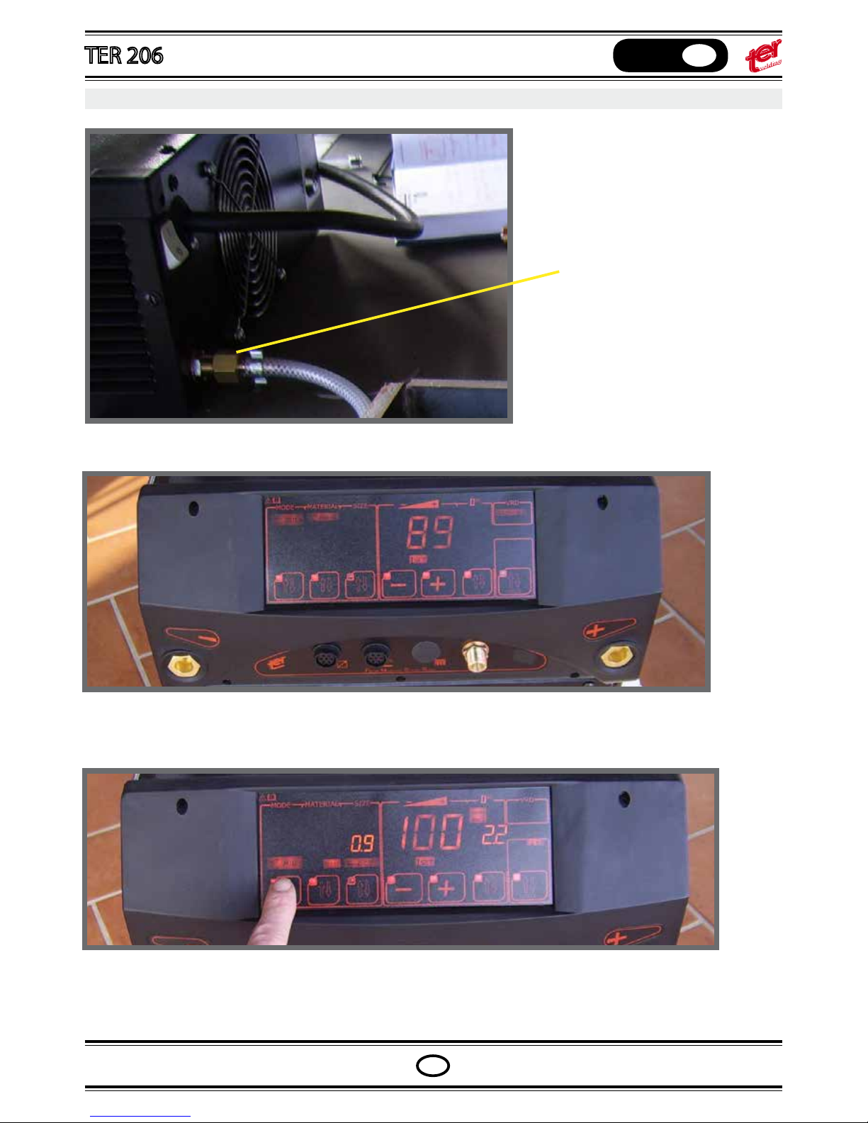
Connect the gas bottle to the back
side gas input nipple
The mig and puls mig versions include the second connector for spool on gun tting
Select mig
MIG WELDING – machine setting
or puls mig
Connect the auxiliar connector
and the gas hose
SPOOL ON GUN CONNECTION
Page 25
OPERATING MANUAL
English
GB
GB
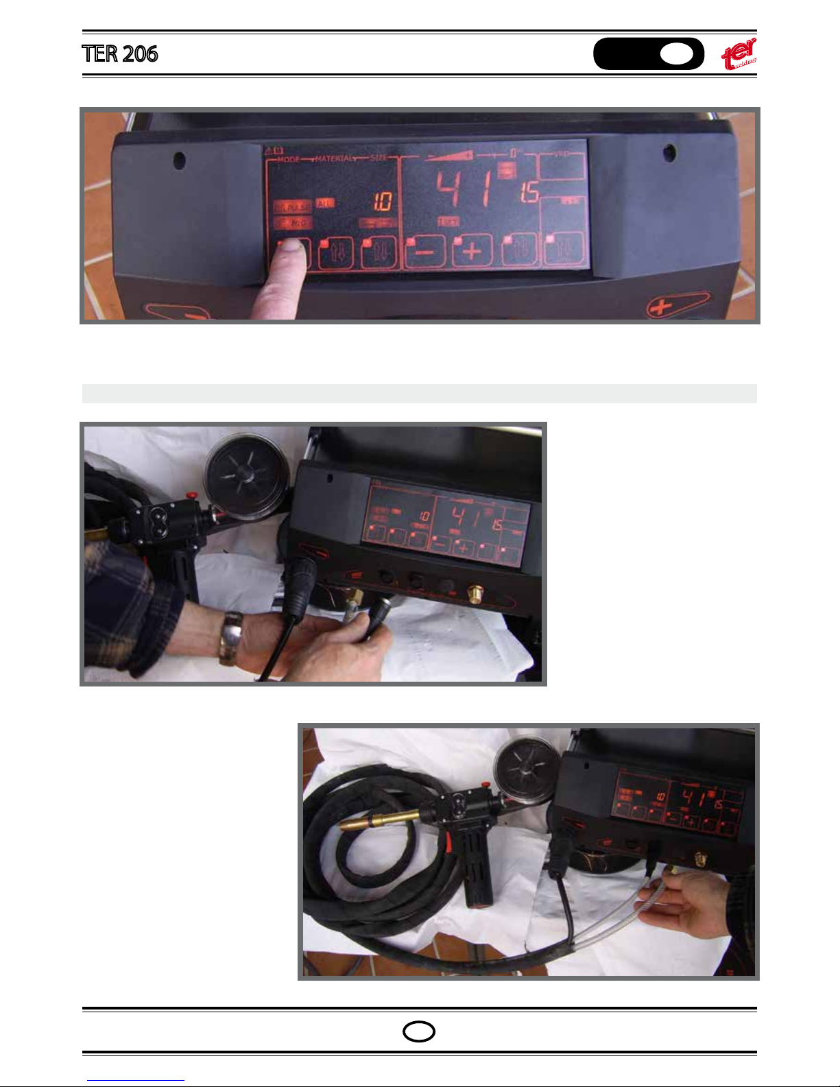
or puls mig
Connect the spool on gun, main
cable, to positive or negative polarity (according to the wire type,
ex.: innershield wire must be connected to the negative polarity)
Connect the auxiliar connector
and the gas hose
SPOOL ON GUN CONNECTION
Page 26
OPERATING MANUAL
English
GB
GB
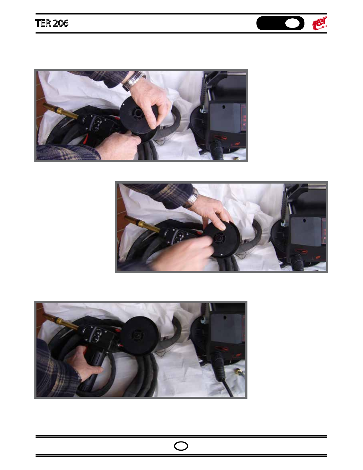
Held the spool and insert a
wire portion up to the driving
rools of the gun
Insert the spool into the spool
holder and brake it xing the
shaft clockwise
Press the torch switch; the
wire should carried out up to
the tip orice
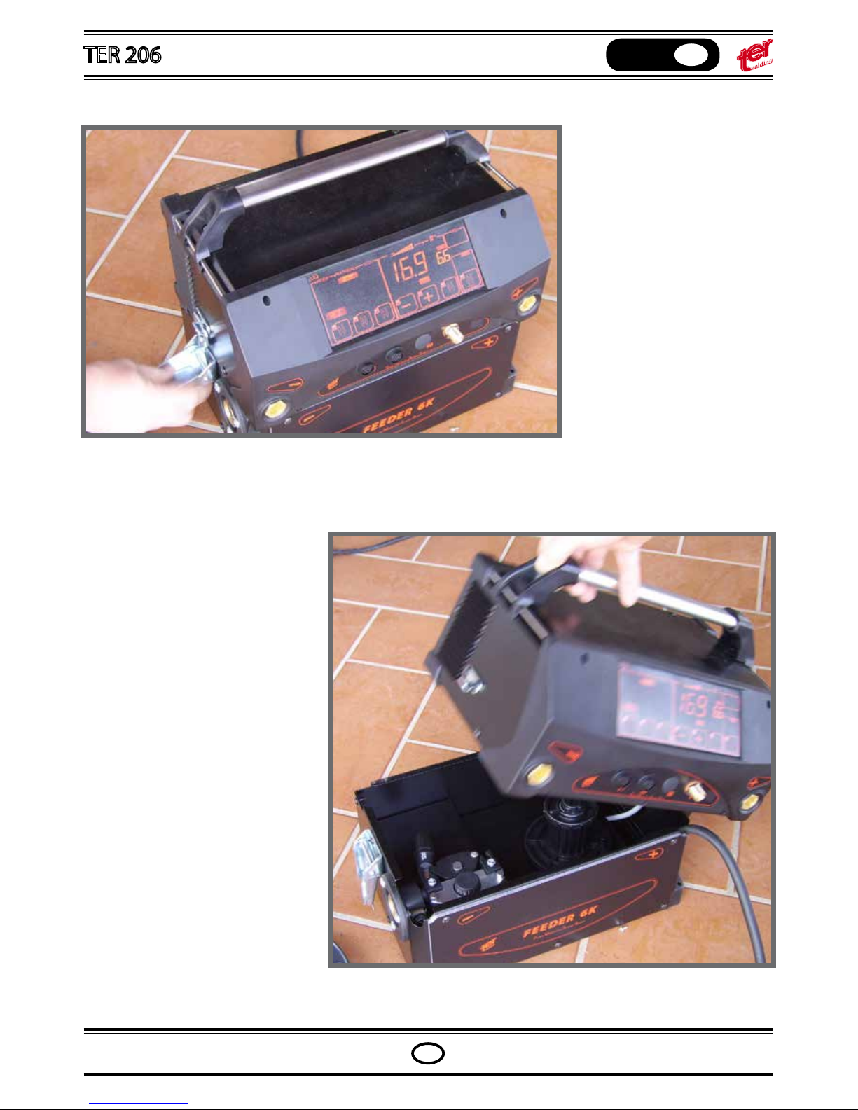
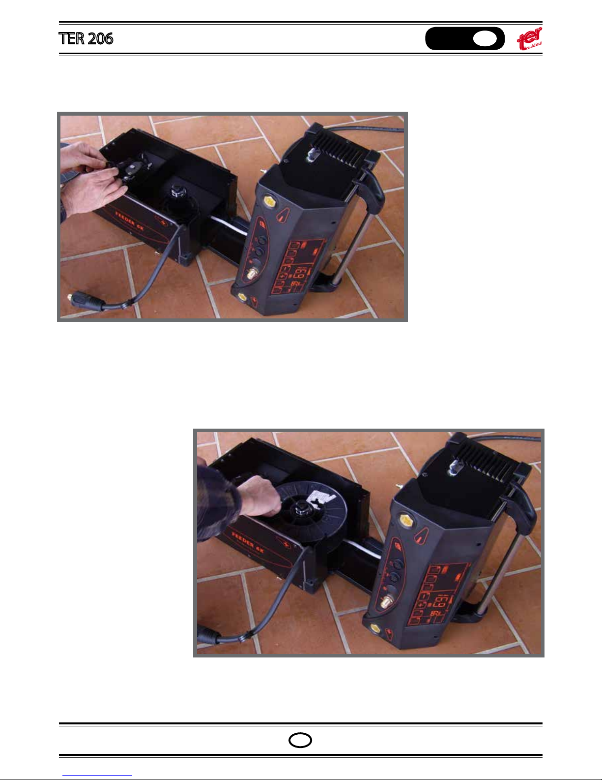
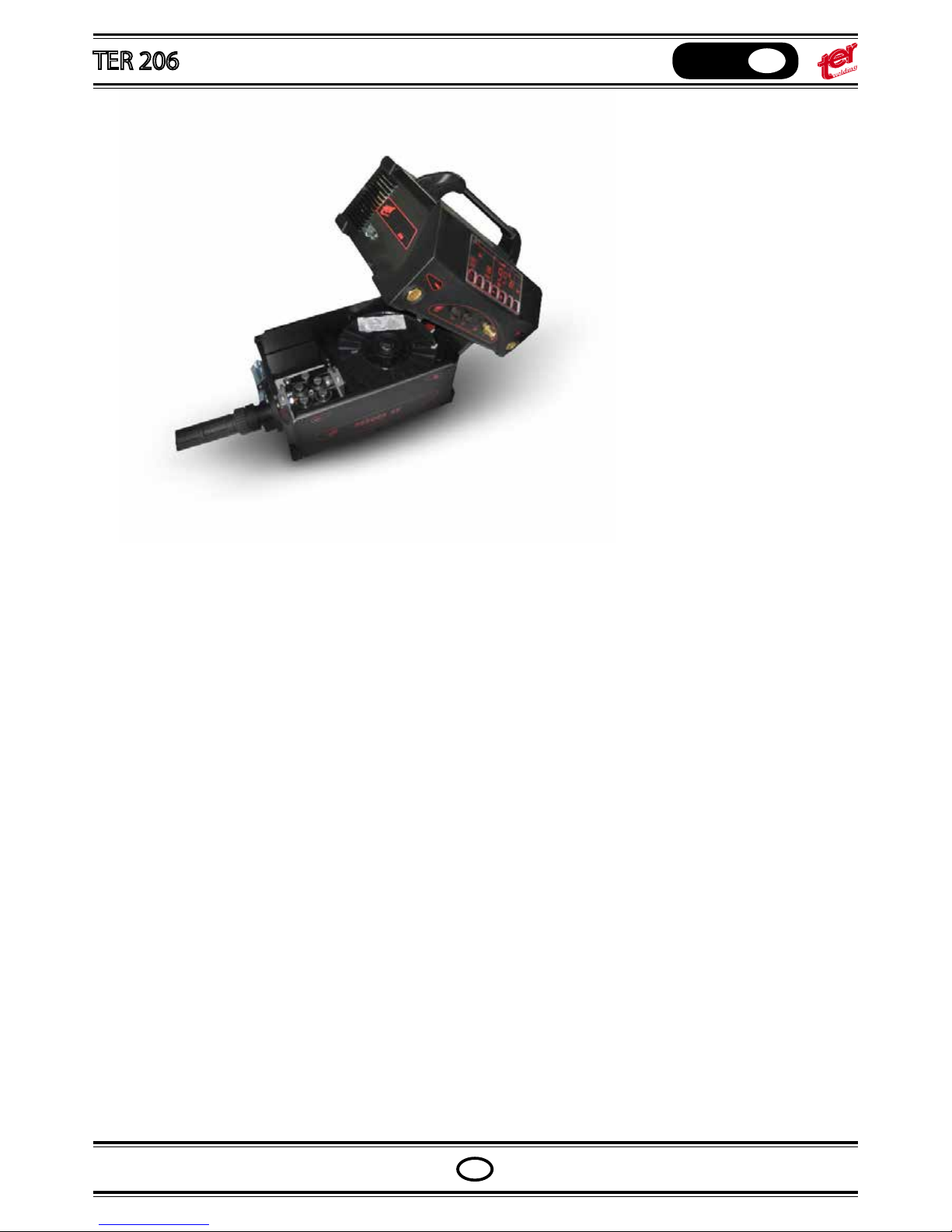
Open the machine toward the
right side
FEEDER 6K CONNECTION
Page 27
OPERATING MANUAL
English
GB
GB
Unlock the machine
Open the machine toward the
right side
FEEDER 6K CONNECTION
Page 28
OPERATING MANUAL
English
GB
GB
Check if the driving rolls
match the appropriate wire
diameter
Push the wire between the
driving rolls up to see it outside the Euro torch connector.
Close the upper rolls with the
shaft
Page 29
OPERATING MANUAL
English
GB
GB
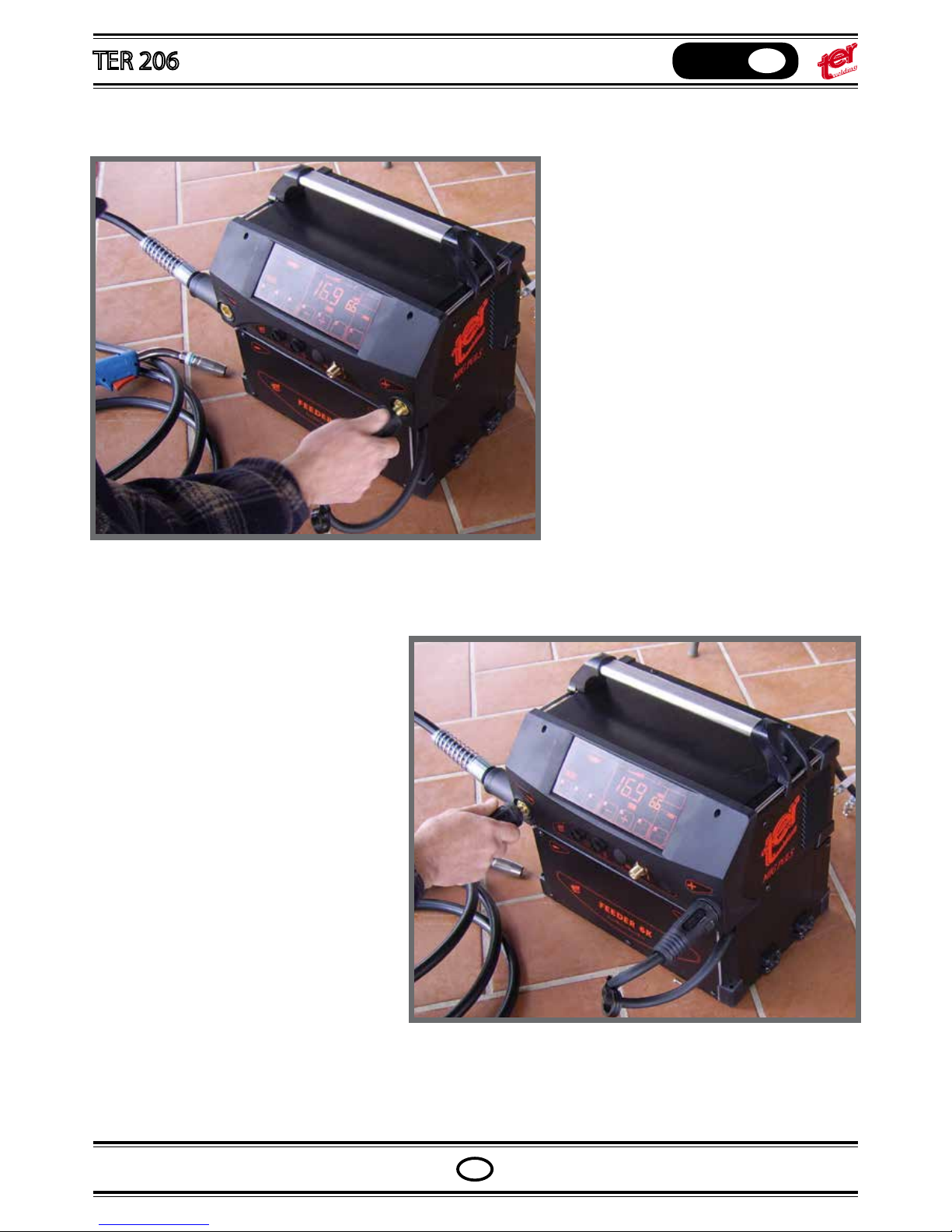
Connect the mig gun
Page 30
OPERATING MANUAL
English
GB
GB
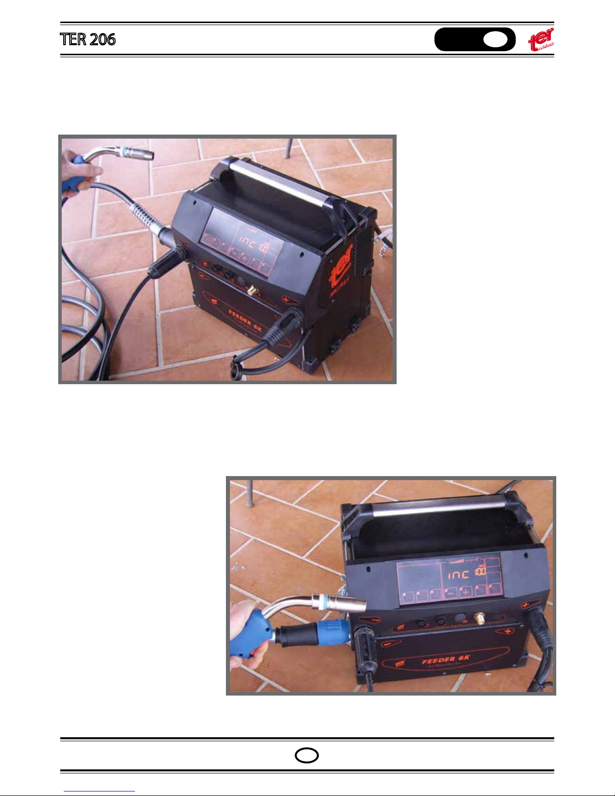
Close the machine and connect the main
cable to positive or negative polarity
Connect the workpiece cable
Release the switch and push it
again.
The wire will drive out continuosly
at a speed of approx 10 meters/min
until the switch remain pressed
Page 31
OPERATING MANUAL
English
GB
GB
Press the gun switch; the wire
drives out slowly for 5 seconds,
than stops and the frontal panel
shows inc 10: that means the state
of inch wire is active
Release the switch and push it
again.
The wire will drive out continuosly
at a speed of approx 10 meters/min
until the switch remain pressed
Page 32
OPERATING MANUAL
English
GB
GB
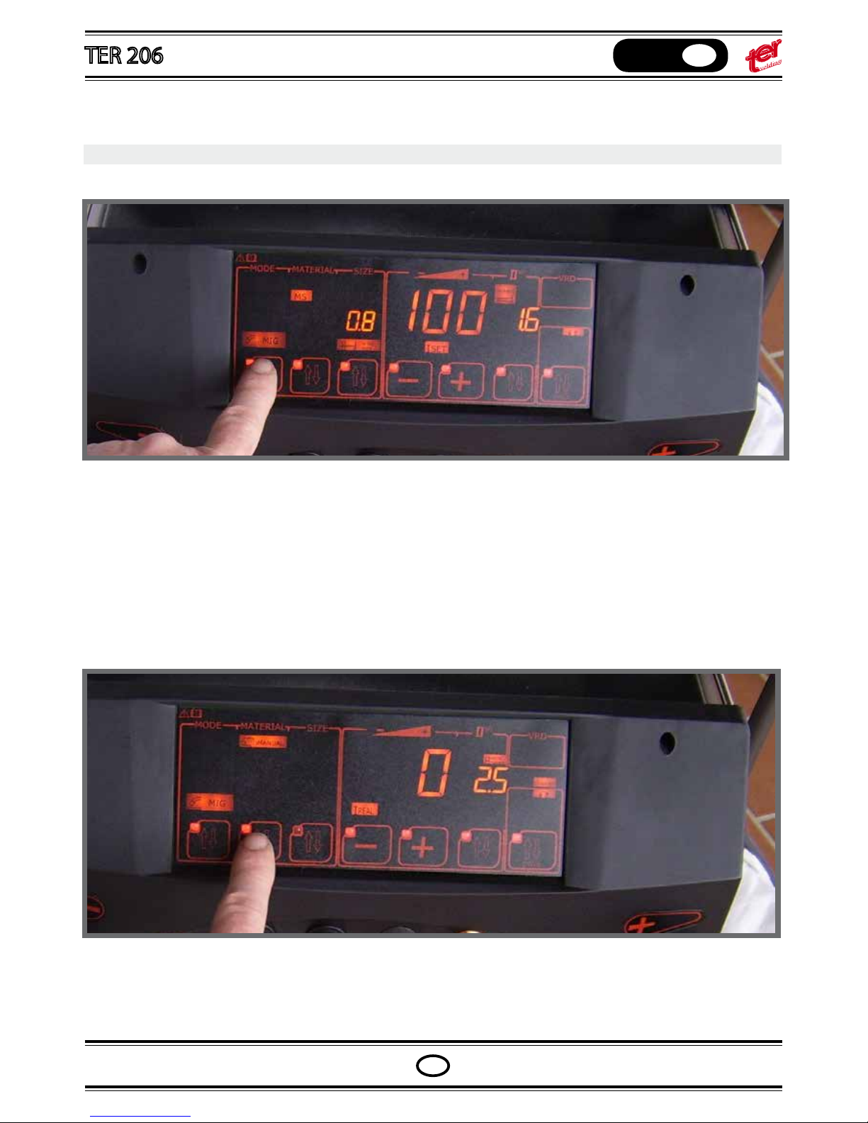
Press the rst pushbutton - Select “MIG”
Press the second pushbutton - Select “MANUAL”
MIG SETTING – Manual mode
Set the welding voltage pressing the “+ “and “–“ pushbuttons
Press the second level pushbutton; the icon “WIRE SPEED” ash to show it’s waiting for input data
Page 33
OPERATING MANUAL
English
GB
GB
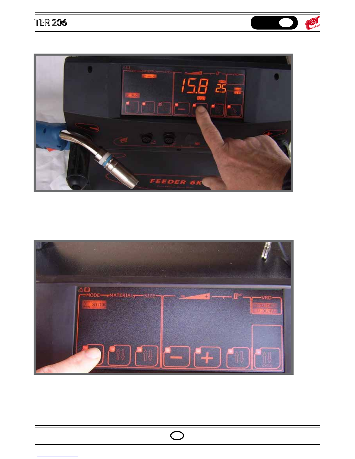
Set the welding voltage pressing the “+ “and “–“ pushbuttons
Press the second level pushbutton; the icon “WIRE SPEED” ash to show it’s waiting for input data
Page 34
OPERATING MANUAL
English
GB
GB
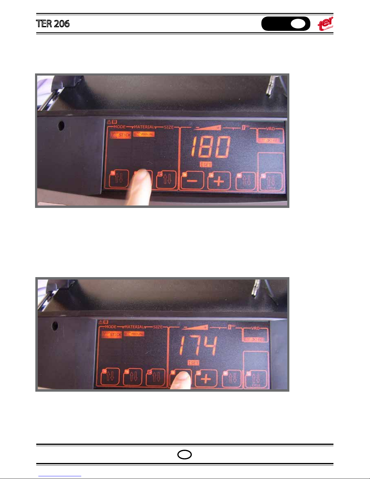
Set the wire speed pressing the “+ “and “–“ pushbuttons
If the “+” and “–“ pushbuttons aren’t driven, the setting come back to the voltage adjustment and the icon “WIRE
SPEED” stops to ash
Select the cycle: rst icon is spot welding (TIMER)
Second icon is two steps cycle.
Weld when the gun switch remain pressed. Post gas can be adjusted with the second level pushbutton
Page 35
OPERATING MANUAL
English
GB
GB
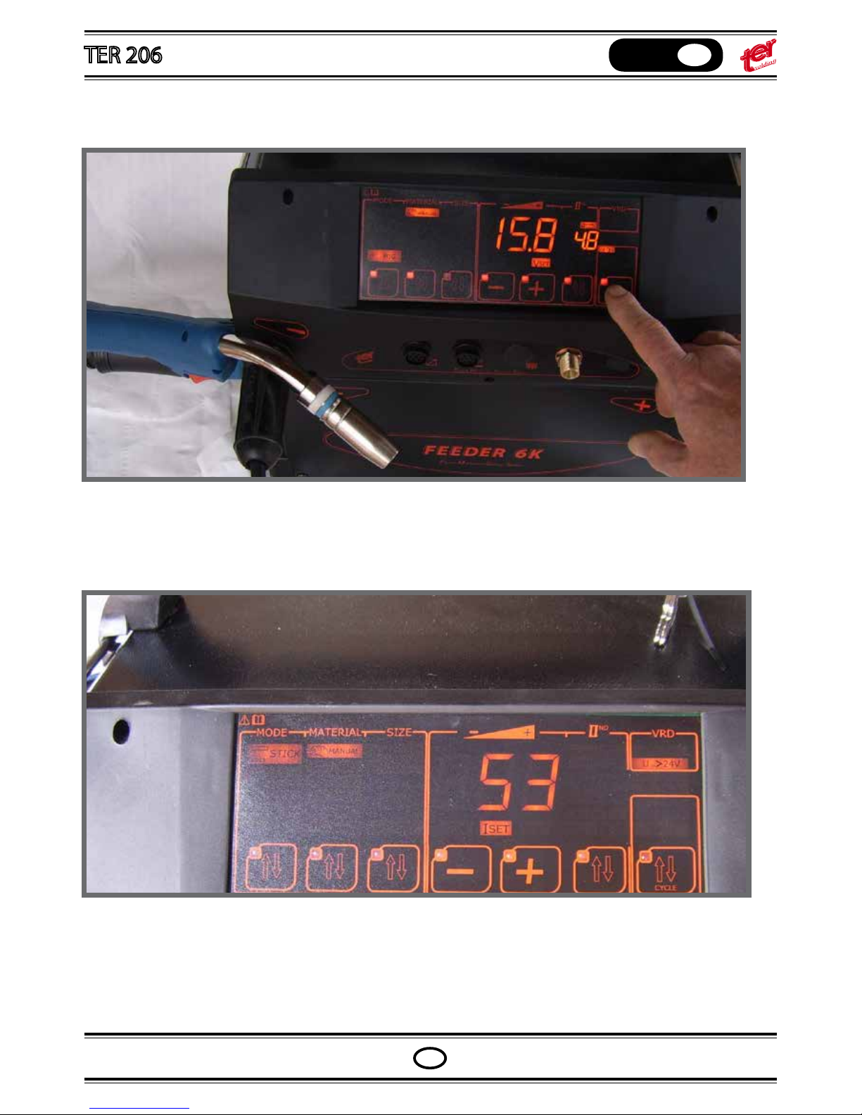
Select the cycle: rst icon is spot welding (TIMER)
Second icon is two steps cycle.
Weld when the gun switch remain pressed. Post gas can be adjusted with the second level pushbutton
Page 36
OPERATING MANUAL
English
GB
GB
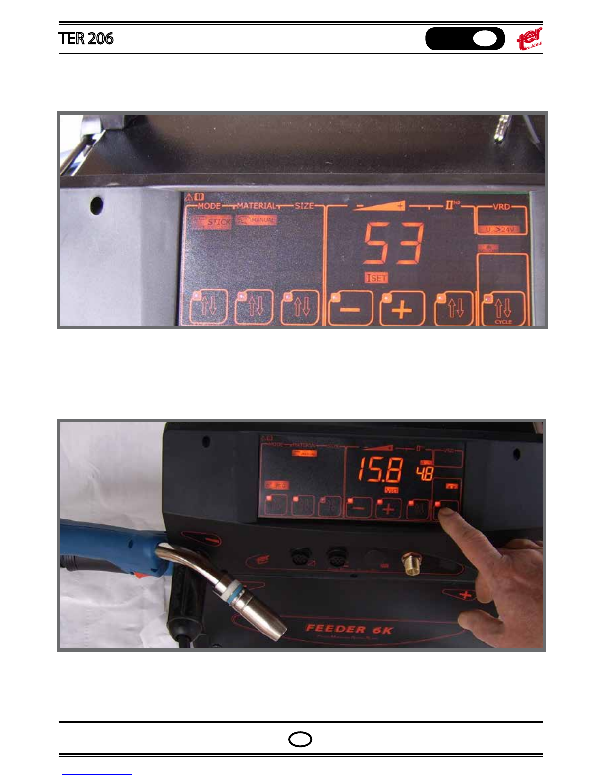
Third icon is 4 steps cycle.
The rst switch press releases the pregas protection; once the switch is released, the welding starts and it stops at
the second switch press. The gas ow continue unti the switch is totally released.
Forth icon is two step with down slope, (when the switch is released the current slow down to nal current with
down slope.
Fifth icon is complete cycle four steps with slopes.
At the rst switch press, the welding starts with the initial current (lower than the welding current);
once the switch is released, the current rise up (slope) to the set welding current.
The current remains at the nal current until the switch is totally released.
At the second press, the current slow down to the nal current with slope (adjustable with second level pushbut-
ton).
Note : during the welding, the icon “V SET” blank and ligh on the icon I REAl, the main digital instrument shows the
real welding current.
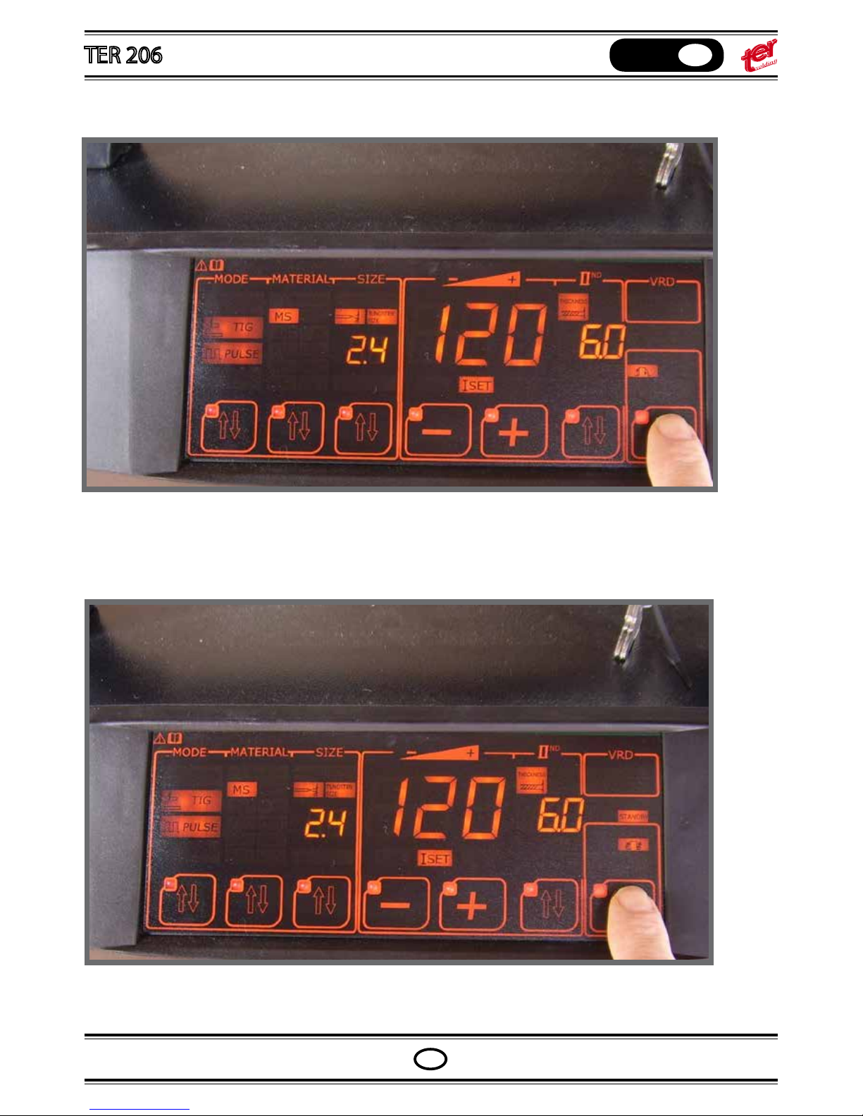
Press for 5 seconds the second level pushbutton.
The main display write “BBT” and the right hand side display will show the actual BBT time
BURN BACK TIME
It is the time, at the end of welding, allowing the burning of the wire up to 2-5 mm from the work piece.
Page 37
OPERATING MANUAL
English
GB
GB
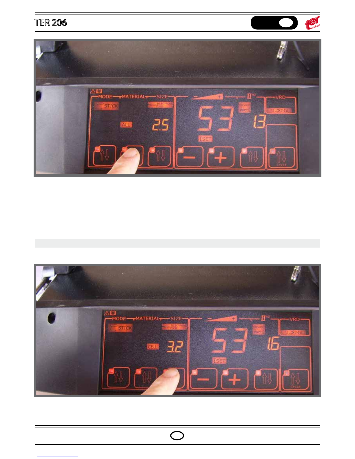
Fifth icon is complete cycle four steps with slopes.
At the rst switch press, the welding starts with the initial current (lower than the welding current);
once the switch is released, the current rise up (slope) to the set welding current.
The current remains at the nal current until the switch is totally released.
At the second press, the current slow down to the nal current with slope (adjustable with second level pushbutton).
Note : during the welding, the icon “V SET” blank and ligh on the icon I REAl, the main digital instrument shows the
real welding current.
Press for 5 seconds the second level pushbutton.
The main display write “BBT” and the right hand side display will show the actual BBT time
BURN BACK TIME
It is the time, at the end of welding, allowing the burning of the wire up to 2-5 mm from the work piece.
Page 38
OPERATING MANUAL
English
GB
GB
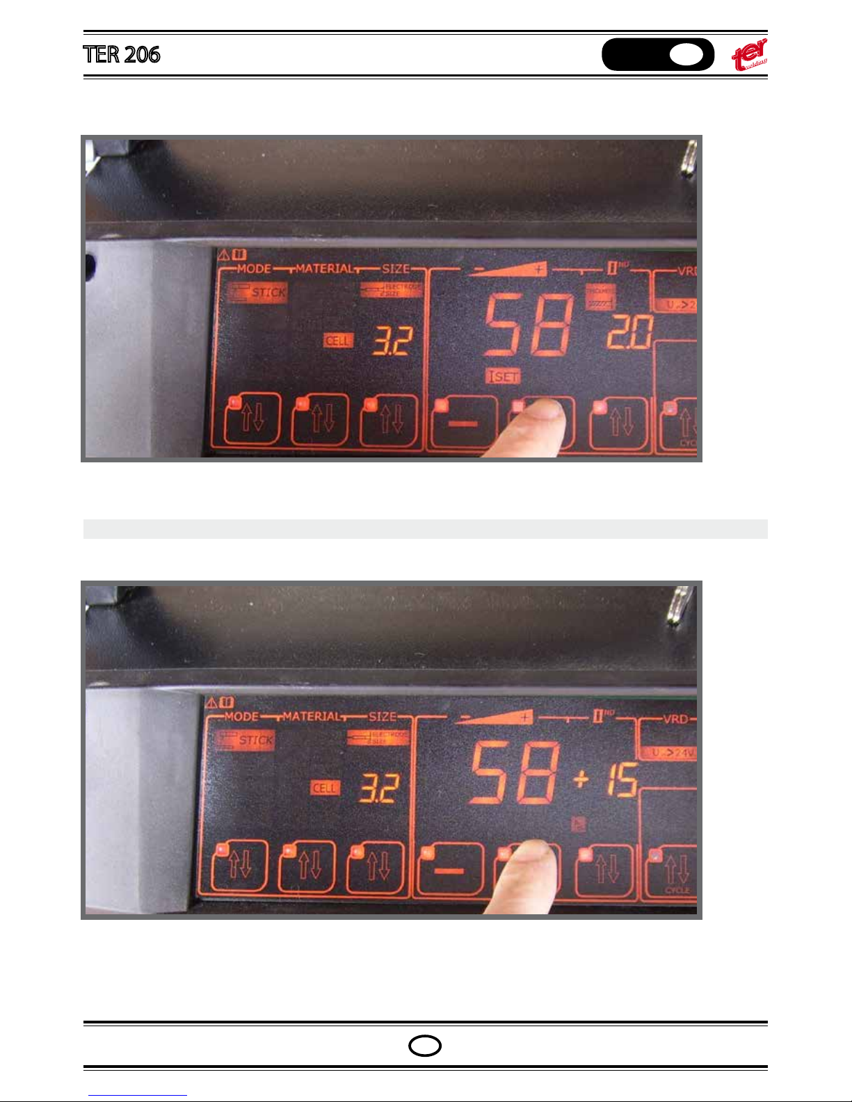
Adjust the BBT with “+” and “–“ pushbuttons, and try the new value in welding.
Once the nal setting is done, press the second level pushbutton again, back to the main setting menù.
Press the second pushbutton - Select the material type
MIG SETTING – Synergic mode
Press the third pushbutton - Select the wire diameter
Set the welding current controlling the workpiece thickness or viceversa
Page 39
OPERATING MANUAL
English
GB
GB
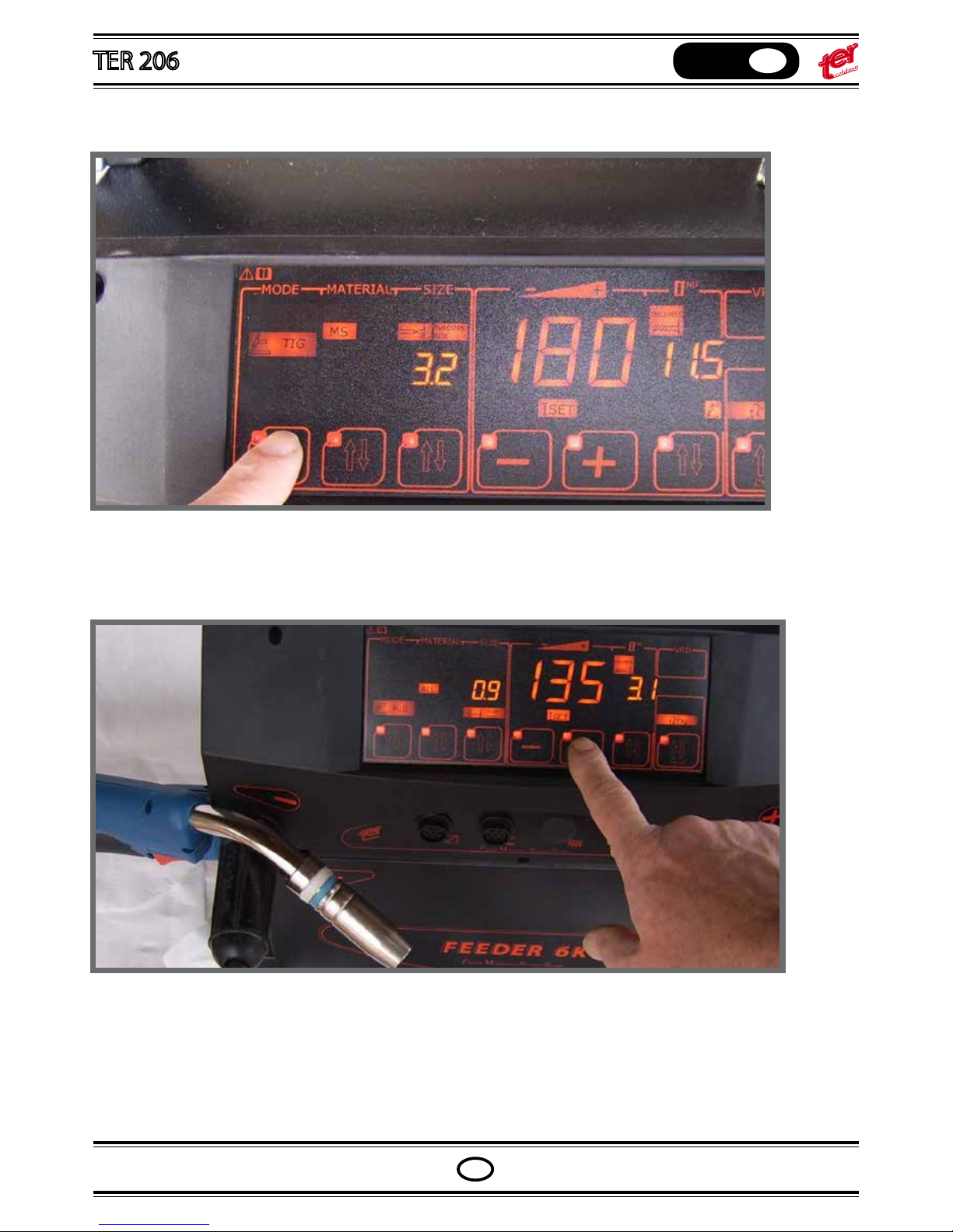
Press the third pushbutton - Select the wire diameter
Set the welding current controlling the workpiece thickness or viceversa
Page 40
OPERATING MANUAL
English
GB
GB
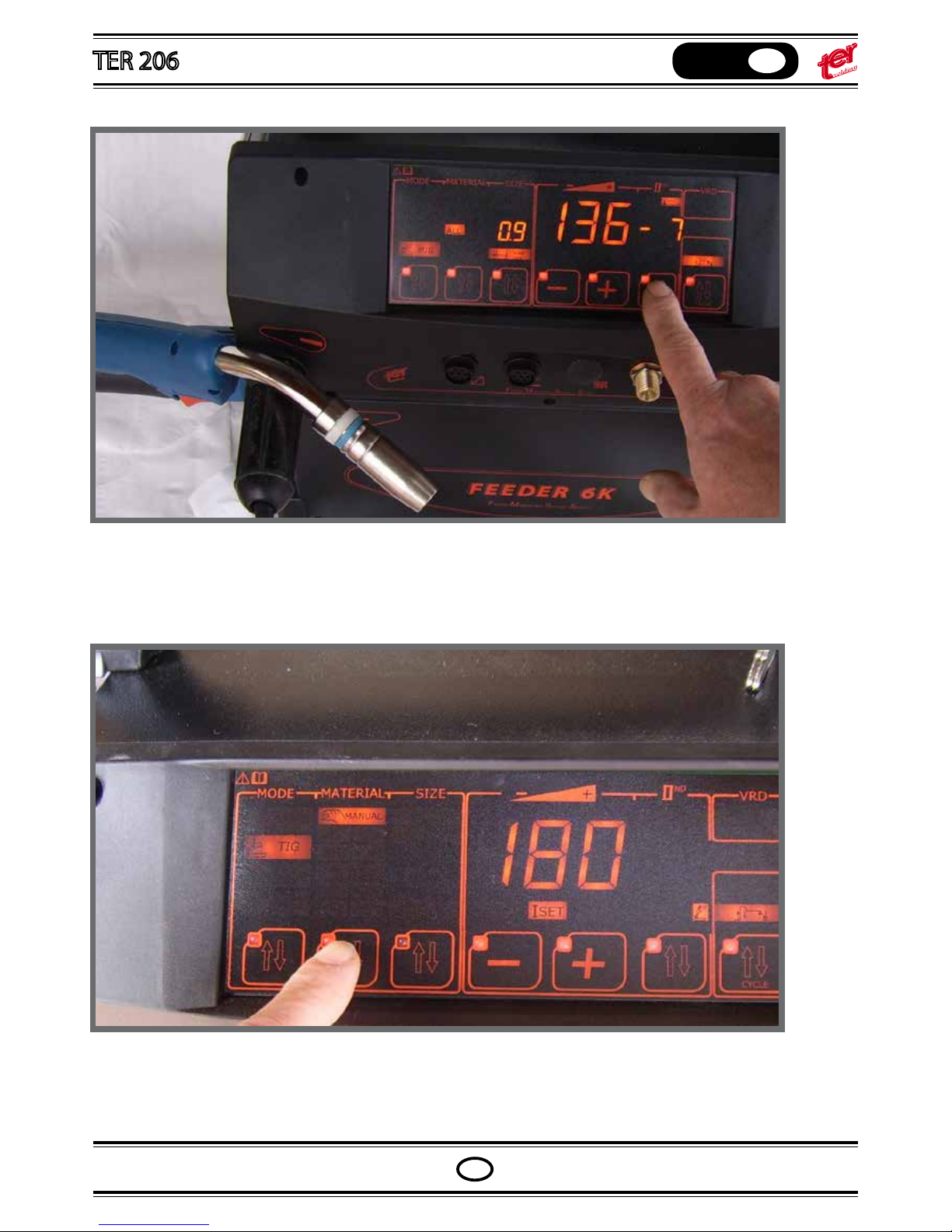
Press the second level pushbutton to light the arc length icon on
Adjust the arc length pressing the pushbuttons “+” and “-”
Press twice the second level pushbutton to ligth the icon of the inductance on
Adjust the inductance pressing the pushbuttons “+” and “-”
Note:
in the synergic setting mode, all the welding parameters are pre-set according to the chosed program and the
current setting.
The inputs related to arc length, inductance, bbt, post gas, slope, initial and nal current strictly depend from pro-
gram and current settings.
Page 41
OPERATING MANUAL
English
GB
GB
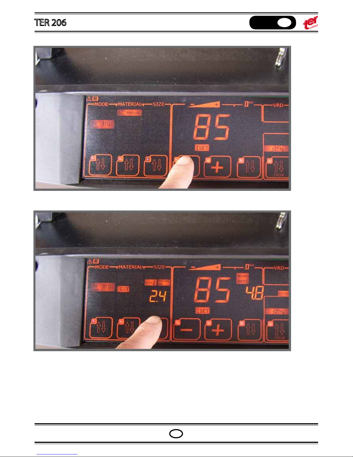
Press twice the second level pushbutton to ligth the icon of the inductance on
Adjust the inductance pressing the pushbuttons “+” and “-”
Note:
in the synergic setting mode, all the welding parameters are pre-set according to the chosed program and the
current setting.
The inputs related to arc length, inductance, bbt, post gas, slope, initial and nal current strictly depend from program and current settings.
Page 42
OPERATING MANUAL
English
GB
GB
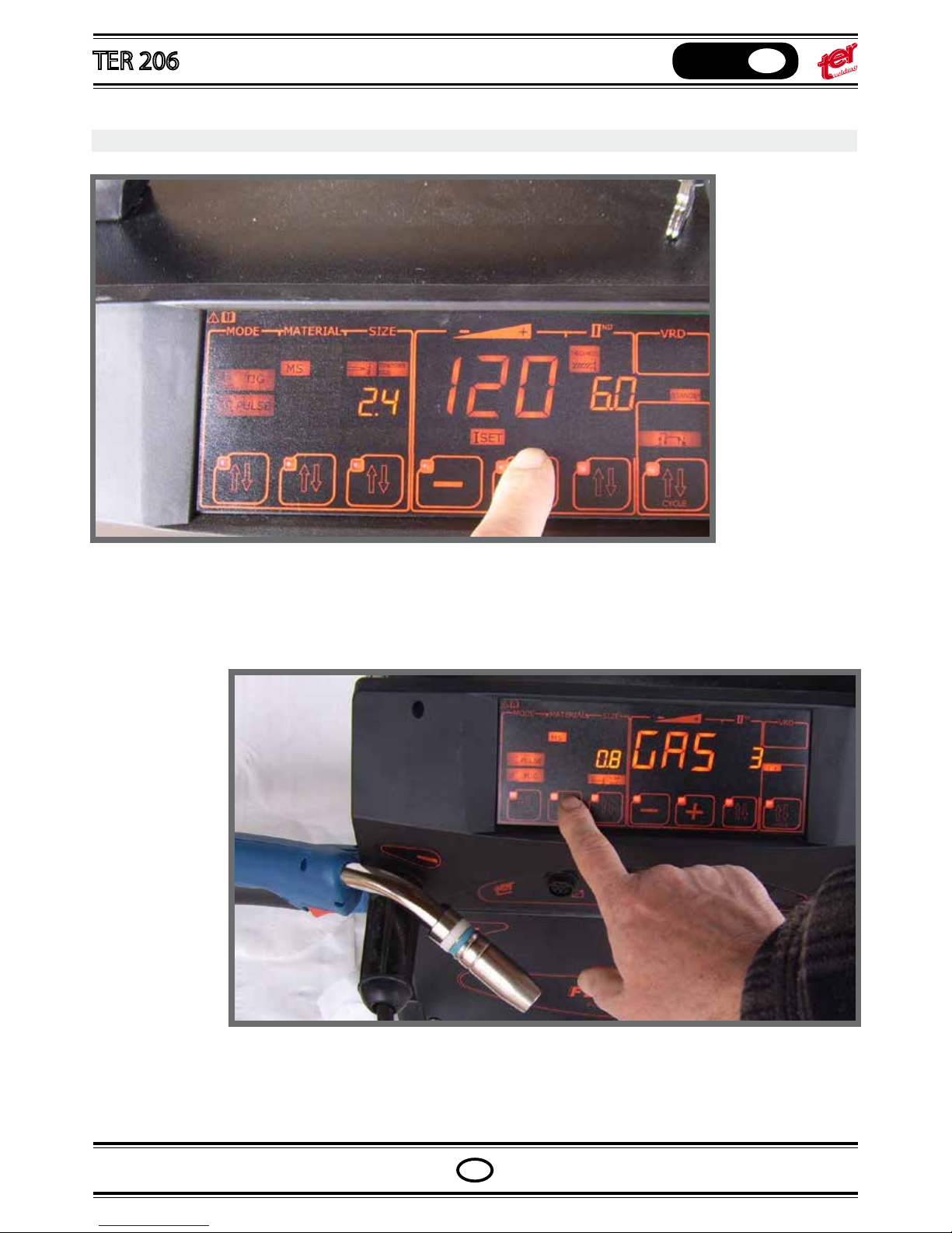
Press the rst pushbutton – Select “PULS MIG”
Press the second pushbutton - Select the material type
PULS MIG
Press the third pushbutton - Select the wire diameter and the proper gas: 1 = Argon / 2 = Mix 85/15 / 3 = Mix 92/8
/ 4 = 935/2 / 5 = 98/2
Page 43
OPERATING MANUAL
English
GB
GB
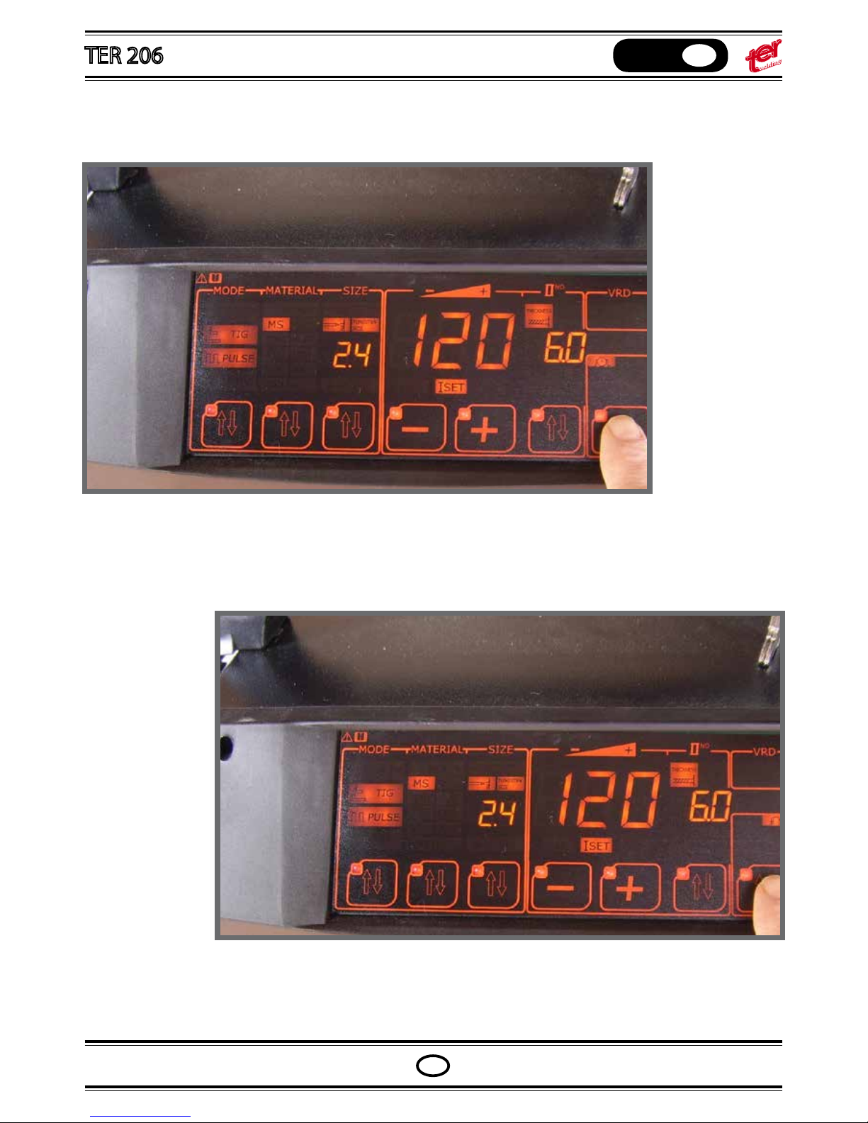
Press the third pushbutton - Select the wire diameter and the proper gas: 1 = Argon / 2 = Mix 85/15 / 3 = Mix 92/8
/ 4 = 935/2 / 5 = 98/2
Set the welding current controlling the workpiece thickness or viceversa
Page 44
OPERATING MANUAL
English
GB
GB
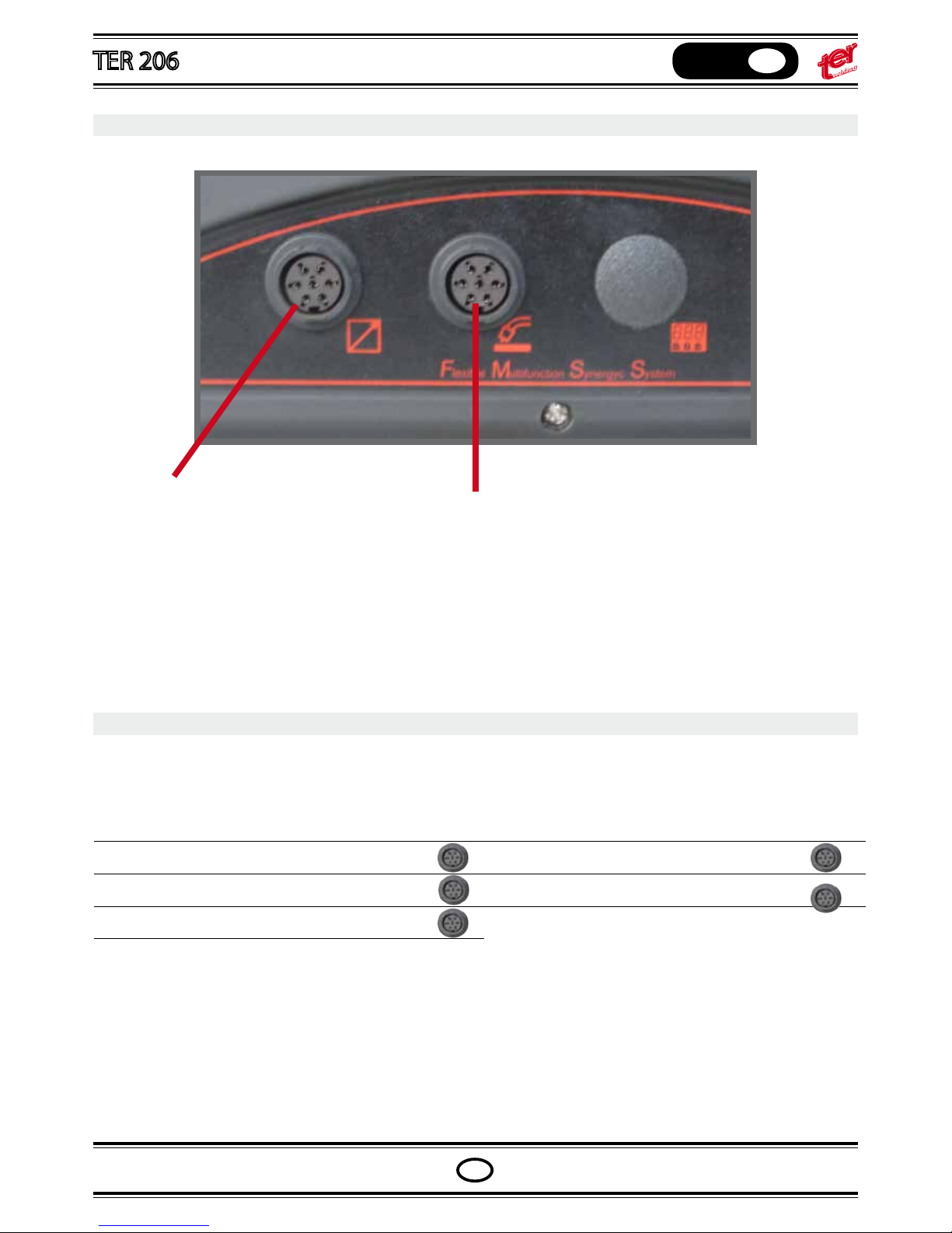
Connect the plug cod. B0045AA to the external socket,
like shown in the diagram
- Tig Torch switch
- Tig Torch switch with potentiometer
- Tig Torch switch with up/down switchers
Press the second level pushbutton to light the arc length icon on and adjust the arc length pressing the pushbuttons “+” and “-”
Press twice the second level pushbutton to ligth the icon of the inductance on and adjust the inductance pressing
the pushbuttons “+” and “-” (increase inductance value for softer arc and reduce it to obtain a harder arc)
REMOTE CONTROL
The machine automatically recognize any eventual remote control connected to the front panel socket.
Use socket 1 for Tig & MMA applications.
Use socket 2 for Mig, Pulsed Mig and Spool on gun applications.
Important: do not use the machine with both sockets connected.
REMOTE CONTROL
Note: once the remote control plug is connected, the icon “I SET” will ash and the display will show the remote
control set value.
From the machine potentiometer it is possible to adjust the maximum setting current.
The display shows the maximum setting during the adjustment and the icon “I SET” light on.
In standard Mig mode, the spool on gun remote control voltage should be adjusted at “I 20%”.
The diplay shows the set value.
Page 45
OPERATING MANUAL
English
GB
GB
Connect the plug cod. B0045AA to the external socket,
like shown in the diagram
- Tig Torch switch
- Tig Torch switch with potentiometer
- Tig Torch switch with up/down switchers
Connect the plug cod. B0045AA to the external socket,
like shown in the diagram
- external MIG feeder with digital torch
- Spool Gun with potentiometer
REMOTE CONTROL
The machine automatically recognize any eventual remote control connected to the front panel socket.
Use socket 1 for Tig & MMA applications.
Use socket 2 for Mig, Pulsed Mig and Spool on gun applications.
Important: do not use the machine with both sockets connected.
REMOTE CONTROL
Note: once the remote control plug is connected, the icon “I SET” will ash and the display will show the remote
control set value.
From the machine potentiometer it is possible to adjust the maximum setting current.
The display shows the maximum setting during the adjustment and the icon “I SET” light on.
In standard Mig mode, the spool on gun remote control voltage should be adjusted at “I 20%”.
The diplay shows the set value.
Tig
external Mig feeder /
Spool gun torch
socket 1
socket 2
socket 1 socket 2
Page 46
OPERATING MANUAL
English
GB
GB
synergic MIG programs
STANDARD MIG SYNERGIC PROGRAMS PULS MIG SYNERGIC PROGRAMS
SG2 0,6
SG2 0,8 SG2 0,8
SG2 0,9 SG2 0,9
SG2 1,0
SST 0,6
SST 0,8 SST 0,8
SST 0,9 -
SST 1,0 -
AlMg5 0,6 -
AlMg5 0,8 -
AlMg5 0,9 -
AlMg5 1,0 AlMg5 1,0
- AlMg5 1,2
CuSi 0,8 CuSi 0,8
CuSi 0,9 -
CuSi 1,0 -
Albz8 0,8 -
ux 1,0 -
ux 1,2 -
shield 0,9 -
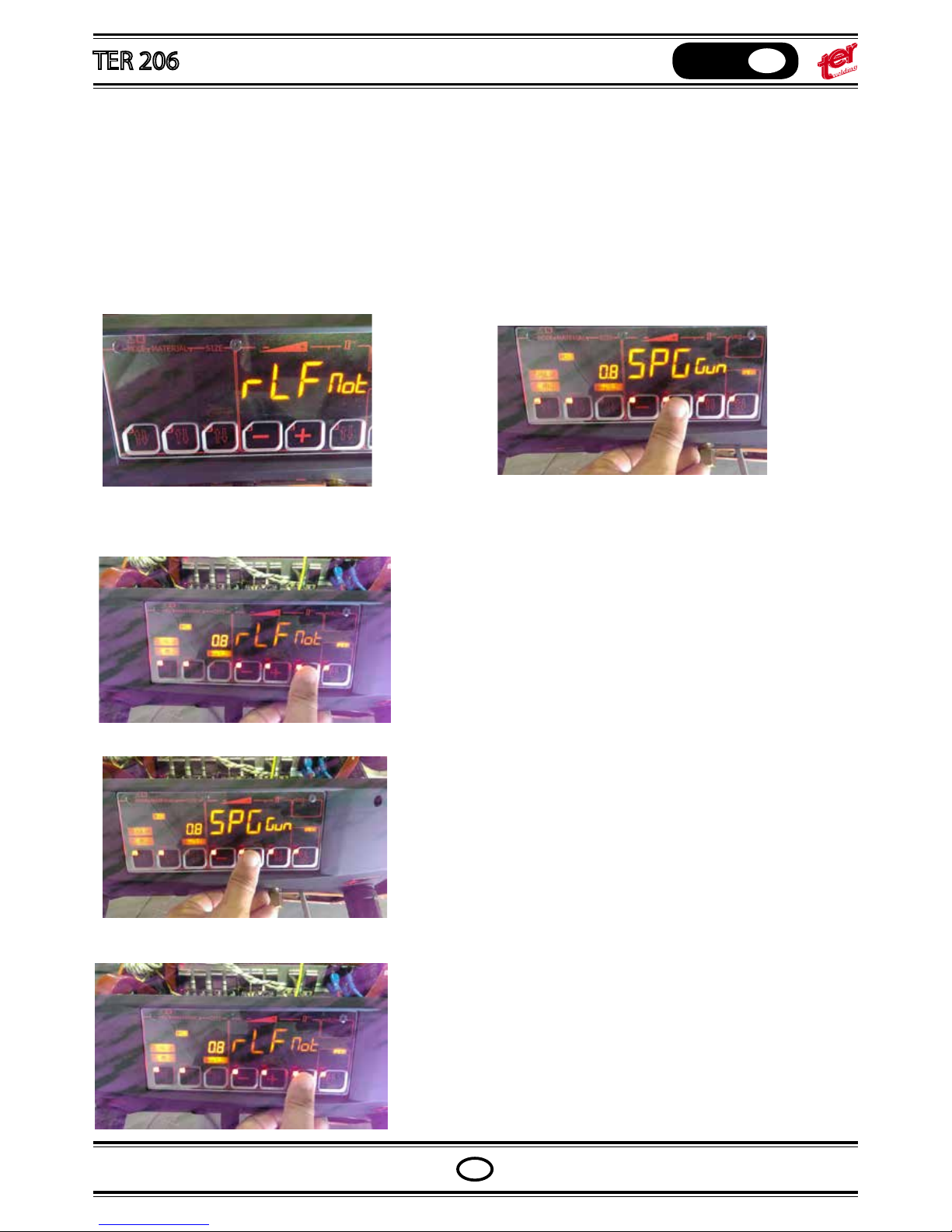
SPOOL GUN TORCH / LRF WIRE FEEDER SELECTION
The use of both device need to selection from the control panel.
At the power on the display show wich device selected:
“rLF” means the external wire feedre rLF selected “SPG” means the SPOOL GUN torch selected
selection device procedure: press and hold the selection
switch as picture untill display show the selected devce.
by the switch +/- change device : “rLF” or “SPG”
conrm selection by switch selection switch
Page 47
OPERATING MANUAL
English
GB
GB
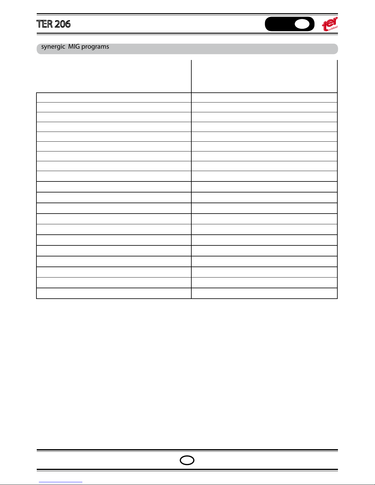
synergic MIG programs
STANDARD MIG SYNERGIC PROGRAMS PULS MIG SYNERGIC PROGRAMS
SG2 0,6
SG2 0,8 SG2 0,8
SG2 0,9 SG2 0,9
SG2 1,0
SST 0,6
SST 0,8 SST 0,8
SST 0,9 SST 1,0 -
AlMg5 0,6 AlMg5 0,8 AlMg5 0,9 AlMg5 1,0 AlMg5 1,0
- AlMg5 1,2
CuSi 0,8 CuSi 0,8
CuSi 0,9 CuSi 1,0 Albz8 0,8 ux 1,0 ux 1,2 shield 0,9 -
Page 48
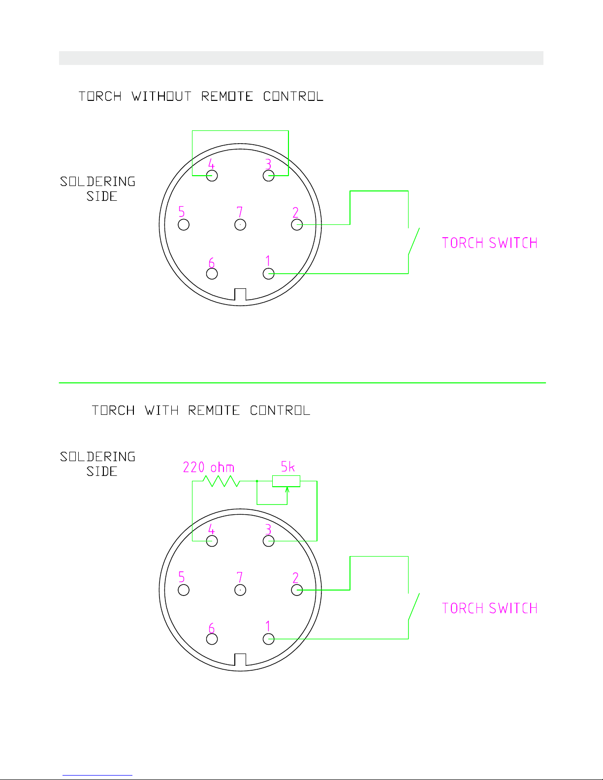
TORCH REMOTE CONTROLL CONNECTION DIAGRAM
TER 206 MACHINE SCHEMATICS
Page 49
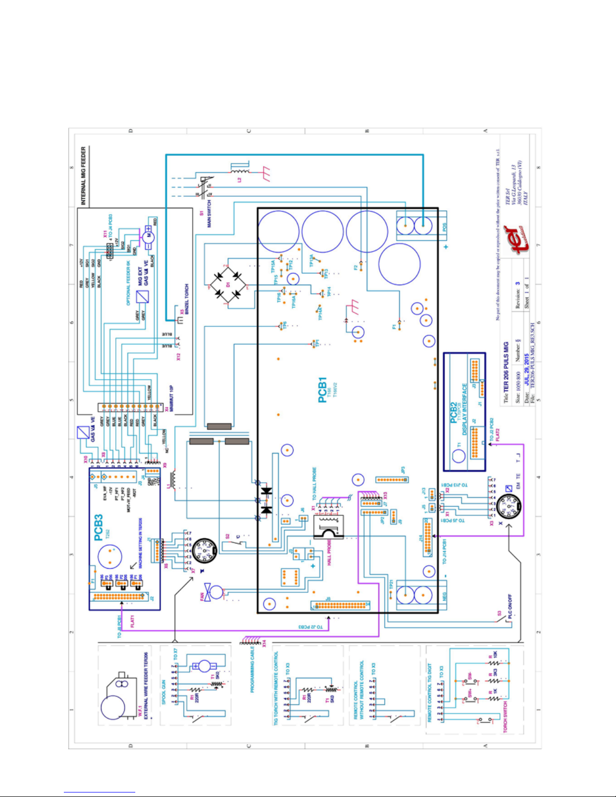
TER 206 MACHINE SCHEMATICS
1
Page 50
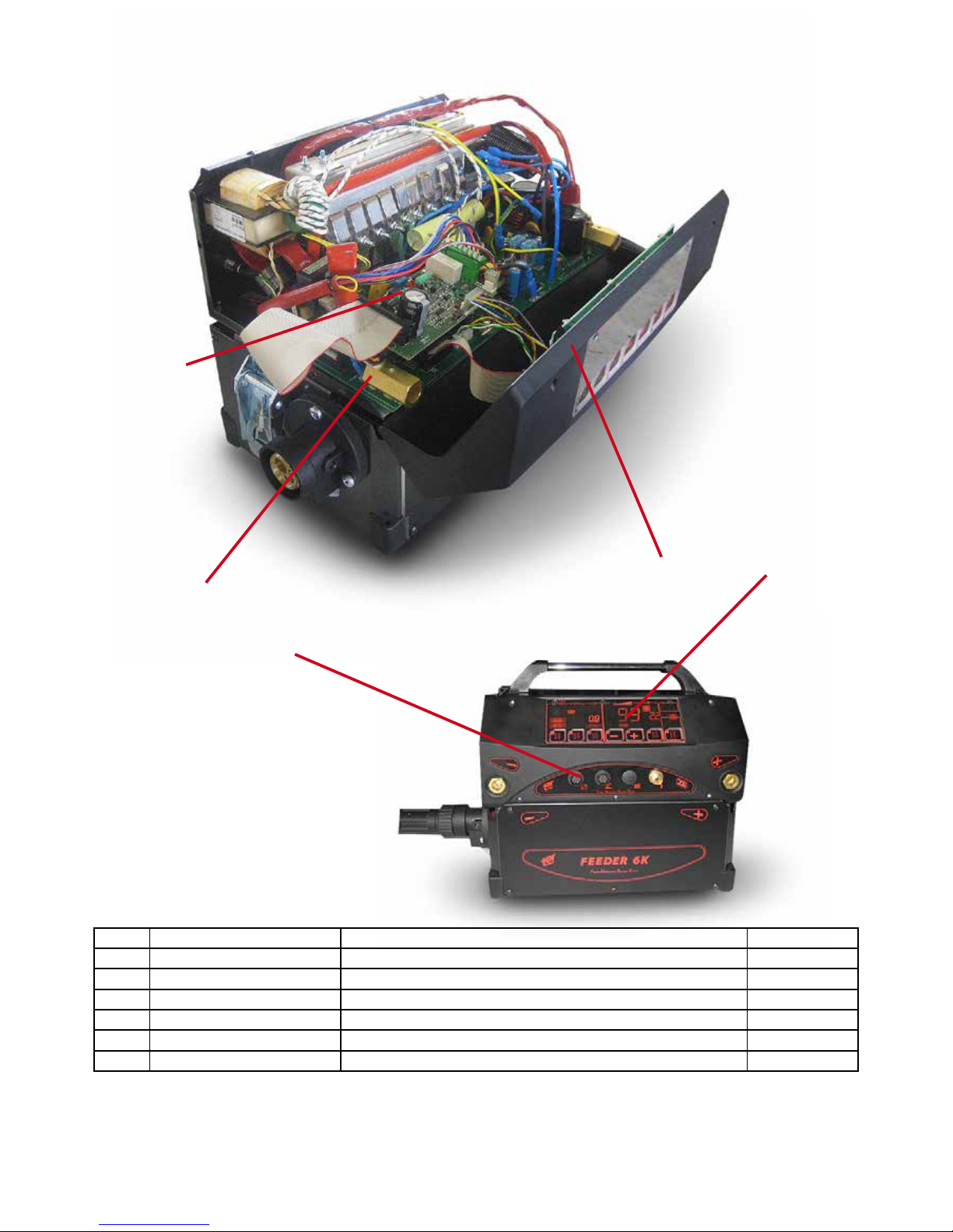
1
nr code description rif. schematics
1 T166PCB POWER CONTROL BOARD PCB1
2 T206PCB MIG MOTOR DRIVER BOARD PCB3
3 T170PCB CONTROL PANEL BOARD PCB2
4 B0035AA FEMALE PANNEL CONNECTOR 7 POLES X7, X3
5 C0508AA CPNTRL PANEL PLEXY PÈROTECTION
TER 206 spare parts
2
3
4
5
nr code description rif. schematics
1 A0026AA SSJ-15 MOTOR FEEDER MOT1
Page 51
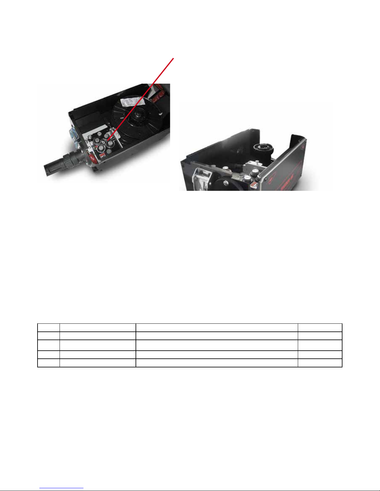
wire feeder WF206 spare parts
nr code description rif. schematics
1 A0026AA SSJ-15 MOTOR FEEDER MOT1
1
Page 52

EXTERNAL WIRE FEEDER MACHINE SCHEMATICS
Page 53
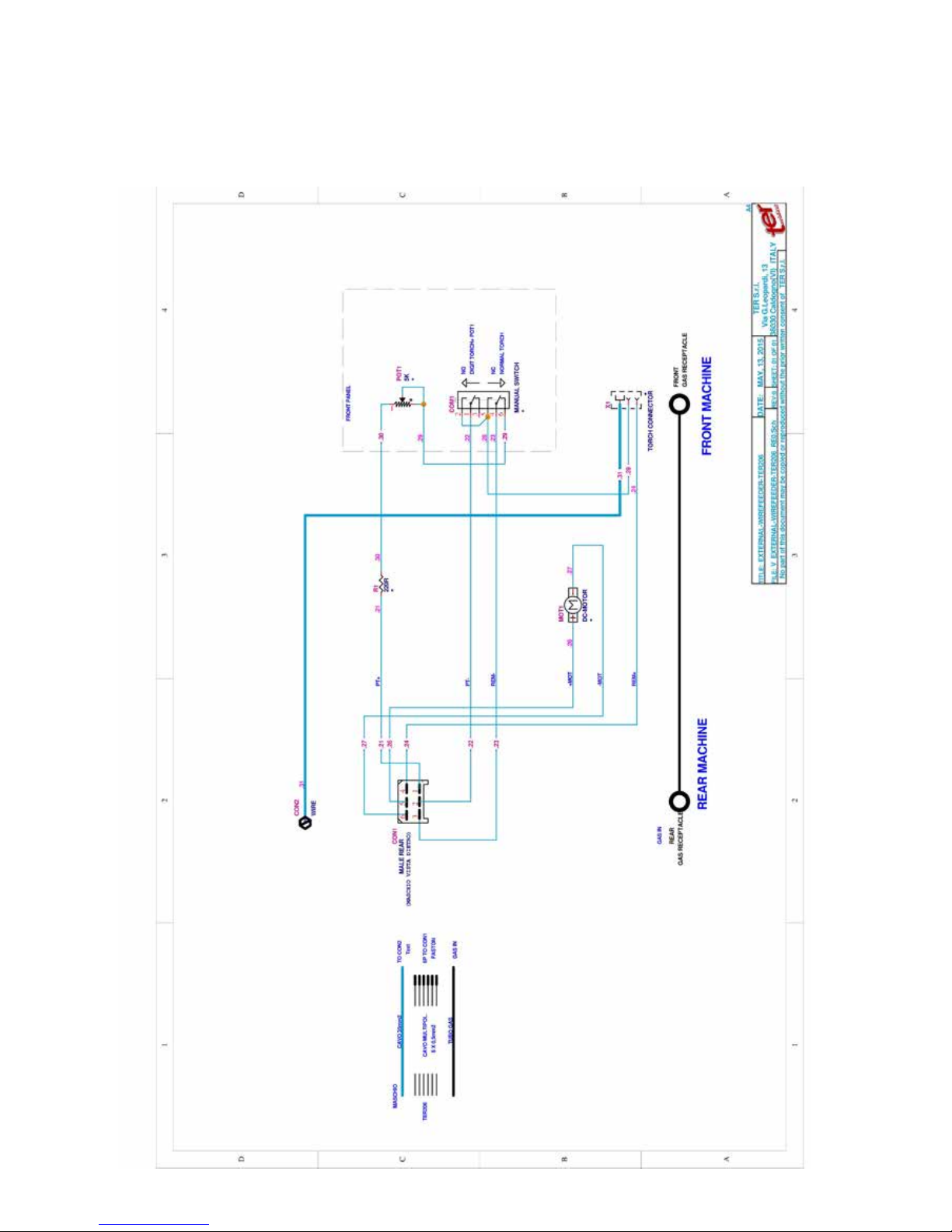
EXTERNAL WIRE FEEDER MACHINE SCHEMATICS
Page 54
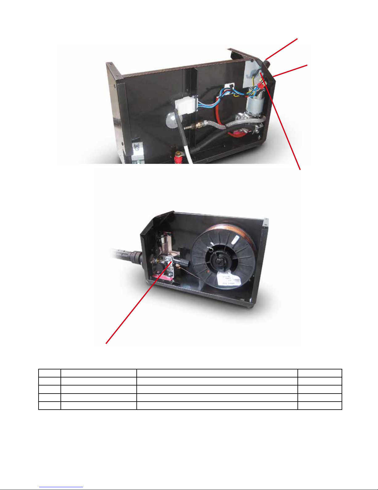
external wire feeder LRF spare parts
nr code description rif. schematics
1 A0027AA SSJ-4D MOTOR FEEDER MOT1
2 B0276AA SWITCH COM1
3 E0133AA 5KHOM POTENTIOMETER POT1
4 D0250AA KNOB FOR POTENTIOMETER POT1
1
3
2
4
Page 55

Page 56

OPERATING MANUAL
English
GB
GB
Ter srl Via Giacomo Leopardi, 13 - 36030 Caldogno (VI) ITALY •
Ph: +39 0444 586440 - Fax: +39 0444 905764 • e-mail: [email protected]
 Loading...