

Page 1
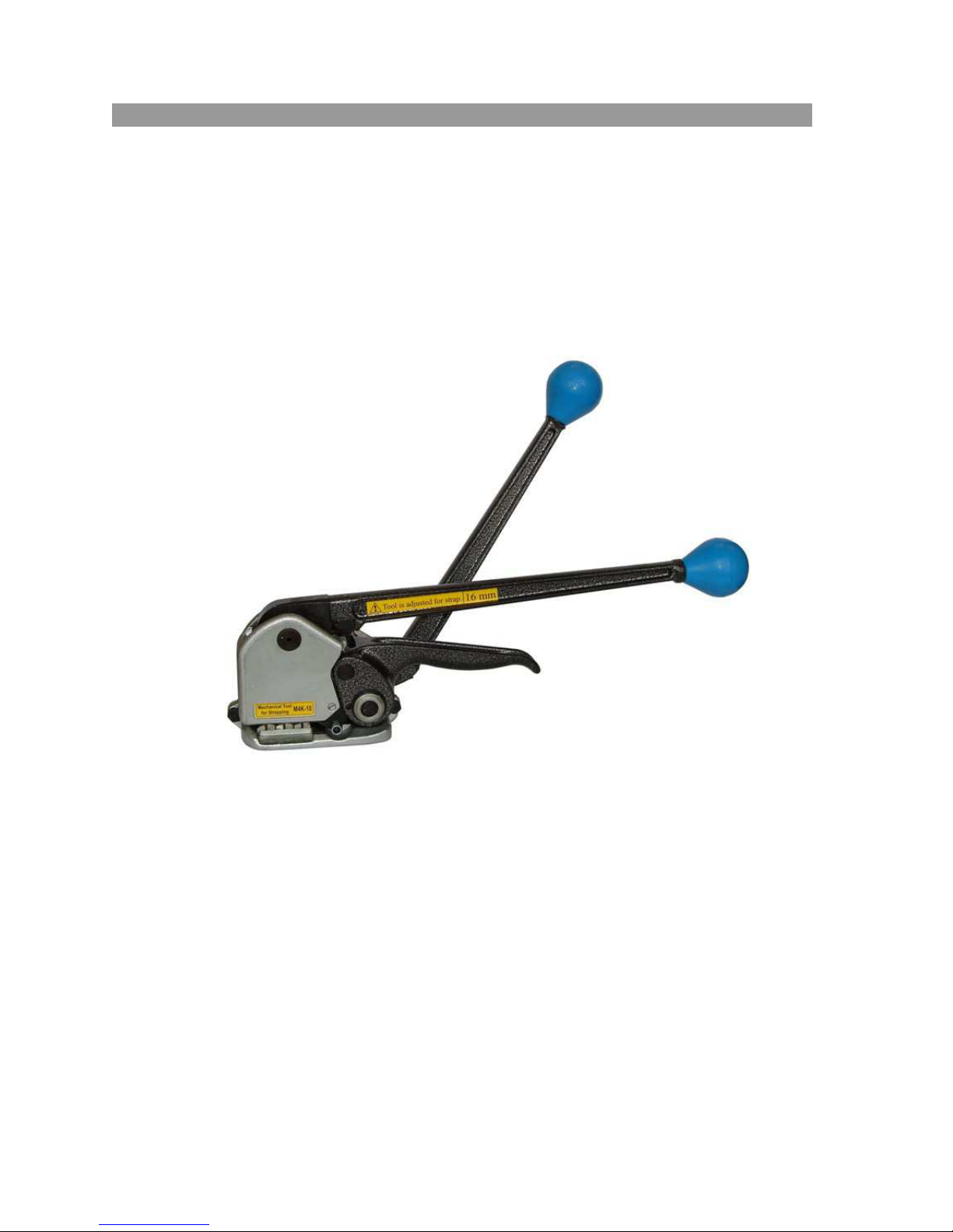
ENGLISH INSTRUCTIONS FOR REPAIR
MECHANICAL TOOL SOR STEEL STRAPPING
M4K-10 (MK4-10)
INSTRUCTIONS FOR REPAIR
2011
Page 2

Content
1. Introduction...........................................................................................3
Scheme of tension unit..........................................................................4
Scheme of cutting unit..........................................................................5
Table......................................................................................................6
2. Disassembly of tool...............................................................................7
2.1. Removal of parts with direct access.................................................7
2.2. Separation of tension and cutting units............................................11
2.3. Disassembly of tension unit.............................................................13
2.4. Disassembly of cutting unit.............................................................17
3. Assembly of tool...................................................................................21
3.1. Assembly of cutting unit..................................................................21
3.2. Assembly of tension unit.................................................................22
3.3. Connecting of tension and cutting units...........................................22
3.4. Installation of details with direct access..........................................23
2
Page 3

1. Introduction
1.1. This instruction defines the order of disassembly and assembly of the tool M4K-10
(MK4-10), during which some spare part can be changed.
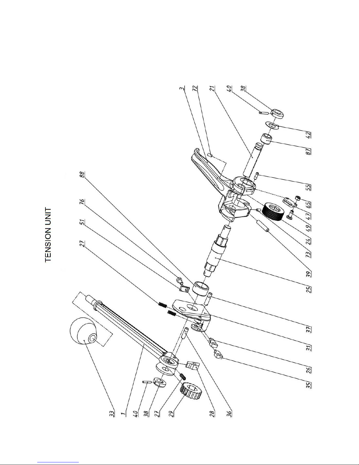
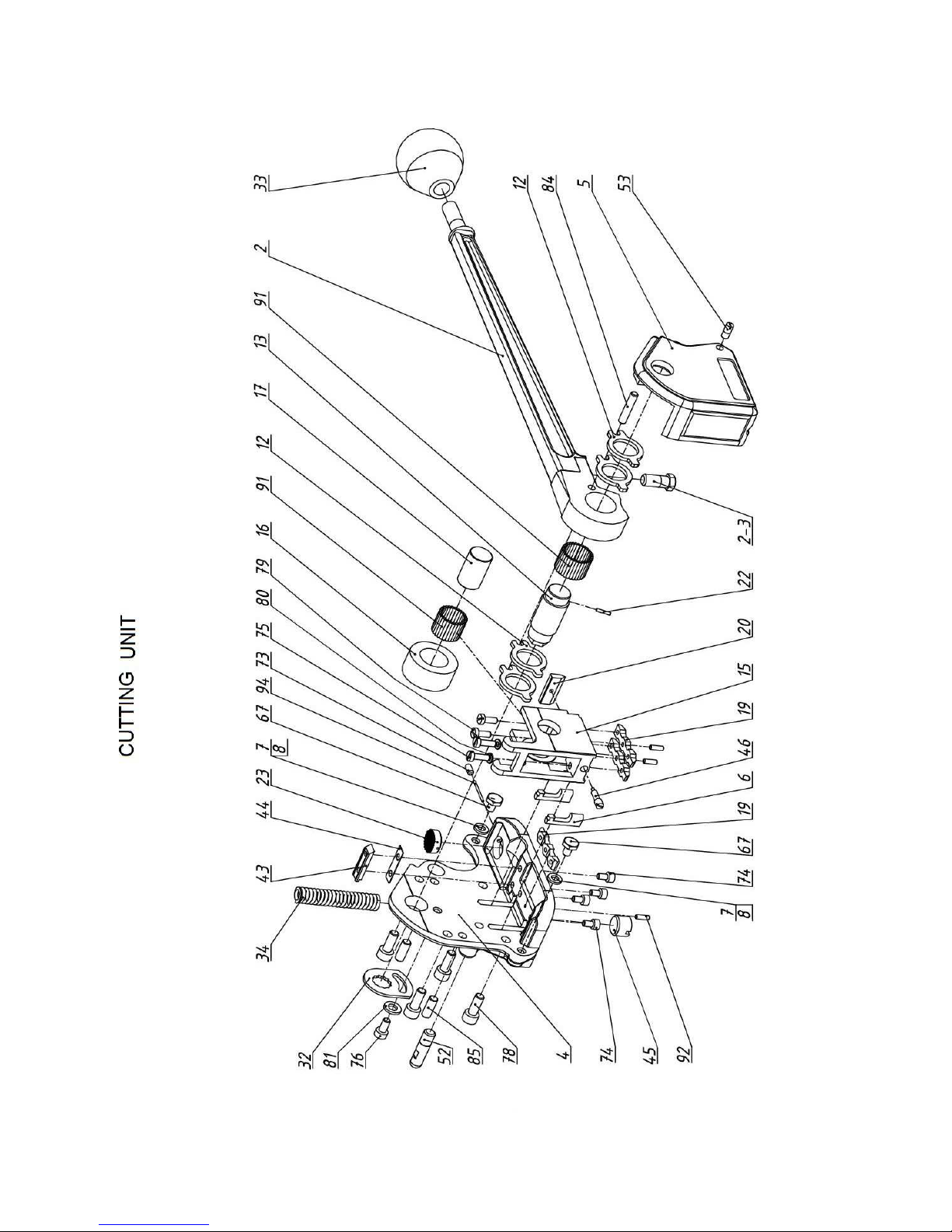
1.2. Numbers of spare parts and their location are shown in schemes of tension and
cutting units, from which the tool consists.
1.3. Full list of spare parts of tool and paragraphs of instruction, where it is shown how
to change needed spare part, are shown in table.
If paragraph is not shown in table, it means that replacement of part can be made
using only schemes of tension and cutting units.
1.4. After disassembly and assembly of tool it is needed to perform regulating of it in
accordance with operating instructions.
3
Page 4
4
Page 5
5
Page 6

Table
Name of spare part Pos. No. No. of points in instruction
Tension handle 1 2.3.4, 2.3.6, 2.3.7
Sealer handle 2 2.2, 2.4.1…2.4.3
Feedwheel support handle 3 2.2, 2.3.1…2.3.3, 2.3.9, 2.3.10
Frame 4 2.2, 2.4.1…2.4.2, 2.4.4, 2.4.5
Side cover 5 2.2, 2.4.1
Strap lifter 6 2.2, 2.4.1, 2.4.2, 2.4.4, 2.4.5
Washer 7 2.1.5
Washer 8 2.1.5
Washer 12 2.2, 2.4.1…2.4.3
Excentric shaft 13 2.2, 2.4.1…2.4.3
Die holder 15 2.2, 2.4.1, 2.4.2, 2.4.4, 2.4.6, 2.4.7
Cam follower 16 2.2, 2.4.1, 2.4.2, 2.4.4, 2.4.6
Die holder shaft 17 2.2, 2.4.1, 2.4.2, 2.4.4, 2.4.6
Die 19 2.2, 2.4.1, 2.4.2, 2.4.4, 2.4.7, 2.4.8
Cutter blade 20 2.1.9
Feedwheel support shaft 21 2.2.4
Roll pin 22 2.2, 2.4.1…2.4.3
Clutch plug 23 2.1.10
Feedwheel 24 2.2, 2.3.1…2.3.3
Feedwheel shaft 25 2.2, 2.3.1…2.3.4, 2.3.6, 2.3.8
Tension pawl 26 2.3.5
Spring 27 2.3.5, 2.3.7
Tension pawl 28 2.3.7
Ratchet wheel 29 2.3.4, 2.3.6
Support plate 31 2.3.4, 2.3.5, 2.3.6
Adjustment plate 32 2.1.1
Knob 33 2.1.2
Spring 34 2.2.3
Tension pawl 35 2.3.5
Screw 36 2.3.7
Screw 37 2.3.5
Washer 38 2.3.1, 2.3.4
Screw М6х30 39 2.1.7
Pin 40 2.3.1, 2.3.4
Washer 42 2.3.1
Bush 43 2.1.8
Plate 44 2.1.8
Stopper 45 2.2.2
Screw 46 2.1.9
Guide arm 47 2.2, 2.3.10, 2.3.11
Screw 49 2.2, 2.3.10, 2.3.11
Strap guide 51 2.1.3
Strap guide 52 2.1.4
Screw 53 2.2.1
Screw 55 2.3.10
Screw 65 2.3.11
6
Page 7
Continuation of the table
Screw 67 2.1.5
Screw М4х10 72 2.2.4
Screw М4х6 73 Screw М4х8 74 Screw М4х12 75 Screw М5х10 76 Screw М6х16 78 Screw М4х10 79 Washer 6 82 Roll pin 5х25 84 2.2, 2.4.1…2.4.3
Roll pin 6х16 85 2.2, 2.4.1
Small bearing 87 2.2, 2.3.1…2.3.3, 2.3.9
Large bearing 88 2.2, 2.3.1…2.3.4, 2.3.6, 2.3.8
Support roller 2х15,8 91 2.2, 2.4.1…2.4.6
Roll pin 3х9,8 92 Retaining wire diam. 1.4 94 2.1.10
2. Disassembly of the tool
Disassembly of the tool provides removal of parts, to which you have direct access (see
point 2.1), separation of tension and cutting units(p. 2.2) and further disassembly of each
unit (p. 2.3, 2.4).
2.1. Removal of parts with direct access.
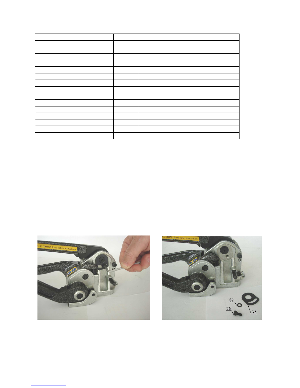
2.1.1. With the help of hex key S = 4mm unscrew the screw 76, remove washer 82 and
adjustment plate 32 (pic. 2.1.1, 2.1.2).
Pic. 2.1.1 Pic. 2.1.2
7
Page 8
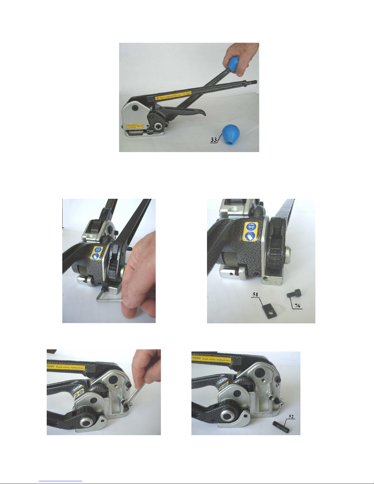
2.1.2. Unscrew knobs 33 (pic. 2.1.3).
Pic. 2.1.3
2.1.3. With the help of hex key S = 4mm unscrew the screw 76 and remove strap guide
51 (pic. 2.1.4, 2.1.5).
Pic. 2.1.4 Pic. 2.1.5
2.1.4. Unscrew with the help of wrench S = 6mm strap guide 52 (pic. 2.1.6, 2.1.7).
Pic. 2.1.6 Pic. 2.1.7
8
Page 9
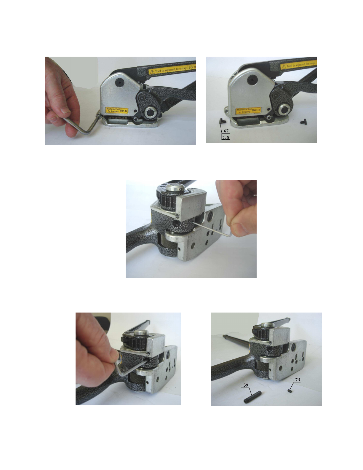
2.1.5. Unscrew with the help of socket wrench S = 10mm front and rear strap guides 67
(pic. 2.1.8, 2.1.9) with washers 7, 8.
Pic. 2.1.8 Pic. 2.1.9
2.1.6. Unscrew with the help of hex key S = 2mm screw 73 (pic. 2.1.10).
Pic. 2.1.10
2.1.7. With the help of hex key S = 3mm unscrew the screw 39 (pic. 2.1.11, 2.1.12).
Pic. 2.1.11 Pic. 2.1.12
9
Page 10

2.1.8. With the help of hex key S = 3mm unscrew screws 74, remove bush 43 and plates
44 (if available) (pic. 2.1.13, 2.1.14).
Pic. 2.1.13 Pic. 2.1.14
2.1.9. Turn sealer handle from yourself against the stop and with the help of hex key S =
2,5mm unscrew the screw 46 (pic. 2.1.15, 2.1.16). Return sealer handle to its original
position and with the help of tweezers remove cutter blade 20 (pic. 2.1.17).
Pic. 2.1.15 Pic. 2.1.16
Pic. 2.1.17
10
Page 11
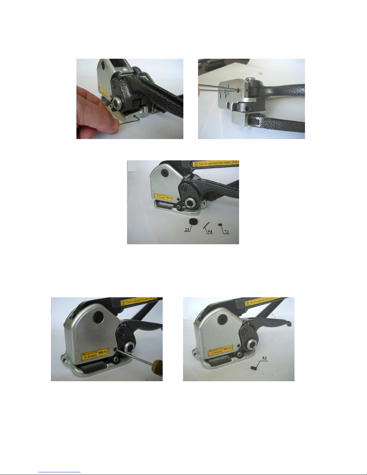
2.1.10. With the help of hex key S = 2mm unscrew the screw 73 from frame 4, remove
using tweezers retail wire 94 and remove clutch plug 23 (pic. 2.1.18 - 2.1.20).
Pic. 2.1.18 Pic. 2.1.19
Pic. 2.1.20
2.2. Separation of tension and cutting units.
2.2.1. Unscrew the screw 53 (pic. 2.2.1, 2.2.2).
pic. 2.2.1 pic. 2.2.2
11
Page 12
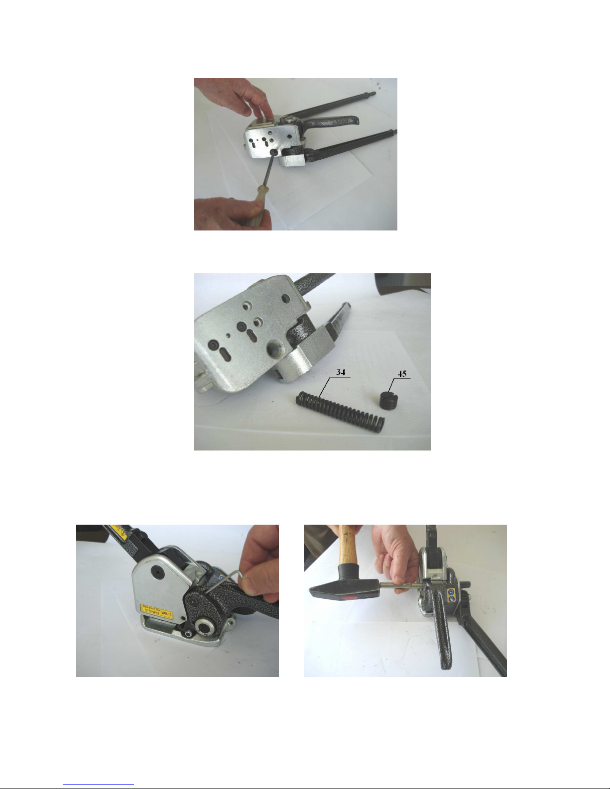
2.2.2. Unscrew stopper 45 from the foot of frame 4 (pic. 2.2.3).
Pic. 2.2.3
2.2.3. Remove spring 34 (pic. 2.2.4).
Pic. 2.2.4
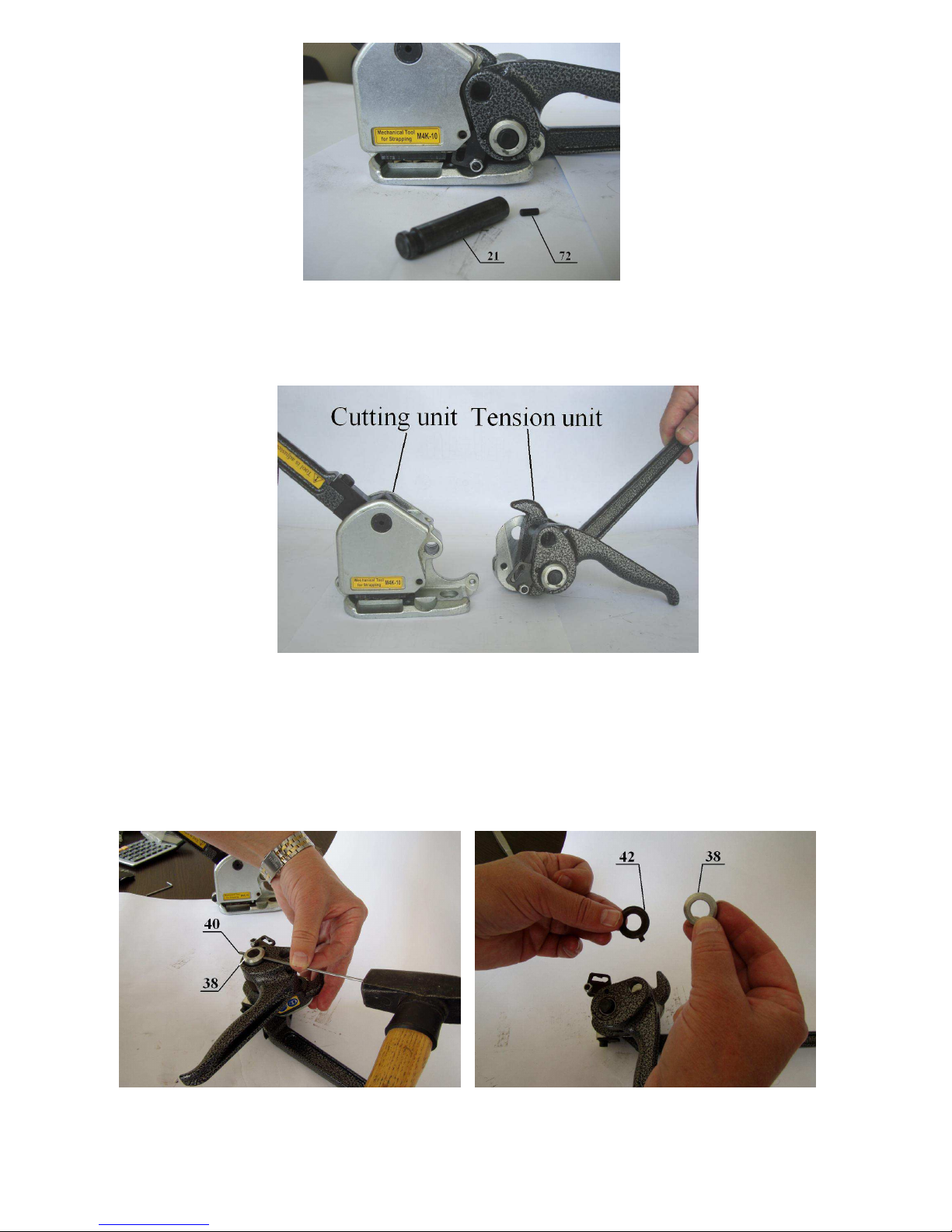
2.2.4. Unscrew with the help of hex key S = 2mm screw 72 and with the help of tapping
(ø10mm, length 120mm) knock out feedwheel support shaft 21 (pic. 2.2.5 - 2.2.7).
Pic. 2.2.5 Pic. 2.2.6
12
Page 13
Pic. 2.2.7
2.2.5. Disconnect tension unit from cutter unit (pic. 2.2.8).
Pic. 2.2.8
2.3. Disassembly of tension unit.
2.3.1. Knock out using tapping (ø2,5mm, length 100mm) pin 40, remove washer 38 and
washer 42 (pic. 2.3.1, 2.3.2).
Pic. 2.3.1 Pic. 2.3.2
13
Page 14

2.3.2. With the help of tapping (ø10mm) knock out feedwheel shaft 25 (pic. 2.3.3).
Pic. 2.3.3
2.3.3. Remove feed wheel 24 and remove handle 3 (pic. 2.3.4).
Pic. 2.3.4.
2.3.4. Knock out pin 40 and remove washer 38 (pic. 2.3.5).
Pic. 2.3.5.
14
Page 15
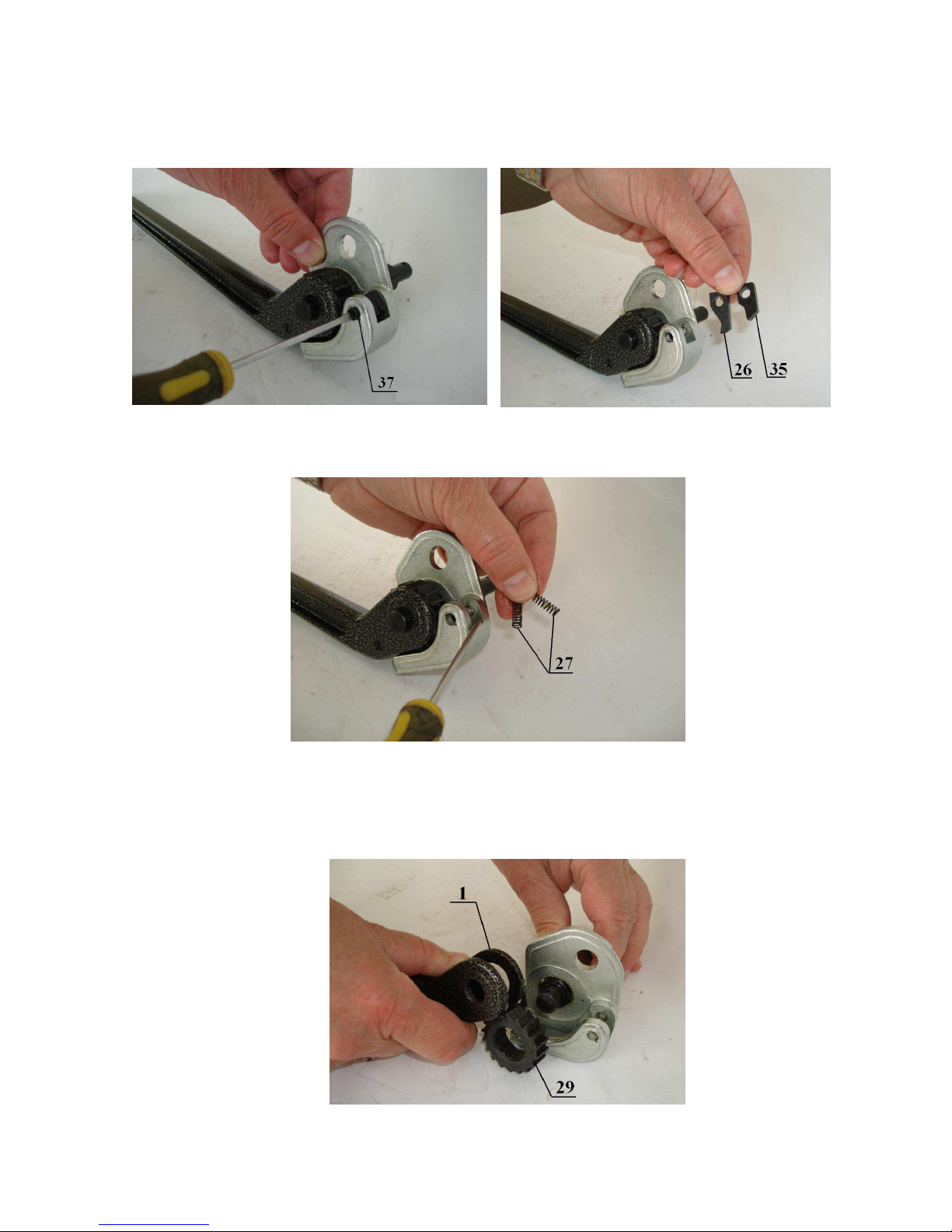
2.3.5. Unscrew tension pawl shaft 37 and remove tension pawls 26, 35 with 2 springs 27
from support plate 31 (pic. 2.3.6-2.3.8).
Pic. 2.3.6. Pic. 2.3.7.
Pic. 2.3.8.
2.3.6. Disconnect tension handle 1 with ratchet wheel 29 from support plate 31 remove
support plate from feedwheel shaft 25 (pic. 2.3.9).
Pic. 2.3.9.
15
Page 16
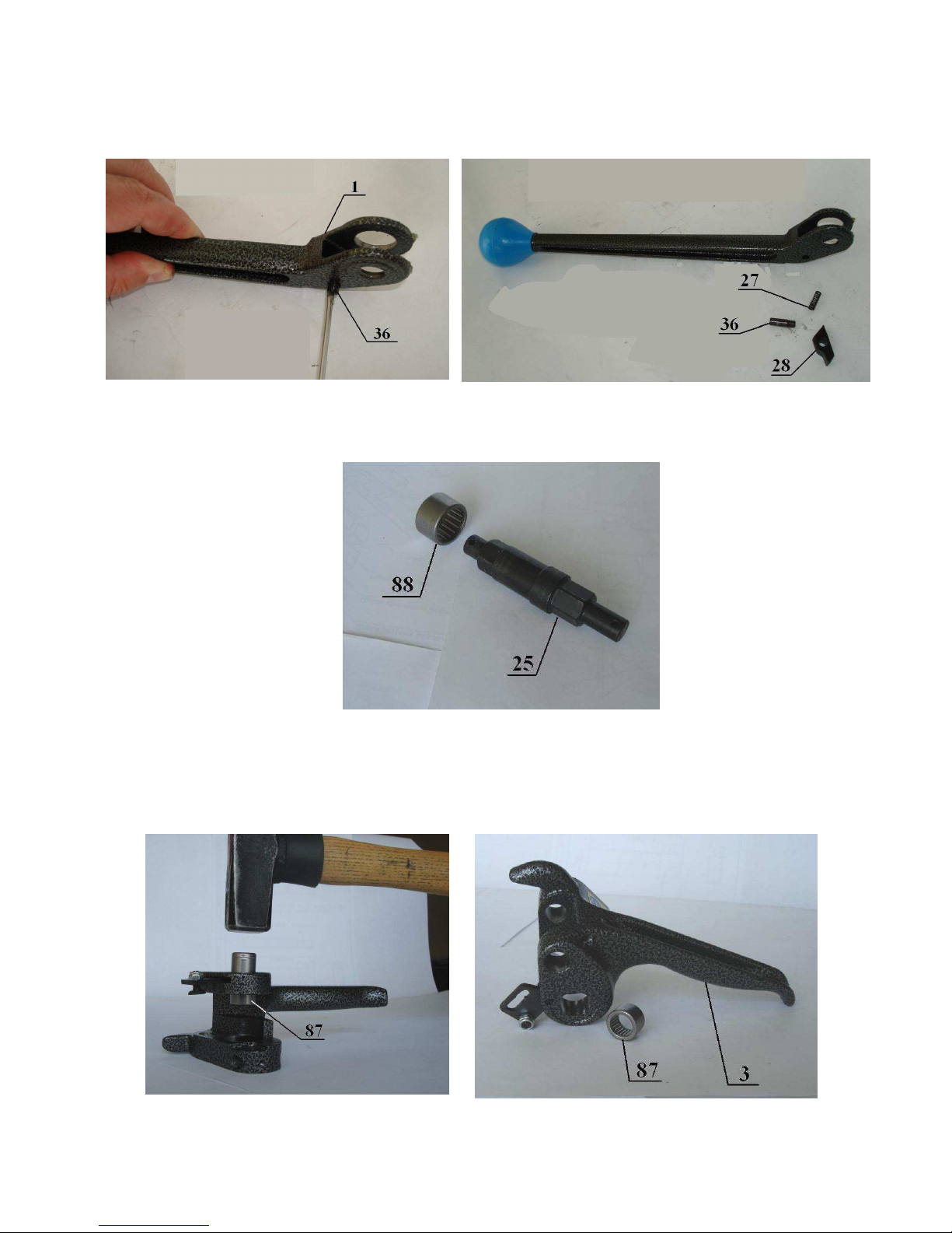
2.3.7. Unscrew the screw 36 from handle 1 and remove tension pawl 28 and spring 27
(pic. 2.3.10, 2.3.11).
Pic. 2.3.10. Pic. 2.3.11.
2.3.8. Remove bearing 88 from feedwheel shaft 25 (pic. 2.3.12).
Pic. 2.3.12.
2.3.9. With the help of tapping (ø16mm) knock out bearing 87 from handle 3 (pic.
2.3.13, 2.3.14).
Pic. 2.3.13. Pic. 2.3.14.
16
Page 17

2.3.10. Unscrew the screw 55 and remove guide arm 47 from handle 3 (pic. 2.3.15,
2.3.16).
Pic. 2.3.15. Pic. 2.3.16.
2.3.11. Unscrew the screw 65 and unscrew the screw 49 from guide arm 47 (Pic. 2.3.17,
2.3.18).
Pic. 2.3.17. Pic. 2.3.18.
2.4. Disassembly of cutting unit.
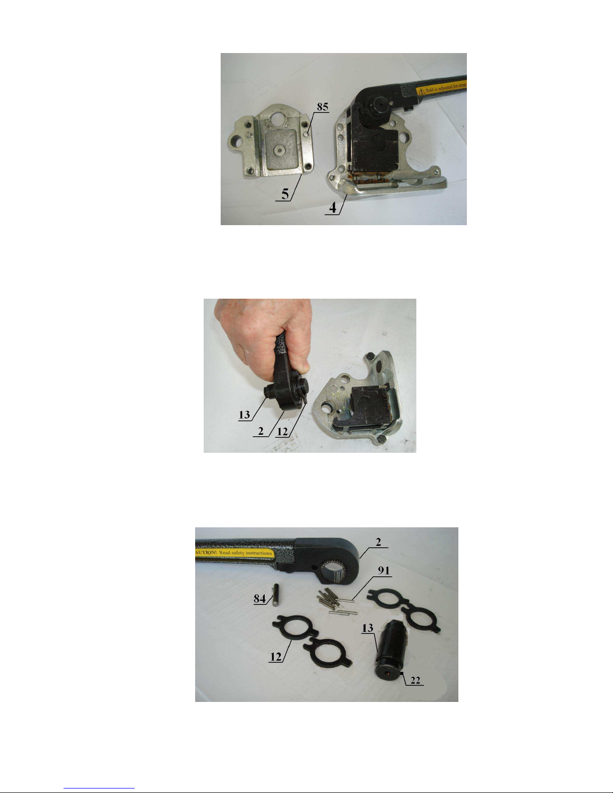
2.4.1. With the help of hex key S = 5mm unscrew four screws 78, disconnect side cover
5 from frame 4, using tapping (ø5mm) (pic. 2.4.1…2.4.3).
Pic. 2.4.1. Pic. 2.4.2.
17
Page 18
Pic. 2.4.3.
2.4.2. Remove sealer handle 2 in collecting with excentric shaft 13, washers 12 and set
of support rollers 91 (31pcs.) carefully, not to sprinkle rollers (pic. 2.4.4).
Pic. 2.4.4.
2.4.3. Disconnect four washers 12 from handle 2, remove excentric shaft 13 with roll pin
22, roll pin 84 and rollers 91 in quantity 31pcs. (pic. 2.4.5).
Pic. 2.4.5.
18
Page 19

2.4.4. Disconnect die holder 15 from frame 4 (pic. 2.4.6).
Pic. 2.4.6.
2.4.5. Remove strap lifters 6 from holes in frame 4 (pic. 2.4.7).
Pic. 2.4.7.
2.4.6. Remove die holder shaft 17, then remove from die holder 15 cam follower 16 and
rollers 91 in quantity 28pcs. (pic.2.4.8 - 2.4.10).
Pic. 2.4.8. Pic. 2.4.9.
19
Page 20

Pic. 2.4.10.
2.4.7. Using hex key S = 2,5mm remove screws 75 and 79 of fixing of dies 19 to die
holder 15 and remove dies from roll pin 92 (pic. 2.4.11).
Pic. 2.4.11.
2.4.8. With the help of hex key S = 3mm unscrew screws 74 of fixing of blade to frame
4. Remove blade from roll pin 92 (pic. 2.4.12, 2.4.13, 2.4.14).
Pic. 2.4.12.
20
Page 21
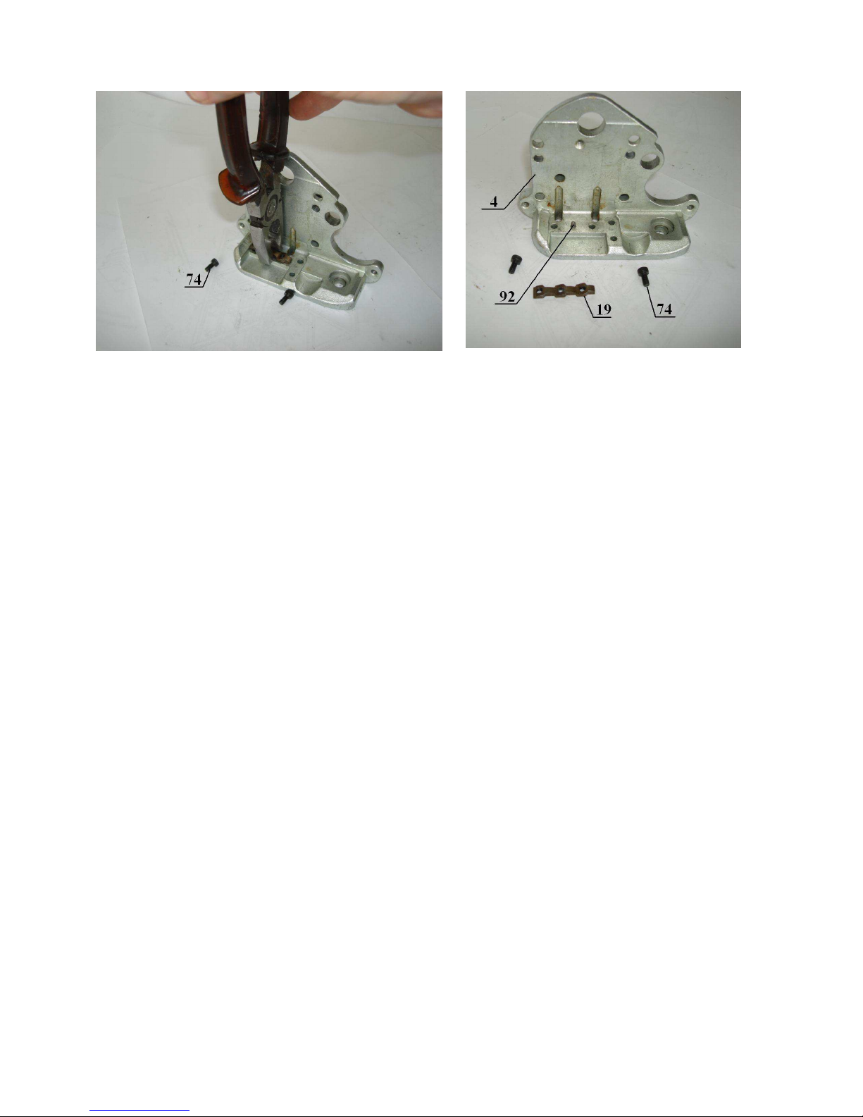
Pic. 2.4.13. Pic. 2.4.14.
3. Assembly of the tool
Assembly of the tool should be made in reverse order to its disassembly.
3.1. Assembly of cutting unit.
3.1.1. Set die 19 on roll pin 92 in frame 4 and tighten it lightly by screws 74 (see p.
2.4.8).
3.1.2. Set dies on roll pins 92 in die holder 15 and tighten them by screws 75, 79 (see. p.
2.4.7).
3.1.3. Insert in can follower 16 set of support rollers 91 in thick greasing. Set cam
follower 16 into die holder 15 and fix it by die holder shaft 17 (see p. 2.4.6).
3.1.4. Set strap lifters 6 in thick greasing into holes of frame 4 (see p.. 2.4.5).
3.1.5. Set die holder 15 on frame 4 in such way so strap lifters 6 stay into designated
holes in die holder 15 (see p. 2.4.4).
3.1.6. Set into handle 2 set of support rollers 91 in thick greasing, roll pin 84, excentric
shaft 13 with roll pin 22, and by 2 washers 12 from each side of handle (see p. 2.4.3).
3.1.7. Set carefully handle 2 in collecting with excentric shaft 13, roll pin 84 and support
rollers 91 into frame 4 (see p. 2.4.2).
3.1.8. Connect side cover 5 with frame for 4 so, they fit close to each other, and handle 2
should move free die holder 15. Screw four screws 78 (see p. 2.4.1).
21
Page 22

3.1.9. Turn sealer handle 2 from yourself and achieve, that dies 19, set in die holder,
easily passed die 19, set in frame 4, after that tighten the screws 74, fixing this die.
3.2. Assembly on tension unit.
3.2.1. Screw the screw 49 into guide arm 47 and fix it by washer 45 (see p. 2.3.11).
3.2.2. Set guide arm 47 with screw 49 and washer 45 into the groove of handle 3 and fix
it by screw 55 (see p. 2.3.10).
3.2.3. Knock in bearing 87 into handle 3 (see p. 2.3.9).
3.2.4. Set bearing 88 on feedwheel shaft 25 (see p. 2.3.8).
3.2.5. Set tension pawl 28 with spring 27 into handle 1 and fix it by screw 36 (see p.
2.3.7).
3.2.6. Connect weedwheel shaft 25 with support plate 31, handle 1 and ratchet wheel 29
(see p. 2.3.6).
3.2.7. Set into support plate 31 tension pawls 26, 35, springs 27 and fix them by screw
37 (see p. 2.3.5).
3.2.8. Set into feedwheel shaft 25, projecting from handle 1 washer 38 and fix it by pin
40 (see p. 2.3.4).
3.2.9. Set into feedwheel shaft 25 handle 3, feedwheel 24 and knock in it bearing 88 so,
support plate 31 tightly adjoined to handle 3, and the end of feedwheel shaft 25
performed from bearing 87 (see p. 2.3.2, 2.3.3).
3.2.10. Put on feedwheel shaft 25, performed from bearing 87, washer 42, washer 38
and fix it by pin 40 (see p. 2.3.1).
3.3. Connecting of tension and cutting units.
3.3.1. Connect tension and cutting units with the help of feedwheel support shaft 21, fix
it with pin 72 (see p. 2.2.4, 2.2.5).
3.3.2. Put in frame 4 spring 34 and screw stopper 45 (see p. 2.2.2, 2.2.3).
3.3.3. Fix guide arm 47 in side cover 5 by screw 53 (see p. 2.2.1).
22
Page 23

3.4. Setting of parts with direct access.
3.4.1. Set clutch plug 23 into frame 4 and fix it by retaining wire 94 and roll pin 73 (see
p. 2.1.10).
3.4.2. Set cutter blade 20 in the opening of side cover 5 and die holder 15 and fix it by
screw 46 (see p. 2.1.9).
3.4.5. Set bush 43 with plates 44 (if necessary) into frame 4 and fix them by screws 74
(see p. 2.1.8).
3.4.6. Screw the screw 39 into handle 3 (see p. 2.1.7).
3.4.7. Screw until stop screw 73 (see p. 2.1.6).
3.4.8. Screw front and rear guides 67 (see p. 2.1.5).
3.4.9. Screw guide 52 (see p. 2.1.4).
3.4.10. Set guide 51 in necessary position and fix it by screws 76 (see p. 2.1.3).
3.4.11. Screw knobs 33 into handles 1 and 2 (see p. 2.1.2).
3.4.12. Set adjustment plate 32 on excentric shaft 13 so, that the label on another side of
excentric shaft indicate «9 hours». Fix adjustment plate in such position by screw 76
with washer 82 (see p. 2.1.1).
Make regulation of assembled tool, using operating instructions.
23
Page 24

24
 Loading...