

Tenvis Mini319w, IP391, IP601, IP391W, IP602 User Manual
...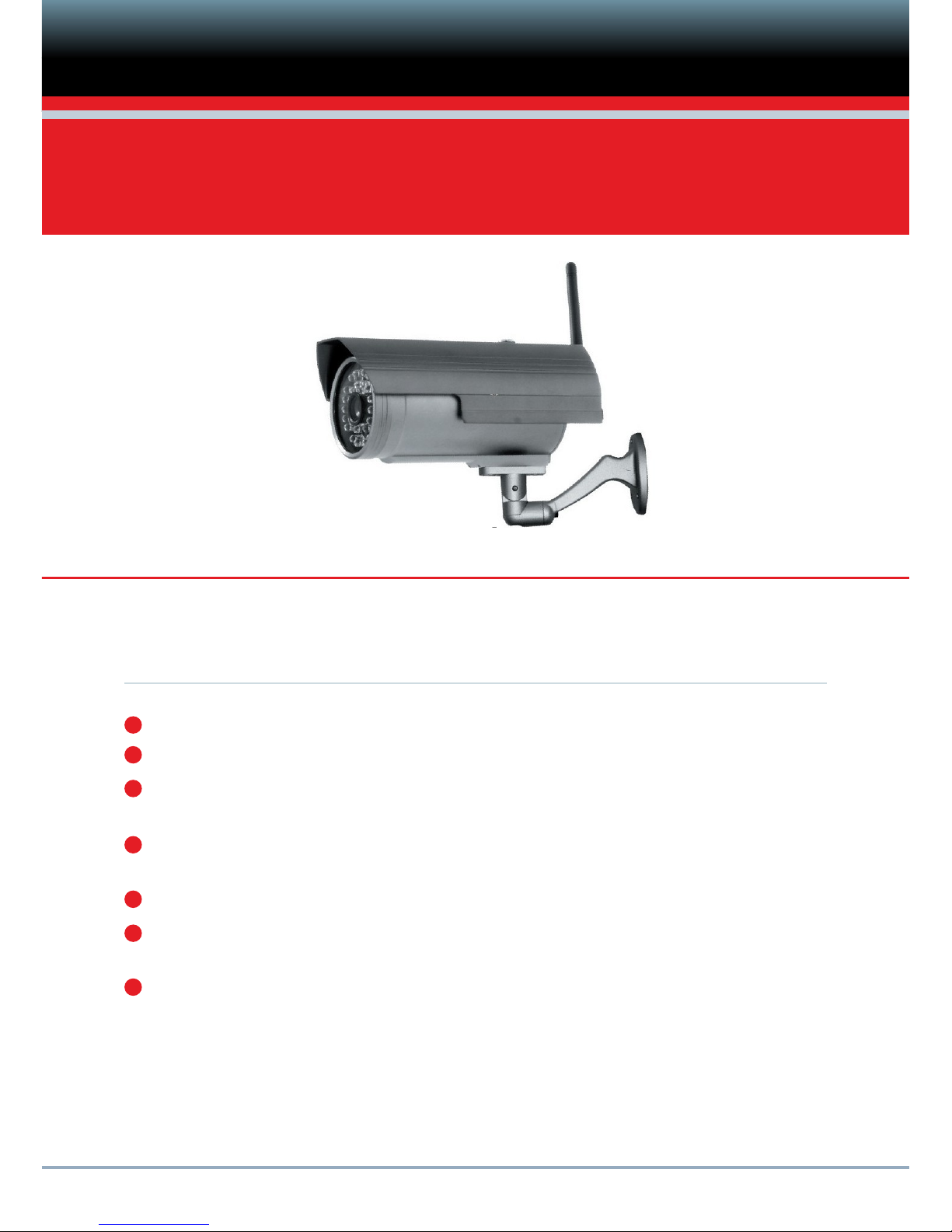
MJPEG SERIES OUTDOOR
WiFi outdoor IP Camera
BEFORE YOU BEGIN
Please unpack the box carefully and identify that all the parts are present.
The Camera is suitable for indoor or outdoor use.
Check the voltage of the power supply. Make sure you use the recommended power
input (12V DC, 1.0A). Use of incorrect voltage is not covered by the warranty.
Do not attempt to open the casing to access the Camera. Damage caused to the
product by tampering with the casing is not covered by the warranty.
Do not aim the camera at the sun or similar intense light.
The interval time of powering the camera on and off must be more than 10 seconds
otherwise it will cause serious damage to the CPU.
When you update the cameras, please ensure you:
- connect the camera directly to a computer using a network cable
- close other programs and windows on the computer
- keep the power connected when updating the firmware

PRODUCT DESCRIPTION
Camera combines a high quality digital
charge-coupled device (COMS) with a
powerful wireless web server for clear
images from anywhere on your local
network or over the internet.
Can be used on WiFi or Wired Networks.
Dual resolution, 640x480 or 320x240
pixel resolution.
Expand the system at any time by adding
up to 35 additional cameras.
View cameras in Split Screen view or
watch the camera detecting movement
full screen.
Cameras can be viewed via standard
PC or Mac browsers including Internet
Explorer, Safari, Chrome and Firefox.
IR LEDs for up to 20m Night Vision.
Cameras can be mounted indoors or
outdoors.
Includes Multi-level user management
which can be configured with secure
password access.
Easy to use web browser controls. Also
allows quick configuration changes via
the Settings menu.
View live images on your 3G Smartphone.
Supports image snapshots and image
sending via Email and FTP upload.
Supplied with free 36 Camera Windows
Recording and Viewing software.
FEATURES
NOTES ON WINDOWS AND MAC COMPATIBILITY:
- IP camera setup should be completed on a Windows PC only using Internet Explorer.
- Live viewing, taking snapshots, recording and camera configuration are fully supported on Windows
PCs.
Mac users are only able to:
- view live images via compatible web browsers including Safari, Firefox and Chrome but are
limited to viewing one camera at a time.
- take and save snapshot images via the web browser interface.
WiFi outdoor IP Camera can be set up in minutes for instant monitoring and live viewing on your
Mac or Windows computer and 3G Smartphone - all via your wireless network router or switch
For optional recording, simply install the Smart Witness recording software to you r Windows PC
and configure it to your particular requirements.
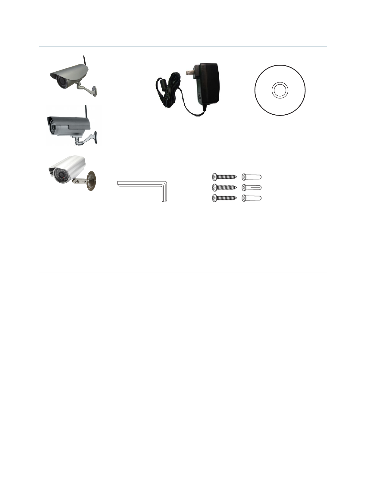
PACKAGE CONTENTS
Power Adaptor
Allen Key Screws and Wall Plugs
WiFi Camera with
Bracket & Antenna
Software
Installation CD
CAMERA INSTALLATION
1. Begin by screwing the antenna and bracket to the camera and power the camera using the power
supply provided.
2. Using a standard Ethernet network cable, connect the camera to your wireless network.
The camera can either be connected to a router/switch or directly to a PC with an Ethernet network
cable. We recommend you setup the camera initially on your network using a wired connection
before it is used wirelessly.
3. Continue with setup (read the next chapter) and once the camera has been successfully setup on
your network, it can be mounted on a wall using the wall plugs and screws provided. (Camera setup
is designed for Windows PCs only).

CAMERA SETUP continued
Please note that if you are using the camera on a wireless network you will need to
first configure the camera for wired use, before you programme your wireless settings
in to it.
1. Insert the Installation CD into your PC CD drive and the installation screen should appear
automatically. If it does not, click ‘Start > Run> Browse...’ to locate the CD on your computer .
2. Double click ‘IPCamSetup.exe’ and install the software as instructed.
3. Click Next, to complete the software installation.
The computer will restart upon completion of the installation and a new icon will appear on the
desktop automatically called ‘IP Camera Tool’.
4. Double click the icon to start the IP Camera Tool software. The software is designed to search the
Local Area Network (LAN) for any connected IP cameras or devices.
CAMERA SETUP continued
After searching, the software will give one of 3 results:
Connected IP cameras are located on the LAN - All the IP cameras will be listed and will be
displayed in the result field as shown below.
No IP Camera found within LAN - After about 1 minute search, the result field will show ‘Not
Found IP Server’ and the software application will shut down automatically.
The IP Cameras installed within LAN do not share the same subnet with the monitoring
PC. A prompt will be shown in result field ‘Subnet doesn’t match, double click to change!’ Double
click the mouse button and select ‘Network Configuration’ to set the IP address of the Camera to
the same subnet as LAN.
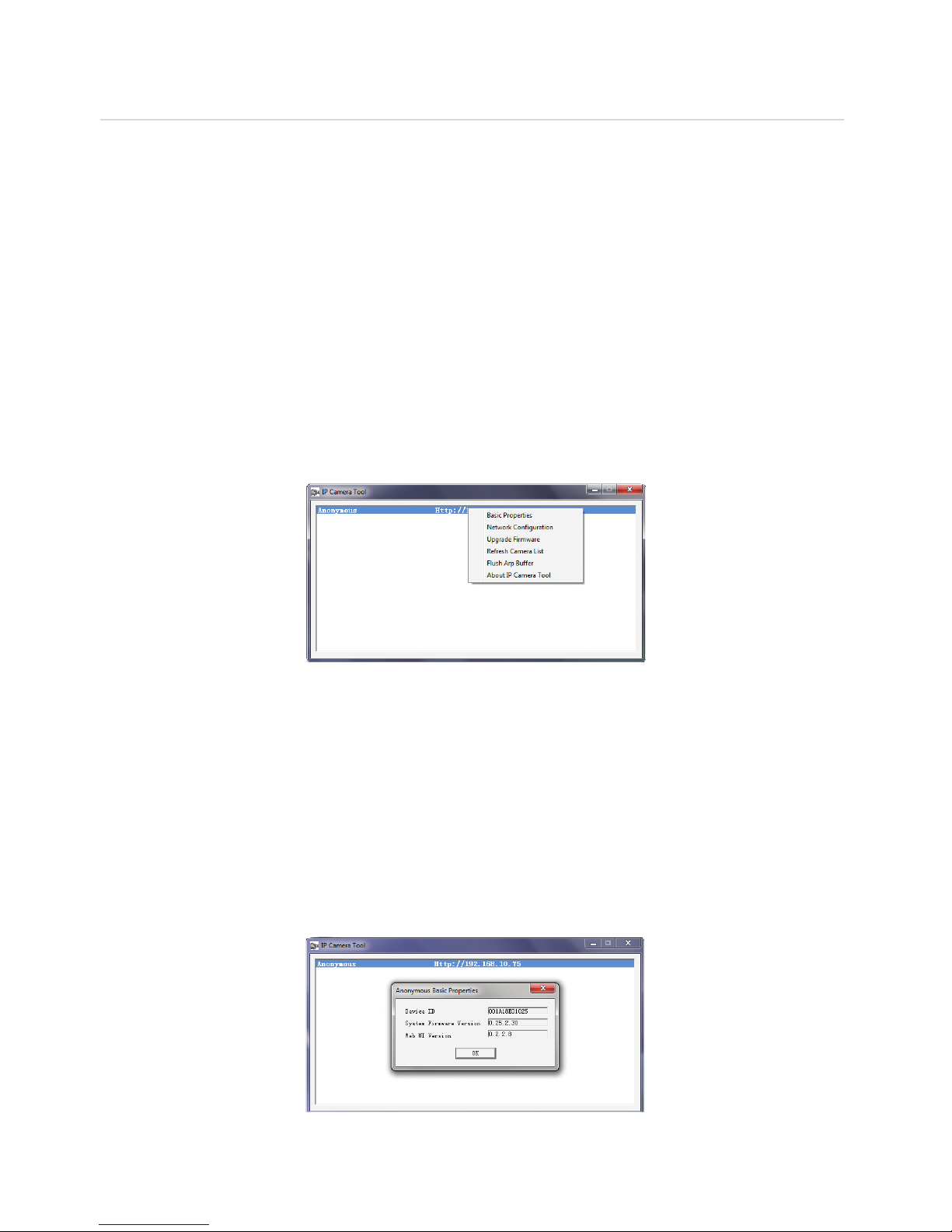
When you select an IP camera from the list and click the right mouse button, there are five options:
- Basic Properties
- Network Configuration
- Upgrade Firmware
- Refresh Camera List
- Flush Arp Buffer
Basic Properties
View device information such as Device ID, System Firmware Version, Web UI Version.
CAMERA SETUP continued
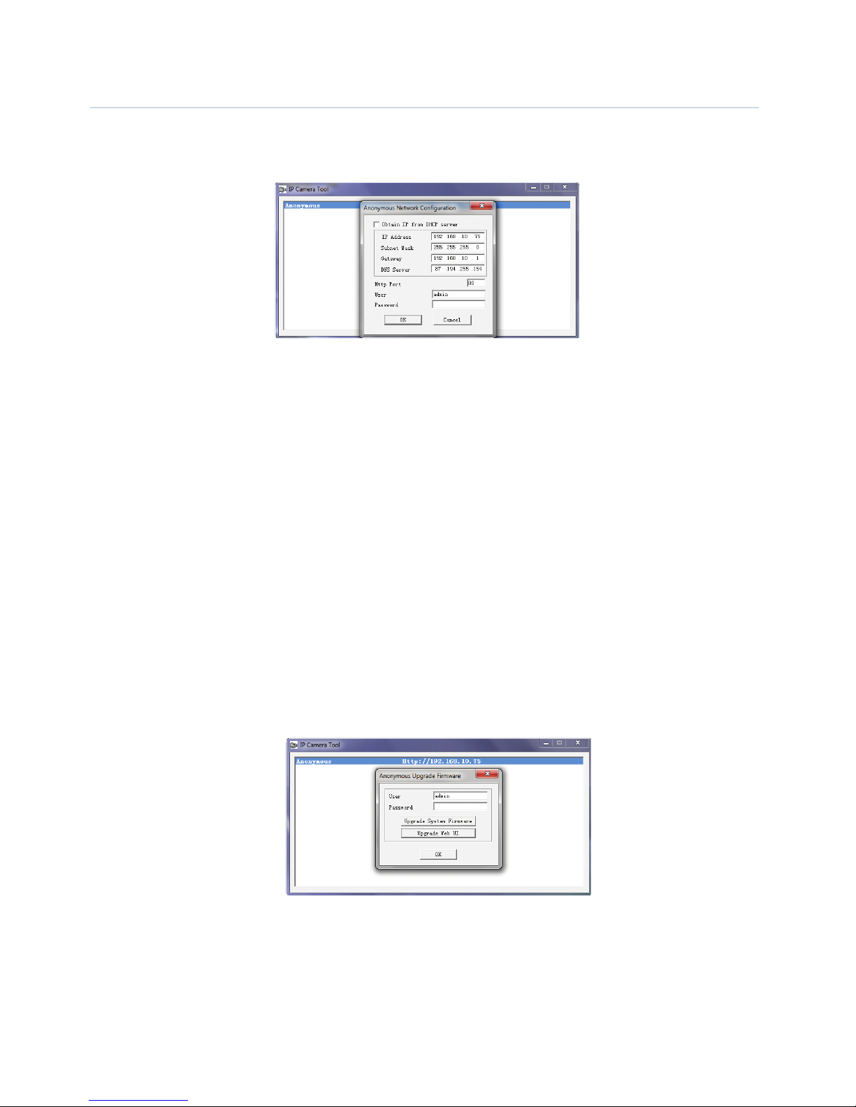
Network Configuration
Configure the Network parameters from this page.
• DHCP checkbox: If checked, the device will obtain an IP from the DHCP server (ensure the Router, with
which the device connects, has a DHCP function).
• IP address: Fill in the IP address assigned and make sure it is in the same subnet as the gateway (i.e. the
first three sections are the same).
• Mask: The default subnet mask of the equipment is: 255.255.255.0
• Gateway: Make sure it is in the same subnet with PC IP address. Default Gateway address is 192.168.0.1
• DNS: IP address of IPS network provider.
• Port: LAN port assigned for the equipment, usually 80.
• User & Password: (Default administrator User Name/Password = admin/No password).
If you enable using DHCP, the system will assign an IP address for your equipment only if your
gateway supports DHCP (which is the case with most gateways). NOTE: When the subnet doesn’t
match, double click to change it and set the camera’s IP address once again.
Upgrade Firmware
Enter the correct User Name and Password to upgrade the system Firmware and Web user interface.
Refresh Camera List
Refreshes the camera list manually.
CAMERA SETUP continued
Flush ARP Buffer
ARP stands for Address Resolution Protocol. It is used to associate a layer 3 (Network layer) address
(such as an IP address) with a layer 2 (Data Link layer) address (MAC address). When a wired
network and a wireless network of the camera both use the same fixed IP address, a problem may
occur where connections to web pages will time out and fail. Use the Flush ARP Buffer to clear the
ARP cache and fix the error.
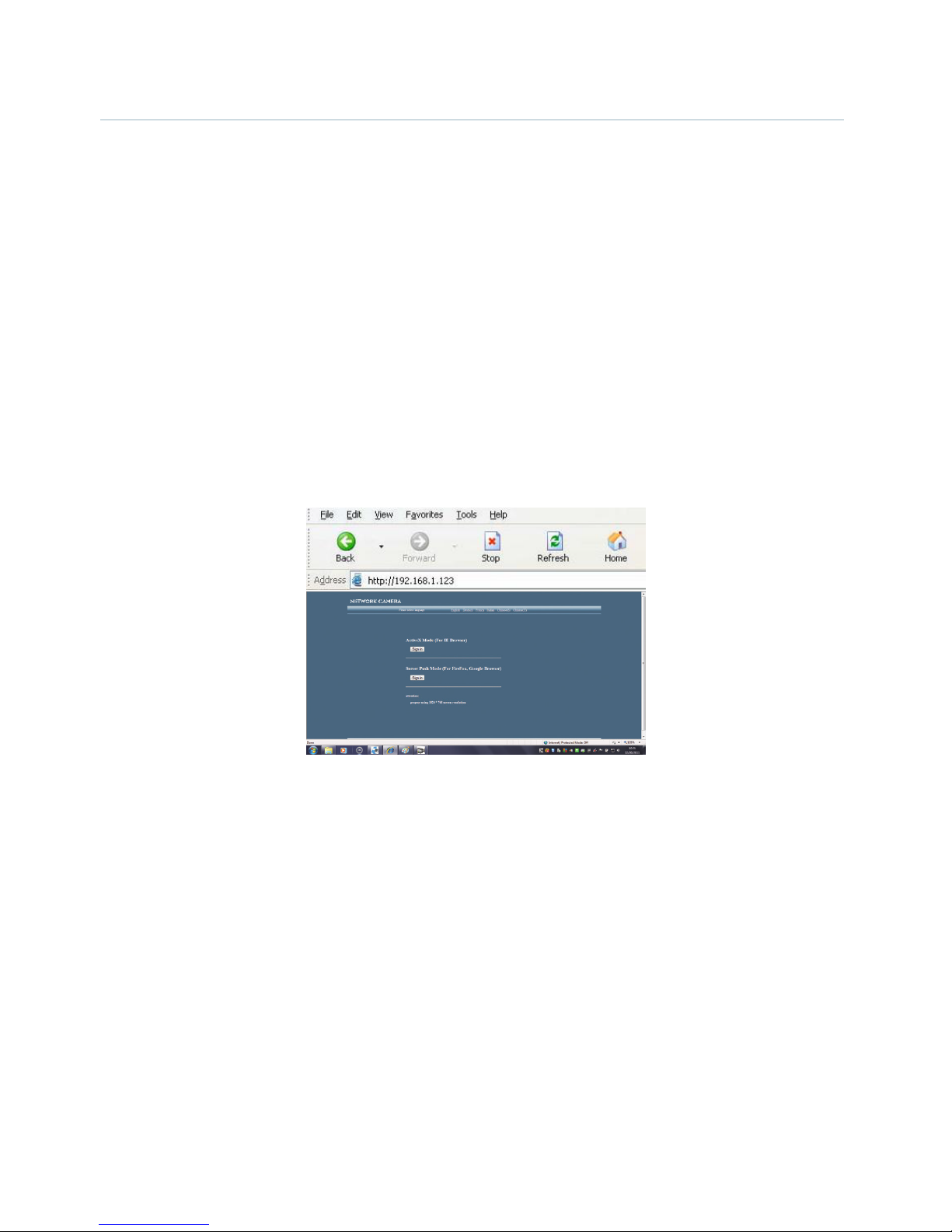
5. Access the IP camera through the IP Camera Tool or IE directly. Either:
• Double click the IP address of the IP camera listed in the search result window. Internet Explorer will be
opened automatically and display the camera login page.
Access the camera via the Internet Explorer browser directly by typing in the camera’s IP address. In the window
that appears, click the ‘
Sign in’ button as shown below:
6. The Camera Login page will pop up. Enter your account and password on the login page.
By default administrator’s username is: admin and no password. Click Sign in to enter the
monitoring page. You can enter the page as an Administrator, Operator or Visitor. Each type of user
will allow different levels of access on the web browser interface. Read below for more information
on the access rights and user interface.
Visitor: In this mode, you can only view.
Operator: You can control the image setting of IP Camera and set some parameters.
Administrator: You can setup the advanced configurations of the IP Camera.
7. If you are using a PC, follow the top link for IE Browsers. This will activate ActiveX which allows
access to additional functions of the user interface.
If you are a Mac user, you can view the camera via the second link, Server Push Mode. This web
browser mode features limited functionality but allows Live View and Image Snapshots.
CAMERA SETUP continued
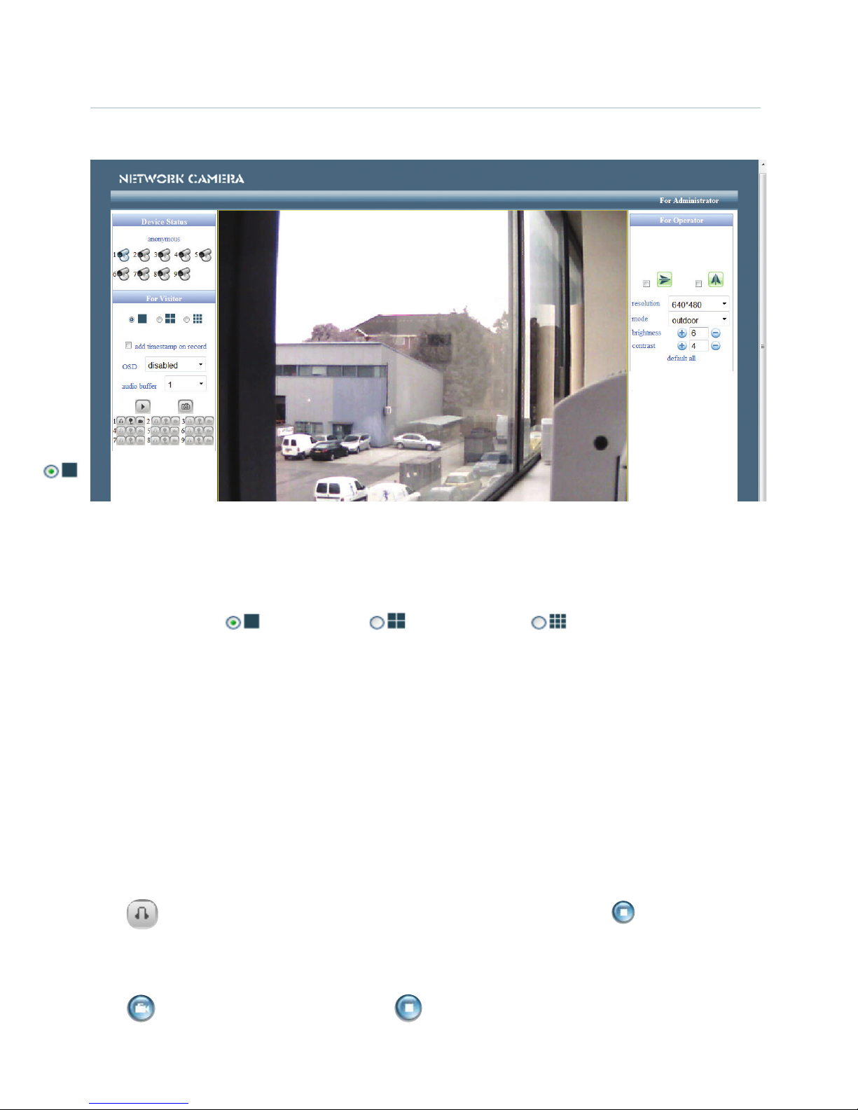
Main User Interface (as seen in Internet Explorer)
Device Status
Indicates the number of cameras connected on the network.
For Viewer
Allows you to view Full Screen or in Split Screen. Select the icons according to the view preferred.
For example: Select for Full Screen, for Quad view or for Multi Split Screen.
Add timestamp on record
When checked, a timestamp will be added in the bottom right corner of recorded videos.
OSD (On Screen Display) for Multi-Device Settings
Display the date and time on the video. You can disable the OSD function.
Audio buffer
Set the audio buffer time in sconds.
Audio switch
Click to enable the audio stream for the camera. The icon will change to . Click this to stop
the audio.
Record
Click
icon to go into Record mode. Click to stop. (Audio recording is active if audio is on).

CAMERA SETUP continued
Snapshot:
Click the icon to take a snapshot image.
Note
:
Recorded video file names will be saved in the format: CameraName_ Current time.
For example: IPCAM_20081211134442. This recording is from the camera called IPCAM and the
recording ‘end’ time was 13:44:42 on December 11, 2008.
For operator
When you login as an Operator or Administrator, you can enter the ‘For Operator’ page.
Mirror
Click the icons to see the horizontal or vertical mirror image.
Resolution
Select either VGA (640x480) or QVGA (320x240).
Work mode
Select either 50Hz, 60Hz or Outdoor.
Brightness and Contrast parameters
Click the + or - icons to adjust the brightness and contrast of the camera image.
Default All
Click to return the settings to the factory defaults.
For Administrator
When you login as an Administrator, the ‘For Administrator’ functions are enabled.
Device Info - You can find information about the camera such as the Device ID, Firmware Version
and Embeded Web UI Version.
Alias Settings - You can change the name of the IP camera.
Data & Time Settings - Set the time and date.
CAMERA SETUP continued
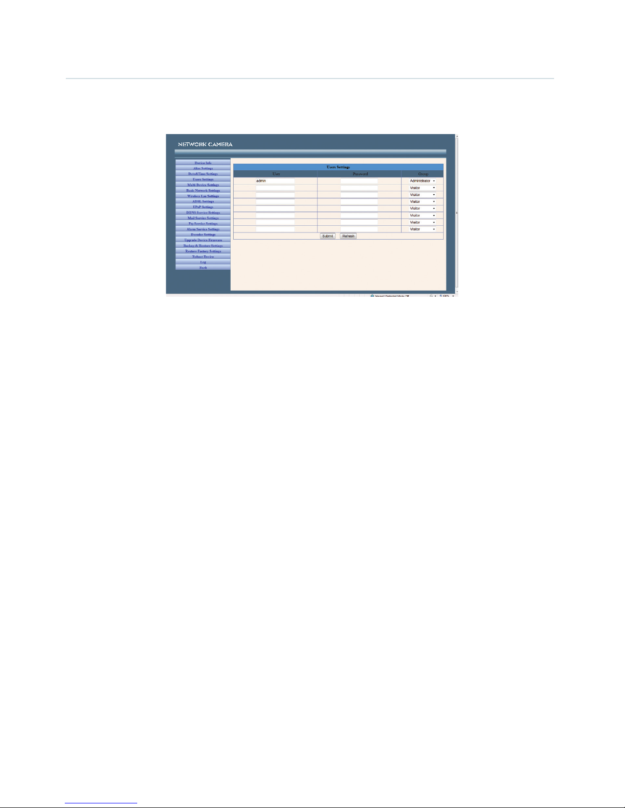
User Settings - You can configure up to 8 user names and passwords and the level of users as
Administrator, Operator or Visitor.
Administrators can:
Set Record Path - Click ‘Browse’ to choose the recording path of where video files will be saved.
Set Alarm Record Path - Click ‘Browse’ to choose the alarm recording path.
Note:
1. The default path for saving files is C:\Documents and Settings\All Users\Documents.
2. In Windows Vista, there are two points you need to notice:
• Vista’s Security level is higher than Windows XP/2000. For the ‘Set Record Path’ function, you will need to
add the add the Device IP address to IE’s ‘Trusted sites’ first. To do this go to: Tools > Internet Properties >
Security >Trusted sites > Sites > Add. In Vista, there is a prompt to add Trusted sites when the Set Record/
Alarm Record path is clicked.
• You cannot set the Windows System Root Directory as you will do for the Record/Alarm Record Path. This
prompt only pops-up in Vista.
UPnP Settings - Access this page to make sure the UPnP Status is working.
Upgrade Device Firmware - Upgrade the camera’s Firmware and device embeded web UI software on
this page.
Restore Factory Settings - Restore factory settings of the device.
Reboot Device - Reboot the device.
 Loading...