

Page 1
Bi‐DirectionalWirelessIRRepeaterSystemUserGuide
USB powered Wireless IR Repeater Dongle
A-1410K
Ten-Tronics
PRODUCT FEATURES:
1. It works not only as a IR Repeater but also works as a wireless IR Extender
2. Radio Frequency (RF): 915 MHz
3. RF working Range up to 100+ meters in Open Space.
4. IR carrier tuning freq.: 20~ 60KHz
5. Compliant with CE/FCC EMC regulation
6. High receiving sensitivity (-90dBm).
7. Bi-Directional full band IR Control
8. Channel Pairing.
SPECIFICATIONS
IR:
1. Compatible with all Universal full band carrier frequency infrared Remote (20KHz to 60KHz)
2. Better IR receive sensitivity (distance), over 7 meters
RF:
1. Long range RF transmission over 100+ meter in open space
2. Use 915MHz RF technology to avoid interference in crowded 433MHz RF activities
3. Bi-Directional full band IR Control
4. FSK modulation:
Better signal sensitivity than ASK modulation
Better Anti RF-interference than ASK modulation
Better performance in noise suppression
5. Digital data encryption function ensures safety and reliability
6. Support:
One receiver to one transmitter. (Point to Point)
One receiver to multi transmitters, (Point to Group)
Multi receivers to one transmitter. (Group to Point)
Multi receivers to multi transmitters. (Group to Group)
7. Channel Pairing/ Channel addressable grouping
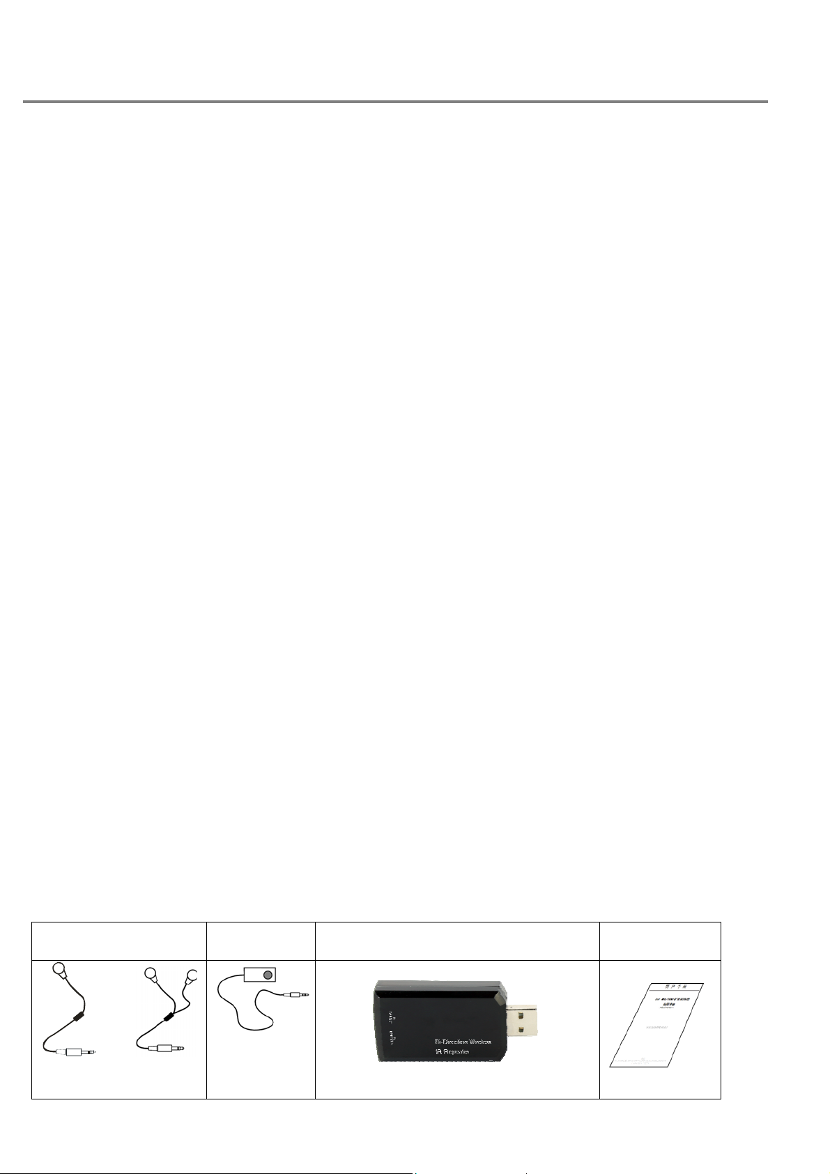
Kits Includes:
IR Emitter cable IR Target cable 2x Bi-Directional Wireless USB IR Dongle User manual
or
Single Dual
Page 2
Bi‐DirectionalWirelessIRRepeaterSystemUserGuide
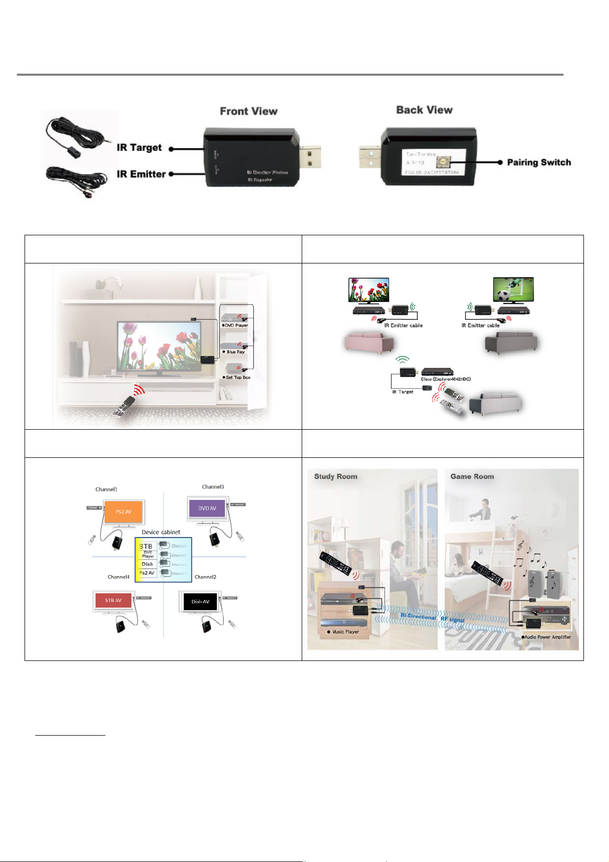
Applications
IR Repeater Broadcasting Control
Addressable Control Bi-Directional Control
Installation steps:
Application1: Single dongle IR Repeater (without RF)
Step1: Connect with the power
Place the dongle (one piece of wireless USB IR Dongle) on the USB power adaptor.
OR place the dongle (wireless USB IR Dongle) to the USB jack in back of an home equipment
(TV, CD, etc.).
Step2: Connect the cables
Page 3

Bi‐DirectionalWirelessIRRepeaterSystemUserGuide
Plug-in the IR target cable to the “IR TARGET” of the dongle that receive IR signals from the
Remote Control.
Plug-in the IR emitter cable to the “IR EMITTER” of the dongle that is near the devices you
want to control
Step3. Adjust the IR T ARGET and IR EMITTER
Place the “IR TARGET CABLE” at your desired location, near the devices you want to control
Aim the IR EMITTER EYE on each device (IR RECEIVER EYE) you want to control
Step4: Have fun with the wireless IR control
Power on and enjoy.
Application2: Wireless IR Broadcast Control
Step1: Connect dongles with the USB power
Place the dongles. One dongle at local side (in the same room as the Remote Control) and the
other dongles at Clint sides (near the devices you want to control. Multiple dongles for multiple
room). Connect the dongles with USB power adaptors, or insert the dongle (wireless USB IR
Dongle) to the USB jack in the back of a device.
Step2: Connect the cables
Plug-in the IR target cable to the “IR TARGET” of the dongle that receive IR signals from the
Remote Control.
For each dongle at a client site, plug-in the IR emitter cables to the “IR EMITTER” of the
dongle that is near the devices you want to control
Step3. Adjust the IR T ARGET and IR EMITTER
Place the “IR TARGET CABLE” so that it can be directly aimed with the Remote Control.
Place the “IR EMITTER CABLE” on the devices you want to control
Aim the IR EMITTER EYE on each device (IR RECEIVER EYE) you want to control
Step4: Make sure all dongles use the same RF channel. Use the Pairing switch to select RF
channel
if necessary.
Step5: Have fun with the wireless IR control
Power on and enjoy.
[NOTE: Due to IR code characteristics, multiple Remote Controls with different brand can be used
for this setup to control its target devices in different room.]
Application3: Addressable Control (multiple channels for multiple groups)
Step1: Connecting with the power
Place the dongle at local side in the same room as the Remote Controls. Use as many
Page 4

Bi‐DirectionalWirelessIRRepeaterSystemUserGuide
dongles as how many groups that are needed for setup. They may not be in the same room.
Place the other dongles at Clint sides, near the devices you want to control. Multiple dongles
for multiple rooms. Connect the dongles with USB power adaptors, or insert the dongle
(wireless USB IR Dongle) to the USB jack in the back of a device.
Step2: Connecting the cables
Plug-in the IR target cable to the “IR TARGET” of the dongle that receive IR signals from the
Remote Control.
Plug-in the IR emitter cables to the “IR EMITTER” of the dongle that is near the devices you
want to control
Step3. Adjustment the IR TARGET and IR EMITTER
Place the “IR TARGET CABLE” so that it can be directly aimed with the Remote Control.
Place the “IR EMITTER CABLE” on the devices you want to control
Aim the IR EMITTER EYE on each device (IR RECEIVER EYE) you want to control
Step4: Adjust the Pairing switch
Based on your grouping idea, adjust all Pairing switch on the dongles you want to control. Both
at the device sides and the Remote Control sides.
Step5: Have fun with the wireless IR control
Power on and enjoy.
Application4: Bi-Directional Control
Step1: Connecting with the power
Place the dongles in two rooms. Each room may have an equipment to be controlled from the
other room and a Remote Control to control a target equipment in the other room. Connect the
dongles with USB power adaptors, or insert dongle (wireless USB IR Dongle) to USB jack in
the back of a devices.
Step2: Connecting the cables
For each dongle in each room, plug-in the IR target cable to the “IR TARGET” and IR emitter
cables to the “IR EMITTER”.
Step3. Adjustment the IR TARGET and IR EMITTER
Place the “IR TARGET CABLE” so that it can be directly aimed with the Remote Control.
Place the “IR EMITTER CABLE” on the devices you want to control
Aim the IR EMITTER EYE on each device (IR RECEIVER EYE) you want to control
Step4: Adjust the Pairing switch
Adjust all Pairing switch and make sure both IR Wireless Repeater dongles are set to the
same channel.
Step5: Now the dongle can forward the Remote Control signal to the other room and send IR
Page 5

Bi‐DirectionalWirelessIRRepeaterSystemUserGuide
signals that is
received via the RF from the other room. Power on and enjoy.
Trouble Shooting
Case Phenomena Description Trouble shoot
1 The distance between remote control and
IR Receiver is short (perhaps less than 5
Meters)
2 Target device does not work with your IR
Kit
3 I have connected the way as the user
manual said, but still cannot get this kit to
work.
Please make sure the battery in the remote
control is sufficient. (Because the working
distance between IR Receiver and remote
control is determined by the IR signal power of
your remote controller.
Try to replace the old battery with the new battery
in your remote controller.
Usually, this kit should work perfectly across
various brand of remote controller. In rare case, if
you encounter this problem, please report the
model number for your device to us. Customer
service will take care of you.
Please check the material of your cabinet.
If your cabinet is made by metal, Radio
Frequency may not pass through. We
recommend to relocate our device outside of the
4 In manual, it said it can work “within or
over 100 meters open space”, but why it
may just work 50 Meters for me.
cabinet, and make sure Radio Frequency can
function as the product is designed.
“Open space” means there’s nothing between “IR
Receiver” and “IR Emitter”. So, for the RF
distance between “IR Receiving unit” and “IR
Emitter unit” could be reduced by wall, cabinet,
furniture, etc.
Page 6

Bi‐DirectionalWirelessIRRepeaterSystemUserGuide
Federal Communication Commission Interference Statement
This equipment has been tested and found to comply with the limits for a
Class B digital device, pursuant to Part 15 of the FCC Rules. These limits
are designed to provide reasonable protection against harmful interference
in a residential installation. This equipment generates, uses and can
radiate radio frequency energy and, if not installed and used in accordance
with the instructions, may cause harmful interference to radio
communications. However, there is no guarantee that interference will not
occur in a particular installation. If this equipment does cause harmful
interference to radio or television reception, which can be determined by
turning the equipment off and on, the user is encouraged to try to correct the
interference by one or more of the following measures:
Reorient or relocate the receiving antenna.
Increase the separation between the equipment and receiver.
Connect the equipment into an outlet on a circuit different from thatto
which the receiver is connected.
Consult the dealer or an experienced radio/TV technician for help.
FCC Caution: Any changes or modifications not expressly approved by the
party responsible for compliance could void the user's authority to operate
this equipment.
This device complies with Part 15 of the FCC Rules. Operation is subject to
the following two conditions: (1) This device may not cause harmful
interference, and (2) this device must accept any interference received,
including interference that may cause undesired operation.
This device and its antenna(s) must not be co-located or operating in
conjunction with any other antenna or transmitter.
 Loading...