

Tentative 59001, 59002, 59005 Installation And Operation Manual
REVOLUTION DCC SYSTEM
INSTALLATION AND
OPERATION MANUAL
TENTATIVE
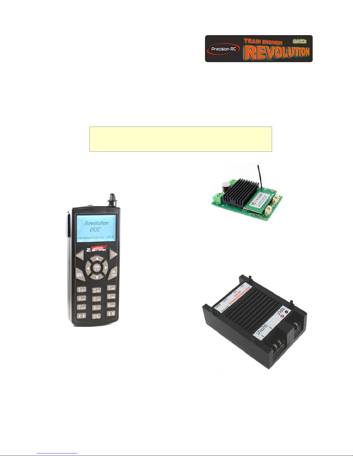
DCC 5A Command / Booster Station /Mobile
Receiver
#59002
Revolution DCC Transmitter 'TX'
#59001
2.4GHz DCC R/C System <TENTATIVE> 1
15 AMP Station Command/Booster RX
#59005

1 INTRODUCTION:
Congratulations on your purchase of the Revolution DCC wireless system.
The Revolution-DCC system can be used with any existing NMRA compliance standard decoders. This system
is very easy to use because it does not connect to any wire to the command station. It works with IEEE-801.15.4
standard 2.4GHz DSSS radio frequency band for ultimate stability and interference free operation even with the
same frequency channel.
Unlike conventional DCC products, you do not have to remember the complex DCC address of the Locomotive
or Accessory numbers. You only need to select the CAB # or ACEES CONT # whose Loco or Accessory name
and the DCC address number will be displayed on the TX main LCD screen. The DCC program to the decoder is
very simple, and it is also very convenient because you can read the CV data or DCC address value from the
decoder.
The locomotive and accessory profile data can be stored and recalled up to 2,500 profiles.
Since multiple transmitters can be used on the same layout, they can be used simultaneously with the other
members.
2 OPERATION OVERVIEW:
The Revolution DCC system lets you walk around your model railroad layout and remotely control your
DCC decoder equipped locomotive and DCC accessory such as switch turnouts. Before you start working with
the Revolution DCC System, there are a few concepts that you need to understand about the PROFILE NUM
[1-25]. Each profile number contains all the locomotive or accessory DCC data information to connect the DCC
decoders. Our Transmitter and Receiver are designed to communicate to the DCC decoder in your locomotives
or accessories.
The first concept is to establish a control between the transmitter, receiver and DCC decoder in the locomotive.
You need to set up some basic parameters that define the locomotive or accessory name, DCC address and
other parameters to set the PROFILE NUM [1-25]. Once these parameters are set, you just need to remember
the name of locomotive or accessories. Forget the complex DCC address and other parameters.
The second concept has to do with the Cab and Accessory Assignment once you set parameters to the
PROFILE NUM[1-25].
You must add the PROFILE NUM [n] that the locomotive or accessory will run under the Cab number. Cab
Numbers range from CAB-1 through CAB25. This allows you to easily move between as many as 25 cab
numbers. There are 100 memory banks in the REVO-DCC Transmitter and each bank can store up to 25
profile numbers, so you will have a total of 2500 Locomotive and accessory profiles numbers. Once you
understand the REVO-DCC system it will be very easy to use and operate. All menus and setup will displayed on
the LCD screen in simple English text, so no user manual will be needed on hand.
Note: DCC programming modes
There are two primary modes of programming: programming Track (service mode) and
Main(Power On Main) programming mode. The programming track mode requires a programming
track which is isolated electrically. Refer to the wiring diagram in FIG-1 and FIG-3.
2.4GHz DCC R/C System <TENTATIVE> 2

3 FEATURES:
2.4GHz DSSS Duplex Wireless System.
The transmitter can read the decoder's CV value from the receiver.
Radio control range over 500 feet outdoors.
Very easy DCC programming without complex engineering knowledge
DCC programming is done in simple English text.
No need to remember the locomotive or accessory DCC address number, simply choose the name of
the given locomotive or accessory CAB # or CONTROL #.
Multi-unit operation (Advanced Consist) settings are very simple.
Single button controls multi-accessory (turnover) devices.
2,500 locomotive and 2,500 accessory separate memory slots are provided.
CV program range: CV1 to CV1024 (Function and Accessory decoder).
Decoder address program range: Short (2digits) 1-127 and Long(4 digits) 1-9999.
Accessory Address program range: 1-2044.
Easy access speed steps 28 or 128.
Easy access F1 to F28 function control.
TRANSMITTER
Easy to TX clone.
Single button for all stop function.
RX DCC OUTPUT POWER ON/OFF Control.
Exchange data from TX to TX.
The firmware can be upgraded wirelessly.
4 FEATURES:
2.4GHz DSSS duplex radio system.
Radio control up to 500 feet at open air.
High efficiency synchronous DCC Booster.
DCC Command Station-Booster RX for N, HO,O, S, G scale track or mobile setup.
Works with any NMRA-DCC multi-function / accessory / sound decoders.
Wide input voltage up to 24V DC.
Maintains 2500 locomotives and 2500 accessories.
Programmable output current and power limit.
RECEIVER
Wireless firmware upgrade-able.
2.4GHz DCC R/C System <TENTATIVE> 3
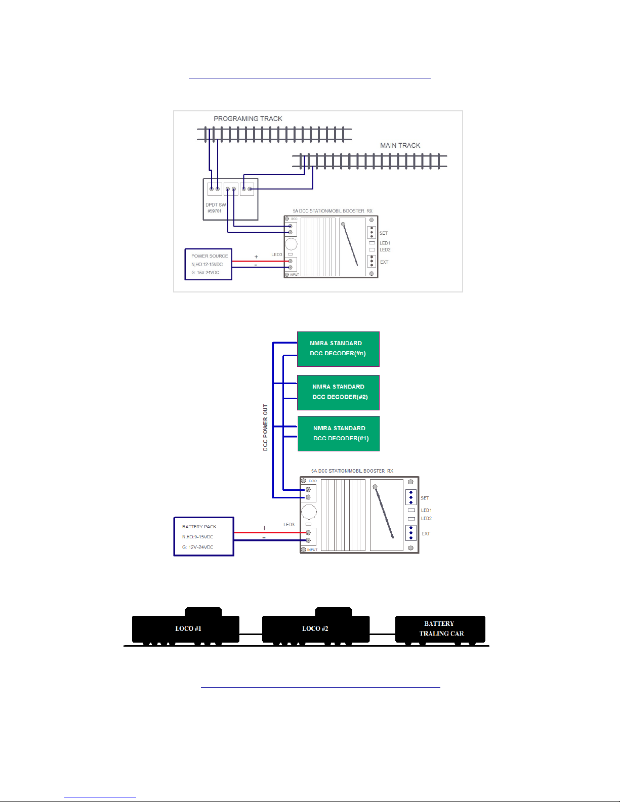
DIAGRAM FOR RECEIVER INSTALLATION SET UP
5A DCC RX TRACK POWER MODE
(FIG-1)
DIAGRAM FOR BATTERY INSTALLATION SET UP
2.4GHz DCC R/C System <TENTATIVE> 4
(FIG-2)
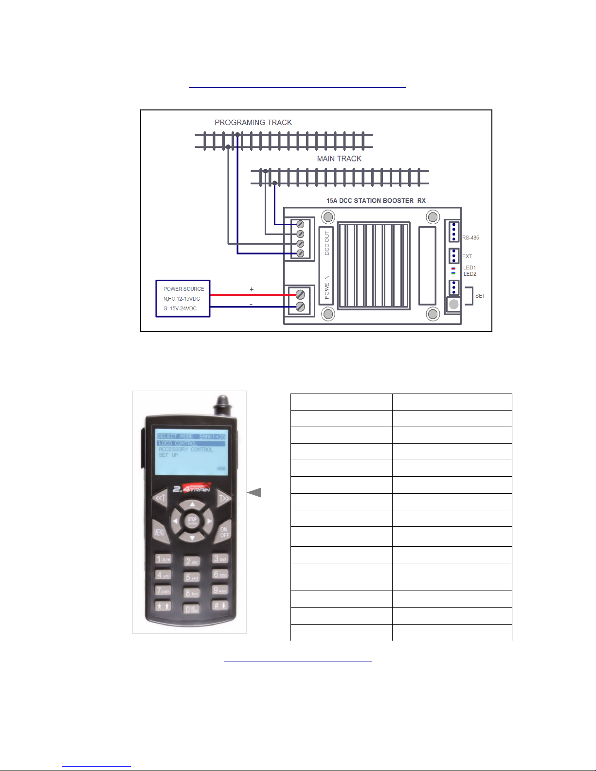
DIAGRAM FOR TRACK INSTALLATION SET UP
15A DCC STATION BOOSTER RX TRACK POWER MODE
Note:
Power source for N ,HO, S: 12 – 15V DC
Power source for O,G :15 – 24V DC
(FIG-3)
Key-Pad letter Functions
<<T CAB # decrease
T>> CAB # increase
STOP Stop/Enter
▲ Increase Speed
▼ Decrease speed
◄ Direction change
► Direction change
Asterisk Quick Program
# Qiuck menu
(0) all stop Function Control
MENU Select menu
1--9 Function control
ON/OFF Power ON/OFF
TRANSMITTER KEYPAD LABEL
Emergency all stop
2.4GHz DCC R/C System <TENTATIVE> 5
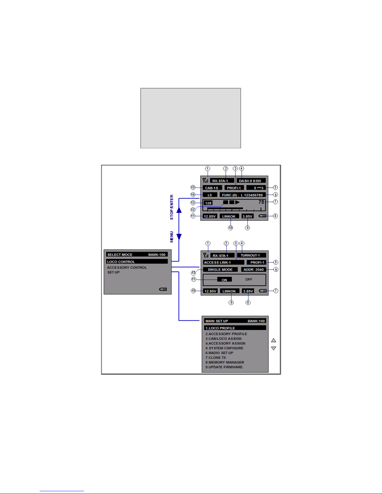
There are three concepts how to use the Revolution-DCC R/C System that need to be understand.
Refer to the LCD screen menu descriptions for details.
SELECT MODE BANK: 35
1) LOCO CONT/ROL
2) ACCESSORY CONTROL
3) SET UP
(FIG-4)
2.4GHz DCC R/C System <TENTATIVE> 6
 Loading...