

TENSITRON BTX-1 Series, BTX-50-1, BTX-100-1, BTX-500-1, BTX-250-1 Operating Instructions Manual
Page 1
Operating Instructions
BTX-1 Series Digital
Band Tension Meter
Page 2

BTX-1 Series Instrument Revised: 3.14.2018 www.tensitron.com pg. 2
TABLE OF CONTENTS
1. WARRANTY POLICY ..................................................................................................... 3
2. SPECIFICATIONS .......................................................................................................... 4
3. SAFETY AND MAINTENANCE ....................................................................................... 5
4. INSTRUMENT FEATURES ............................................................................................. 6
• Calibration and Accuracy ........................................................................................ 6
• Add-On Options ...................................................................................................... 6
o - A Analog Output option ................................................................................ 6
o - E RS-232 Serial Output option ...................................................................... 6
• Features of all Instruments .................................................................................... 6
5. BASIC OPERATION ....................................................................................................... 7
• Charging Instrument Batteries ............................................................................... 7
• Quick Start Instructions .......................................................................................... 8
• Engaging Instrument onto Band ............................................................................. 9
6. DISPLAY SCREENS ...................................................................................................... 10
• SETUP Screen ....................................................................................................... 10
o LCD Refresh Rate ............................................................................................. 10
o Data Averaging ................................................................................................ 10
o Custom Names ................................................................................................ 10
o Re-Cal Tension: See description at the end of this booklet. ............................ 11
o Audio ............................................................................................................... 11
o Backlight .......................................................................................................... 11
o Set-Point Menu ............................................................................................... 11
o Version ............................................................................................................ 12
• DATA LOGGING Screen ......................................................................................... 12
o View Data Stats ............................................................................................... 12
o View Data Log .................................................................................................. 12
o Clear Single Point Log ...................................................................................... 12
• TENSION UNITS Screen ......................................................................................... 12
• SELECT MATERIAL Screen ..................................................................................... 12
Page 3

BTX-1 Series Instrument Revised: 3.14.2018 www.tensitron.com pg. 3
7. ADVANCED OPERATION ............................................................................................ 12
• General Calibration Precautions .......................................................................... 12
• Check Accuracy .................................................................................................... 13
• Calibrate Instrument ............................................................................................ 13
Proprietary Notice
This document contains proprietary information which may not be
reproduced in whole or in part without the written permission of
Tensitron, 733 South Bowen Street, Longmont, CO 80501.
Tensitron reserves the right to make instrument changes and
improvements which may not be reflected in this document. Portions
of this document may have been updated to include the latest
hardware or firmware version, if applicable. We recommend that this
document be read in its entirety before any attempt is made to
operate the instrument.
Thank You . . .
For purchasing another fine product from Tensitron
If you have any questions or need assistance, please call us at
303-702-1980 or find us online at www.tensitron.com
1. WARRANTY POLICY
STANDARD EQUIPMENT WARRANTY
Tensitron warrants that all Tensitron-manufactured equipment will be free of any defect in materials or
workmanship for the period of (1) year. Warranty begins from the date of shipment from a Tensitron facility.
The warranty is extended to customers and applies to all Tensitron-manufactured equipment purchased,
installed, and used for the purpose for which such equipment was originally designed. The above warranties
cover only defects arising under normal use and do not include malfunctions or failures resulting from misuse,
abuse, neglect, alteration, problems with electrical power, usage not in accordance with product instructions,
acts of nature, or improper installation or repairs made by anyone other than Tensitron or a Tensitronauthorized, third-party service provider. Shipping costs to and from Tensitron are not included in the warranty
coverage.
Page 4
BTX-1 Series Instrument Revised: 3.14.2018 www.tensitron.com pg. 4
2. SPECIFICATIONS
Full Scale Accuracy
For the accuracy of each BTX-1 model, see Section 4.
Power Requirements
For Instrument Input: 9 VDC…2.2A
For AC Adapter: 100-240V~50-60Hz 0.48A
Power Supply operates with input voltages from 100 –240V and includes several interchangeable
adapters allowing use with European, U.S., Australian, English and other plug configurations.
Battery
Battery: Rechargeable NiMH, custom proprietary design
Battery lasts approximately 12 hours between charges, depending on backlighting intensity.
Operating Temperature
32º F to 120 º F.
If these values are exceeded, battery charge/discharge rates will decline. However, this could be
offset by using the power supply. Charging in direct sunlight or near a heat source will not
produce a full charge and may permanently damage battery pack.
Storage Temperature
20º F to 158º F. (Instrument and Charger)
Ambient Humidity
10% to 90% non-condensing
Weight, Dimensions
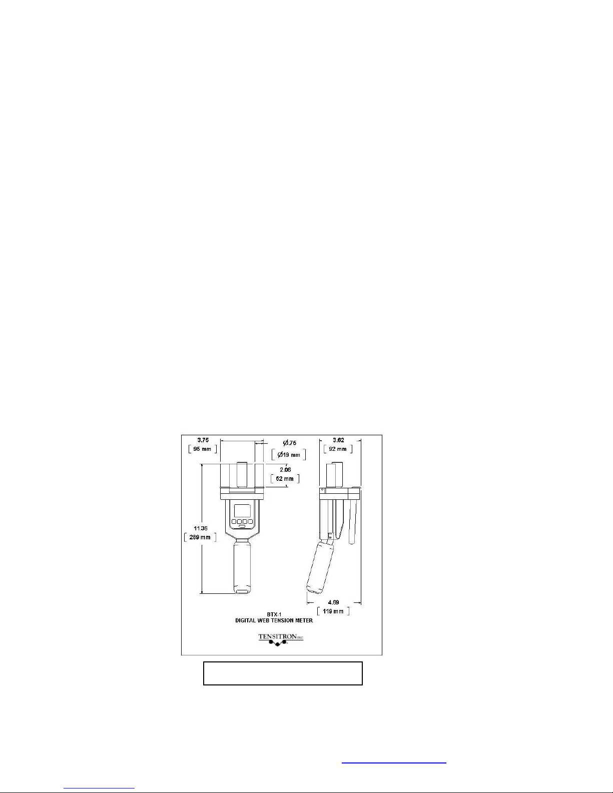
BTX-1: Weight 3.1 lb. Dimensions 3.8” x 11.4” x 4.7” (See Figure 1)
Environment
Indoor or outdoor use, dust-free environment.
Figure 1: BTX-1 Dimensions
Page 5

BTX-1 Series Instrument Revised: 3.14.2018 www.tensitron.com pg. 5
3. SAFETY AND MAINTENANCE
WARNING: When using cordless, electronic instruments, always follow basic
safety precautions to reduce the risk of fire, electric shock and personal injury
USE ONLY A TENSITRON POWER SUPPLY TO AVOID DAMAGE
TO INSTRUMENT.
READ AND SAVE ALL INSTRUCTIONS. Before use, ensure all users
read and understand this manual, as well as labels packaged with or
attached to the instrument.
• Know your instrument. Read this manual carefully to learn your tension
meter’s applications and limitations, as well as potential hazards
associated with this type of instrument.
• Avoid dangerous environments. Do not use your instrument in explosive
atmospheres (gaseous fumes, dust or flammable materials). Do not
submerge your instrument in liquids.
• Use the right tool or instrument. Do not use this instrument to do a job for
which it is not recommended.
• Check for damaged parts. Inspect instrument before use. Check for any
binding of moving parts, improper mountings, broken parts and any other
condition that may affect operation. Do not use a damaged instrument.
Tag damaged instrument “DO NOT USE” until repaired. For repair, send
instruments directly to Tensitron.
• Guard against electric shock.
• Maintain instrument carefully. Keep handles dry, clean and free from oil
and grease. Do not lubricate. All roller bearings are sealed.
• Do not use instrument if it has received a sharp blow, been dropped or
damaged in any way. Do not disassemble. Incorrect reassembly may
result in damage to the instrument and risk of electric shock and fire.
Return damaged instruments to Tensitron for repair.
• WARNING: Only use battery pack assemblies provided by Tensitron with
your meter. Other types of batteries might explode, causing personal
injury and damage. Unplug charger when not in use.
• Tensitron recommends calibration by the manufacturer at one-year
intervals, or sooner if the meter is worn, damaged, or reading incorrectly.
However, it is the user’s responsibility to establish a suitable calibration
interval, considering the user’s accuracy requirements, requirements set
by contract or regulation, and environmental factors such as frequency
and conditions of the meter’s use.
Page 6

BTX-1 Series Instrument Revised: 3.14.2018 www.tensitron.com pg. 6
4. INSTRUMENT FEATURES
• Calibration and Accuracy
BTX-1 instruments are calibrated to customer-supplied materials to ensure the
greatest possible accuracy for each application. When ordering, please provide
Tensitron with a sample (approximately 10-foot-long) of each material you’d like
included in the menu.
Accuracy is material-specific. Typical accuracy for BTX-1 instruments is
summarized in the table below, but actual accuracy may differ, depending on
the properties of the material used in the calibration:
Typical BTX-1 Accuracy
Model
Range (lb)
Resolution
(lb)
Full-Scale
Accuracy
BTX-50-1
5-50
0.5
2%
BTX-100-1
5-100
0.5
2%
BTX-250-1
5-250
0.5
2%
BTX-500-1
25-500
1.0
2%
• Add-On Options
NOTE: Instruments can be configured with either analog output or serial
output, but NOT both.
o - A Analog Output option
Data output at 40 Hz.
0-5 VDC or 4-20 mA with Software-definable ending sequences.
Provided with 10’ band to interface with your receiving device.
o - E RS-232 Serial Output option
Select data sampling rate from 1, 2 or 5 Hz.
Provided with 10’ band to interface with your receiving device.
o - R Custom Roller option
BTX-1 meters come standard with 2”-long Delrin rollers. Rollers are
also available in 3” length, or in stainless steel or aluminum.
• Features of all Instruments
• Color graphic display:
o Large and easy to read, with adjustable backlighting.
o Shows Tension, Battery Charge Level, and Band Material and
Size Selected.
o Includes user-definable tension set points.
• Data Statistics: Monitor your process by viewing count, average,
minimum/maximum, and standard deviation values of your logged data.
• Selectable Tension Units: Choose to display tension in Lb, Kg or daN.
Page 7

BTX-1 Series Instrument Revised: 3.14.2018 www.tensitron.com pg. 7
• Up to ten calibrations can be programmed into the instrument. (Password-
protected to provide due diligence against unauthorized changes.)
• Adjustable LCD refresh rates allow for stable digital readings.
• Automatic shutoff after several minutes of non-use.
• All models are typically available from stock.
• All models are factory calibrated and ready for use.
• All calibration values are traceable to National Standards.
• Calibration certificate is included.
• Continuous operation while connected to power supply.
• Durable, lightweight carrying case with protective foam inserts included.
(See Figure 2)
5. BASIC OPERATION
• Charging Instrument Batteries
1. Use only a Tensitron power supply to avoid damage to instrument.
2. Connect power supply to the instrument. Plug the power supply into a
power source with input voltages between 100 – 240 VAC.
3. A full charge of the battery assembly requires several hours of
charging.
4. Battery pack assembly cannot be overcharged.
5. Instrument will remain on while connected to its power supply.
6. Battery charge level is indicated in upper, right-hand corner of display.
Figure 2: Carrying case with instrument, calibration
certificate, charger, adapters, and operating instructions.
Page 8

BTX-1 Series Instrument Revised: 3.14.2018 www.tensitron.com pg. 8
• Quick Start Instructions
1. Power unit on by pressing ON button. Main display will indicate:
Tension, Material, Min and Max readings and other information. (See
Figure 3.)
2. Select a screen:
a. Move between screens by using the up (↑) and down (↓)
buttons.
b. Make or enter a selection by pressing the Enter/Zero button.
c. Exit a setting by pressing the Escape (ESC) button.
3. Log Data:
a. Press the STORE button to store tension readings along
with the Minimum and Maximum of these values.
b. Clear the data displayed on the Main Screen by pressing
and holding the STORE button, or power the instrument off.
c. For additional information on logging and viewing data, refer
to Sec 6 Display Screens - Data Logging.
4. Read Tension: Variations in band (material, thickness and width)
affect tension readings. It is essential to select the correct material
and size before use, or tension values may be incorrect.
Instrument Operation Panel
Main Display
Operation Buttons:
Off / Escape
On / Enter / Zero
Arrow Up
Arrow Down
Store
Main Display
Battery Charge Level
Selectable Units in Kg, daN, Lbs
Set Point Display
Select Band Size – Instrument
automatically adjusts calibration
Store and Display Max and Min Tension
Readings.
Figure 3: Instrument Operation Panel and Display
Page 9

BTX-1 Series Instrument Revised: 3.14.2018 www.tensitron.com pg. 9
5. Select Tension Units:
a. Using the up or down arrows, scroll to TENSION UNITS,
then press ENTER.
b. Next, select from: Kilograms, DecaNewtons, or Pounds, and
then press ENTER.
6. Select Material:
a. Using the up or down arrows, scroll to SELECT MATERIAL,
then press ENTER.
b. Next scroll through the band descriptions until the correct
band size/material is highlighted, then press ENTER. Your
main display will indicate the band size selected. (See
Figure 4)
c. If your specific material is not listed, add it to the menu by
following the calibration instructions included at the end of
these instructions. Or, send a 10’ sample of your
material/band and the instrument to Tensitron and ask to
have it added to the menu.
Zero
Instrument: Hold the instrument in the attitude your reading will be taken before you
engage it to the tensioned band. Then, press ZERO.
• Engaging Instrument onto Band
▪ To engage the instrument onto the tensioned band, start with the
meter’s lever released, so the center sensor roller is lowered.
▪ Position the meter so the band passes under the two outer guide
rollers and over the center sensor roller. Do not exceed the
maximum tension range of the instrument or damage will occur.
(See Figure 5)
▪ Squeeze the lever gently shut until the rollers close onto the material.
Note: If it takes a lot of force to close the lever, STOP! Closing the
lever with excessive force will damage the instrument.
▪ Note the tension reading on the display. (See Figure 5)
Select band size –
Instrument automatically
adjusts calibration
Figure 4:
Select Material Screen
Page 10

BTX-1 Series Instrument Revised: 3.14.2018 www.tensitron.com pg. 10
6. DISPLAY SCREENS
• SETUP Screen
o LCD Refresh Rate
To either speed up or slow down the instrument’s LCD refresh rates:
▪ Scroll to SETUP and press ENTER.
▪ Scroll to LCD REFRESH RATE and press ENTER.
▪ Select your preference: 1, 2 or 5 Hz and press ENTER.
Note: This feature is unrelated to Data Averaging
o Data Averaging
Use the Data Averaging feature to adjust the stability of your displayed
tension readings in processes where the material to be checked is
constantly moving. This feature averages all of the readings taken over
a user-selected duration, then posts that average to the display, in an
ongoing, rolling average. The duration can be set at 1, 2, 5 and 10
seconds.
Examples: The meter takes ~300 readings per second, so if a 1-second
duration is selected, the meter will average all 300 readings before
posting the average of those readings to the display. Likewise, if a 10second duration is selected, the meter will average all 3000 readings
before posting the average of those 3000 readings to the display.
o Custom Names
Custom calibrations, listed as Custom 0 – 9, can be renamed so your
material appears as a selection on the Main Display. To rename a
Custom Calibration:
▪ Scroll to SETUP and press ENTER.
▪ Scroll to CUSTOM NAMES and press ENTER.
Note the routing of the band (under
the outer guide rollers and over the
center sensor roller) and the
tension reading on the display.
Figure 5: Instrument engaged onto
band.
Page 11

BTX-1 Series Instrument Revised: 3.14.2018 www.tensitron.com pg. 11
▪ Scroll to the description to rename and press ENTER.
▪ Input your custom name by using the up and down arrows to
select each number, letter, or character, followed each time
by ENTER.
▪ Continue pressing ENTER until all spaces in the description
have values, including blank spaces.
▪ Once your new name has been entered you will automatically
be returned to the SETUP screen.
o Re-Cal Tension: See description at the end of this booklet.
ONLY PERFORM THIS IF YOU ARE A QUALIFIED CALIBRATION HOUSE USING NIST-CERTIFIED
CALIBRATION WEIGHTS. NOT USED FOR CHECKING ACCURACY. TO CHECK ACCURACY, REFER TO
SEC. 7: CHECK ACCURACY.
o Audio
To turn the Beep ON or OFF:
▪ Scroll to SETUP and press ENTER.
▪ Scroll to AUDIO and press ENTER.
▪ Select ON or OFF and press ENTER.
o Backlight
To adjust the visual intensity of the LCD screen.
▪ Scroll to SETUP and press ENTER.
▪ Scroll to BACKLIGHT and press ENTER
▪ Select Low, Medium or Full intensity and press ENTER.
o Set-Point Menu
This feature displays tension as a colored bar on the main display. The
colored bar advances as tension increases, and retracts as tension
decreases. You can define a safe operating tension range. For tension
measurements within this range, the bar is green. Below the range, the
bar is amber. Above the range, the bar is red.
To adjust the Set Point Menu:
▪ Scroll to SETUP and press ENTER.
▪ Scroll to SETPOINT MENU and press ENTER.
▪ Follow and enter the prompts to turn this feature on or off, or
to edit your high and low values. (See Figure 6)
Set Point Setup Screen
See High and Low threshold values
Settings:
On / Off
Edit High Point Threshold
Edit High Point Threshold
Figure 6: Setpoint Setup
Page 12

BTX-1 Series Instrument Revised: 3.14.2018 www.tensitron.com pg. 12
o Version
Press this button to determine what Model the instrument is set at in the
firmware as well as to see what level of firmware is downloaded to the
Instrument.
• DATA LOGGING Screen
Each time the instrument’s STORE button is pressed, a log of that band tension
will be stored into memory for later review.
o View Data Stats
This feature allows the operator to view the basis statistics of the
logged data (Count, Average, Minimum/Maximum, and Standard
Deviation).
o View Data Log
When data is logged to the instrument memory, that data and the
statistics of that data log (Count, Average, Minimum/Maximum, and
Standard Deviation) can be seen under the Data Logging / View Data
Stats screen. To view this logged data:
▪ Scroll to DATA LOGGING and press ENTER.
▪ Scroll to VIEW DATA LOG and press ENTER.
o Clear Single Point Log
To clear stored data, scroll to CLEAR SINGLE PT LOG, press ENTER,
and follow the prompts.
• TENSION UNITS Screen
To change the unit of measure in which tension readings are logged:
▪ Scroll to Tension Units and press ENTER.
▪ Use the Up and Down arrows to select Kilograms,
DecaNewtons or Pounds and press ENTER.
• SELECT MATERIAL Screen
Press ENTER while this display is shown to show the available options for the
material types. Use the up or down arrow to scroll to the option you want and
press ENTER to select it.
7. ADVANCED OPERATION
• General Calibration Precautions
1. To verify the accuracy of your instrument, check the tension on a sample
length of band by suspending known weights from the opposite end.
2. When performing this test, use a micrometer to measure your band
thickness and ensure it is dimensionally within tolerance.
3. Only use free-hanging weights which are traceable to National Standards
on correctly-sized bands. (See Figure 7.)
4. Never use any tensioning device that attempts to convert rotational torque
values into tension loads, as these types of systems are highly inaccurate.
Page 13

BTX-1 Series Instrument Revised: 3.14.2018 www.tensitron.com pg. 13
Also, any load cell system must be routinely checked for accuracy using
traceable weights as these types of systems are also highly inaccurate
and generally do not meet the minimum repeatable accuracy standards
required by ISO-17025.
• Check Accuracy
1. Confirm that the size band you’re working with is the same as the one
selected in your BTX’s display.
2. Before engaging the BTX-1 instrument onto the band, zero the instrument
by holding it in the same attitude you’ll be taking the readings and press
the “Enter” or “Zero” button. This will eliminate any small tare effects.
3. Take readings along the band. FOR BEST RESULTS ALWAYS TAKE
SEVERAL READINGS OF THE BAND TENSION BY DISENGAGING
AND THEN RE-ENGAGING THE INSTRUMENT FROM THE BAND
ITSELF.
4. Verify the tension value. For example, if your suspended weight is 40.0 lb.
your instrument should also indicate 40.0 lb. +/- the full-scale accuracy
percentage of the specific instrument model listed in Section 4, once
properly engaged to the band. This procedure confirms the instrument’s
accuracy and it is now ready for use.
Note: Accuracy Specification: NOTE, ACCURACY IS MODEL
DEPENDENT. For an instrument with a full-scale range of 250 lb., this
translates into +/- 5 lb., and for an instrument with a full-scale range of
500 lb., accuracy is +/- 10.0 lb. (with a 2% Accuracy Specification).
If you have additional questions, please contact Tensitron for help.
• Calibrate Instrument
*IMPORTANT: THIS FEATURE SHOULD ONLY BE USED BY A CALIBRATION FACILITY USING CERTIFIED AND
TRACEABLE DEAD WEIGHTS. DO NOT USE THIS FEATURE FOR A SIMPLE ACCURACY CHECK.
If you want to verify or check the accuracy of a calibration go to: “Check
Accuracy” in Section 7: Advanced Operation.
When calibrating these instruments tension values must be entered in
Lbs. Note: If your dead weight standards are in Kilograms, convert their
values into Lbs: 1 KG = 2.2046 Lbs
Page 14

BTX-1 Series Instrument Revised: 3.14.2018 www.tensitron.com pg. 14
Follow these instructions to update the calibration for an existing band on
the menu or to add a calibration for a new band. If you would like to add a
new band, first create a name for it by following the instructions under
“Custom Names” in Section 6, above.
1. Scroll to SETUP and press ENTER. Next, scroll to RE-CAL TENSION and press
ENTER. The screen will now display: SETUP, RE-CALIBRATE TENSION,
ENTER PASSWORD, CAL DATA WILL BE LOST!
2. Enter Password. Contact Tensitron at service@tensitron.com for the password.
3. The display now indicates: SETUP RE-CALIBRATE TENSION with a list of the
calibration names and custom names programmed into the instrument. Scroll to
the description you wish to recalibrate, highlight it and then press ENTER.
4. The next screen will indicate: CALIBRATE TENSION, NUMBER OF POINTS.
Using the up and down arrows select the number of calibration points to which you
will be tensioning the band. The minimum is 5 points. Zero is a calibration point
already set, so you will need to define a minimum of 4 increasing tension values
such as: 50, 100, 150 and 200. If desired you can define more than 5 weight
points, with a maximum of 10 points total. If 10 calibration points were selected the
entries could look something like this: 10, 20, 30, 40, 50, 60, 70, 80, 90.
Figure 7: Free hanging weight
simulating band tension.
Page 15

BTX-1 Series Instrument Revised: 3.14.2018 www.tensitron.com pg. 15
5. ENTER WEIGHT. After selecting the number of calibration points, you need to
define these weight values. Using the up or down arrows select your first tension,
or weight calibration point and press ENTER. Do not use 0 (zero) as this value is
already programmed into the instrument. Next, use the up or down arrows to select
your weight 2 value, making sure the value entered is greater than the entry in
weight 1. Next, select increasing weight values for the additional weight points,
without exceeding the maximum tension range of the instrument.
6. CALIBRATE TENSION. Next you will calibrate the instrument using the weight
values you previously selected. To properly simulate these tensions, suspend a
single length of your band from above and suspend known weights onto the band
in the values you’ve previously selected, when prompted. (See Figure 7.)
a. CALIBRATE TENSION, NUMBER OF POINTS __, ZERO UNIT.
Without any band engaged to the instrument, hold it in the
attitude you will be taking the reading in and press ENTER to
calibrate zero weight. Next the display will prompt you to
suspend the weight value you previously selected in step 5. If,
for example you selected 50 lb. for your first weight value the
instrument will indicate: PLACE WEIGHT 50.
b. Suspend the exact weight value from your band that you’ve
previously selected (In this example it would be 50 lb.)
c. Next, engage the instrument to your tensioned band, then press
ENTER once the reading has stabilized.
d. Repeat steps b. and c. for the remaining weight points by
suspending additional weights onto your band in the values
previously selected and entering these readings.
e. Once the last weight value is entered, the instrument will return
to the SETUP menu. Press the ESCAPE button to return to the
main display.
f. The main display will now indicate the band/material description
you just finished calibrating. If the material name on the display
is not the material you just recalibrated, you have reprogrammed the incorrect description. If this happens, you will
need to recalibrate both the material indicated on the display
along with the material you thought you were calibrating.
g. After completing a calibration always recheck the values. Refer
to “Check Accuracy” in Section 7.
Page 16

733 S. Bowen Street
Longmont, CO 80501
USA
Phone: (303) 702-1980
Fax: (303) 702-1982
E-mail: sales@tensitron.com
Band Site: www.tensitron.com
 Loading...