

Page 1
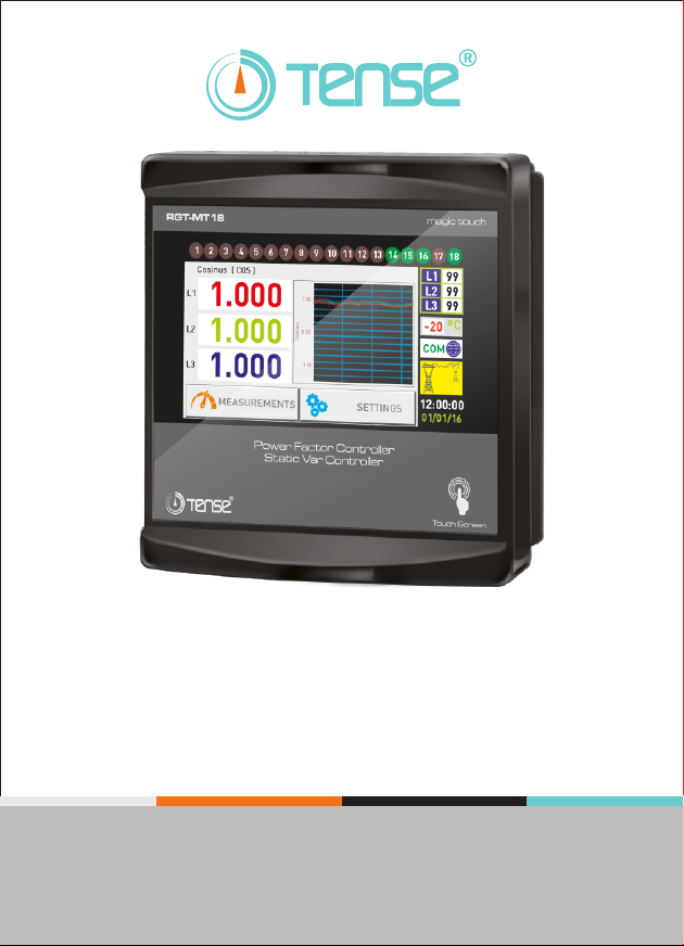
RGT-MT18
USER GUIDE
www.tense.com.tr
Page 2

Contents
About RGT-MT18
Features
About RGT-MT
Warnings
Considerations in Compensation
What to Look Out for in the Selection and Connection of Current Transformer?
How to Connect the NTC to the Panel Temperature?
Maintenance of the Device
Screen Intro
1 Measurements Page 1
1.1 Voltage Page
1.2 Voltage & Current Page
1.3 Voltage & Frequency Page
1.4 Instant Powers Page
1.5 Ratios Page
1.6 Power Factor Page
1.7 Total Energy Pages
1.8 THD-V THD-I Page
2 Measurements Page 2
2.1 Power Analysis Page
2.2 Step Values Page
2.3 Cosine Page
2.4 Harmonic Voltage Page
2.5 Harmonic Current Page
2.6 Demand Page
2.7 Min / Max / Average Page
3 Settings Screen
3.1 Current Transformer Settings
3.1.1 Current Transformer Test
3.1.2 Changing the Current Transformer Value
3.2 Voltage Harmonic Protection
1
1
2
2
3
3
4
4
4
5
5
5
6
6
6
6
6
7
7
7
8
8
8
8
9
9
9
10
10
10
10
Page 3

Contents
3.3 Current Harmonic Protection
3.4 Generator Compensation Setting
3.5 Voltage Protection
3.6 Inductive and Capacitive Alarm
3.7 Compensation Target Setting
3.8 Temperature Control
3.9 ModBus Settings
3.10 Step Settings Page
3.10.1 Step Times
3.10.2 Entering the Manual Step Value
3.10.3 Automatic Step Measurement
3.10.4 PFC Setting
3.10.5 Step Test
3.11 Device Settings
3.11.1 Device Installation
3.11.2 Language Selection
3.11.3 Password Settings
3.11.4 Delete Registration
3.11.5 Factory Settings
How to Select a Home Page?
How to Install the Device?
How to Change the Current Transformer Value?
How is the Current Transformer Test Done?
How to Measure the Step?
How to Enter the Manual Step Value?
How to Perform a Step Test?
How to Return to Factory Settings?
How to Return to the Default Menu Settings?
Three Phase (3P4W) Connection Scheme
Single Phase Connection Scheme in Three Phase System
Remote Communication with RS485 (GSM-MOD)
Remote Communication with RS485 (ETH-MOD)
11
11
11
12
12
12
13
13
13
14
14
15
15
15
16
16
16
17
17
18
19
19
20
20
21
21
22
22
23
24
25
25
Page 4

Contents
Calculation Chart of Capacitor According to Connection
Step Creation According to Power Analysis Examples?
Dimensions
Factory Default Values
Technical Specifications
Contact Information
User Notes
26
27
28
29
30
30
31
Page 5

About RGT-MT
It is designed to reduce reactive (inductive and capacitive) power that comes from the
network and loads do not use. If the inductive reactive power is attracted from the network,
it interferes by attracting capacitor at the appropriate step. If capacitive reactive power is
attracted from the network, t interferes by attracting shunt reactor at the appropriate step.
Thus it endeavors to reduce the inductive/active and capacitive/active rates of the system.
It is designed to make more sensible compensation at the unbalanced inductive and
capacitive systems with RGT-MT18 TCR(SVC) step.
Features
5 "Easy to install and use with touch (resistive) display
TCR (SVC) Connectable
Generator Input and Generator Compensation
Remote Communication with RS485 (Computer Communication)
Temperature Measurement and Control
Compensation for Inductive and Capacitive Systems
Manual Step Value Enterable
Single, Two, and Three Phase Capacitor and Shunt Reactor can be Connected
Turkish and English Language Option
Voltage, Harmonic Current/Voltage, Inductive and Capacitive Alarm Output
Temperature Alarm Output
Intervention, Discharge and Settling Times can be Adjustable
Current Harmonics can be Observed Up To 61st Harmonics
Voltage Harmonics can be Observed Up To 61st Harmonics
Cosine Values of Each Phase Can Be Observed
Power Factor Values of Each Phase can be Observed as Graphically
Capacitive / Active and Inductive / Active Ratios can be Observed as Grafically.
Total Energies (Import/Export) can be Observed.
THD-V and THD-I values of Each Phase can be Observed.
Creating Power Analysis (20 samples 9999 min.)
Demand Registration (Active & Reactive & Apparent Power and Current Demand)
Min, Max and Average Values of Current and Voltage of Each Phase can be Observed.
Real Date and Time
Encrypted Protection
Same Aging in Steps
1
Page 6

Warnings
Use the device according to our instructions.
Avoid direct sun light in order not to harm the LCD screen.
Leave at least 10 cm of space behind the device after mounting.
Fix the device with apparatus which comes within the device by avoiding any kind of
shake on the front cover of the board.
Balance the inner and outer heat in the metal boards. Otherwise because of the
temperature difference that originates from the dampish surrounding, water droplets
occurs on the ceiling of the board and this situation is dangerous for the open connected
buses.
Mark the switch and circuit breaker as the connection tripping element for the device.
Keep the switch and circuit breaker close to the device and easily accessible by the
operator.
There must be no electricity in the connection cables when assembling.
Screened and twisted cord cables should be used on the input and output lines without
connection to the Mains (network). These cables should not pass near high-Voltage lines
and devices.
Do not touch the touchscreen with a hard, sharp object.
Matters to Be Considered In Compensation
Compensation starts with the regulations of the load distribution of the Electrical
wiring in a balanced way that belongs to the system.
Connect three phase capacitor with high value to the first three step (C1, C2, C3) for the
current transformer test.
Do not define step number and capacitor values randomly where has rapid load changing
and where huge amount of load is distributed randomly.
You can get benefit from the examples which are in the Power Analysis, in order to
compensate more effectively to the unbalanced loads in the system.
It is advisable to add new steps at the same value for the lifespan of the commonly used
step's conductor and capacitor.
While preparing compensation board be careful about that you should easily add new
steps for probable changings (load adding or excluding) that can occur subsequently.
While making current transformer test and measurement of the step, be careful about
avoiding rapid load changing on the system as much as possible.
Choose the automatic fuse current values used in steps according to the power of the
capacitor and reactor and point as connection removing member.
Use different automatic fuse for each feeding inductor of the step conductors.
Use compensation conductor sand discharge inductors at the steps.
Unique phase connection at the three phase systems is only appropriate for balanced
load attraction. Otherwise desired rates cannot be obtained.
2
Page 7
Point to Pay Attention About The Choice And Connection of the Current
Transformers
Be careful about the value of the current transformer to be more than the maximum
current which could be/is attracted from the system.
It is recommended that class of the current transformers (it can be also mentioned
class, klas, kl, cl ) should be 0,5 which will be used at the compensations.
Only X5A current transformers can be connected to the RGT-MT18.
Be careful about the absence of any load before the current transformers. Otherwise
there can be differences between reactive and counter.
Current transformer outputs and phase inputs must be in the same order. Connect the
k-l terminals of the current transformer connected to the L1 phase to the k1-l1
terminals, the k-l terminals of the current transformer connected to the L2 phase to the
k2-l2 terminals and the k-l terminals of the current transformer connected to the L3
phase to the k3-l3 terminals.
While connecting output of the current transformer terminals in order to avoid
confusion, use different coloured cable for each phase or number the cables.
Pass the cables which is connected to the output of the current transformer far from the
high voltage line.
It is advised that the cables to be used which are connected to current transformer
should be minimum 1.5 mm2. It is also recommended that the cables should be
thickened as the distance increase.
In order to avoid shake at the current transformers, fix to the bus, cables or rail.
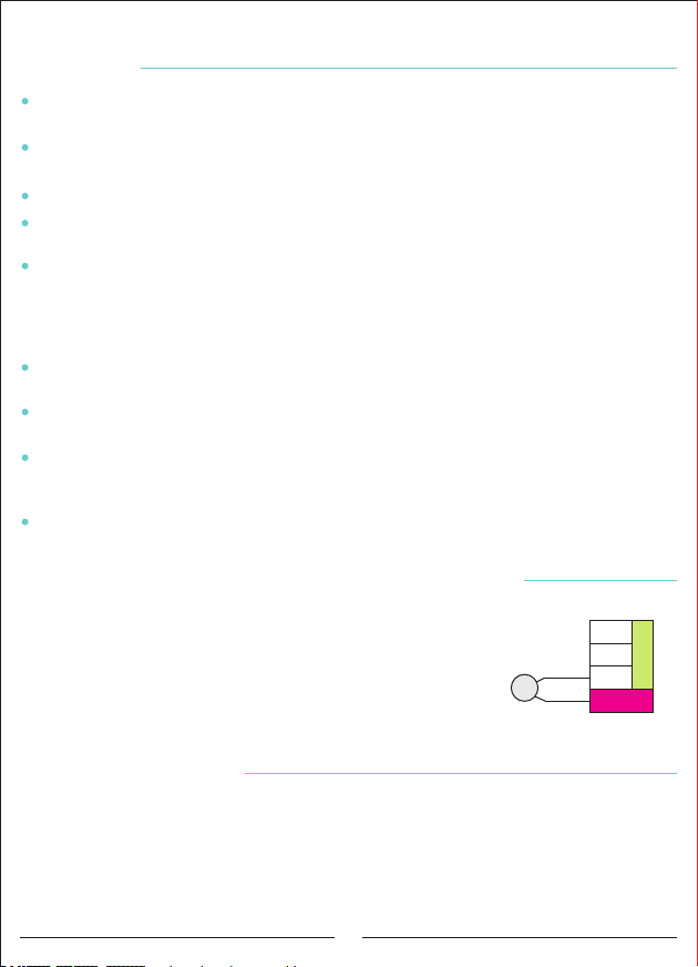
How to Connect the NTC to Inside of the Panel Temperature?
In order to measure the surrounding temperature of the panel,
NTC terminal will be attached which comes within the device.
NTC's one terminal will be attached to the RS485 connection's
GND, the other terminal will be connected to the NTC. When the
connection accomplished, panel heat value is seen on the screen.
When the connection disconnected or reach to the -40, ''NC'' sign
is seen on the screen.
NTC
(10K)
A
B
SGND
NTC
SVC CON
Maintenance of the Device
Turn off the energy of device and disconnect it from the connections. Clean the body of
the device with a slightly damp or dry cloth. Do not use conductive or other chemicals that
may damage the device as a cleaning materials. After the device is cleaned, make
connections and make sure that the device is working by energizing the device.
3
Page 8
Screen Introduction
5
6
3 4
1 2
Voltage L-N
L1 L12
220.0
L2
220.0
L3
220.0
MEASUREMENTS
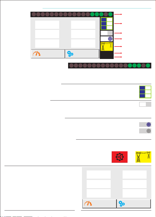
1- Step LEDs:
It shows the which step?
7 8
V
V
V
111213 14
10
9
Voltage L-L
380.0
L23
380.0
L31
380.0
3 4
1 2
SETTINGS
5
15 16 17 18
L1
L2
V
L3
-20
V
COM
V
12:00:00
01/01/16
6
7 8
99
99
99
ºC
9
111213 14
10
1
2
3
4
5
6
7
15 16 17 18
The display background becomes red when the step is switched on. When the step is
switched off, the display background color is gray. It has no touch feature.
2- TCR (SVC) Step Indicator:
It shows separately the driving ratios of the mono-phase shunt reactors
connected to the SVC. It has no touch feature.
3- Temperature Indicator:
Indoor temperature is shown in °C. When the NTC connection fails or when the
-20
temperature it goes below -40 ºC, "NC" is written in the value display. It has no touch
feature.
4- Remote Communication Indicator:
It displays for 1 second when remote communication with RGT-MT18.
The passive image is displayed when no remote communication is made.
It has no touch feature.
Active
Passive
COM
COM
5- System Feed (Voltage) Source Indicator:
Indicates that the system is fed from the network or generator.
When voltage (220V) is applied to the generator input, the system
Generator
Supply
Network
Supply
is supplied from the generator. If there is no voltage at the
generator input, it means that the system is being fed from the
network. It has no touch feature.
6- Dynamic Display:
Touch-screen is active on this area.
By pressing the buttons in the area,
the measured values can be seen and the
settings can be changed.
Voltage L-N
L1 L12
220.0
L2
RGT-MT
220.0
Sabit Bildirim Ekranı Tanıtımı
L3
220.0
MEASUREMENTS
4
V
V
V
Voltage L-L
380.0
L23
380.0
L31
380.0
SETTINGS
L1
99
L2
99
L3
99
ºC
V
V
V
Page 9
Measurements E
V
Voltage
P
+
Q
Instant Powers
kWh
kVArh
Total Energy
1. Measurements Page 1
MEASUREMENT PAGE-I
&
V A
Voltage&Current
-
+
Q
-
Q
P
Reactive Ratios
V &A
THD-V THD-I
Q
&
F
V
Voltage&Freq.
P F
Power Factor
2
Measurements-II
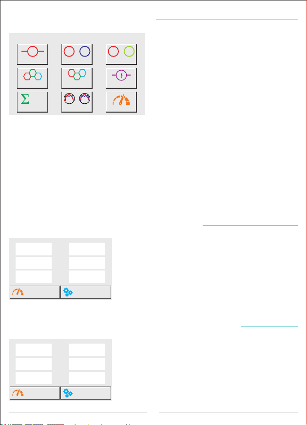
When the Measurements button is pressed,
the measurements page-1 comes to the
dynamic area. From this page you can switch
between Voltage, Voltage & Current, Voltage &
Frequency, Instantaneous Power, Ratios,
Power Factor, Total Energy, THD-V THD-I and
Measurements-2 page.
1.1 Voltage: Phase-Neutral and Phase-Phase voltage values are displayed.
1.2 Voltage&Current: Voltage and current values are displayed.
1.3 Voltage&Frequency: Voltage and Frequency values are displayed.
1.4 Instant Powers: Instant active and reactive power are displayed.
1.5 Reactive Ratios: Capacitive / Active and Inductive / Active ratios are shown.
1.6 Power Factor: The power factor values are shown in figures and graphs.
1.7 Total Energy: Total Active, Inductive and Capacitive energies are shown.
1.8 THD-V/THD-I: Total Harmonic Voltage and Current values are displayed.
2. Measurements-II: goes to Measurements Page 2.
Measurements E
Voltage L-N
L1 L12
220.0
L2
220.0
L3
220.0
V
V
V
MEASUREMENTS
Measurements E
Voltage L-N
L1 L1
220.0
L2
220.0
L3
220.0
V
V
V
MEASUREMENTS
Measurements Page 1 E
Voltage L-L
380.0
L23
380.0
L31
380.0
SETTINGS
In this page, the phase-neutral and phase-to-phase
V
voltage values are displayed for each phase.
V
On this page, the "Measurements 1" page is displayed
when the "Measurements" button is pressed, and the
V
"Settings" page is displayed when the "Settings" button
is pressed.
Measurements Page 1 E
Current
1.358
L2
1.453
L3
1.289
SETTINGS
In this page, the phase-neutral voltage values of each
A
phase and the current values of each phase are displayed.
A
On this page, the "Measurements 1" page is displayed
when the "Measurements" button is pressed, and the
A
"Settings" page is displayed when the "Settings" button
is pressed.
1.1 Voltage Page
1.2 Voltage & Current Page
5
Page 10
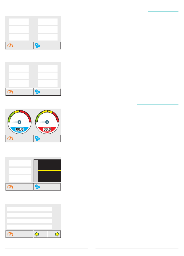
Measurements E
Voltage L-N
L1 L1
220.0
L2
220.0
L3
220.0
V
V
V
MEASUREMENTS
Measurements E
Active Power (kW)
L1 L1
0.000
L2
0.000
L3
0.000
MEASUREMENTS
Measurements E
15
20
10
5
25
30
0
Capacitive/Active R. (%)
00.0
MEASUREMENTS
Measurements E
Power Factor
L1
-0.999
L2
-0.999
L3
-0.999
MEASUREMENTS
Measurements E
Total Energies
234.999
234.999
234.999
234.999
MEASUREMENTS
Measurements Page 1 E
Frequency
50.00
L2
50.00
L3
50.00
In this page, the phase-neutral voltage values of each
Hz
phase and the frequency values of each phase are displayed.
Hz
On this page, the "Measurements 1" page is displayed
Hz
when the "Measurements" button is pressed, and the
"Settings" page is displayed when the "Settings" button
SETTINGS
is pressed.
Measurements Page 1 E
Reactive Power (kVAr)
0.000
L2
0.000
L3
0.000
In this page, the active power and reactive power values are
displayed.
On this page, the "Measurements 1" page is displayed
when the "Measurements" button is pressed, and the
"Settings" page is displayed when the "Settings" button
SETTINGS
is pressed.
Measurements Page 1 E
15
10
5
0
Inductive/Active R. (%)
00.0
In this page Capacitive / Active and Inductive / Active ratios
20
25
are displayed as “%” in figures and graphs.
30
On this page, the "Measurements 1" page is displayed
when the "Measurements" button is pressed, and the
"Settings" page is displayed when the "Settings" button
SETTINGS
is pressed.
Measurements Page 1 E
1.00
0.00
Power Factor
-1.00
SETTINGS
In this page, the Power Factor values are displayed in
figures and graphs.
On this page, the "Measurements 1" page is displayed
when the "Measurements" button is pressed, and the
"Settings" page is displayed when the "Settings" button
is pressed
Measurements Page 1 E
+P (Imp)
In this page, total energy values (import active, inductive,
kWh
+Q (End)
capacitive and export active) are displayed.
kVArh
-Q (Kap)
kVArh
On this page, the "Measurements 1" page is displayed
-P (Exp)
kWh
when the "Measurements" button is pressed. When you
press the "BACK" and "NEXT" buttons, you can see the
NEXTBACK
Energy for each phase, Energies of tariffs and Energy values
of Generators.
1.3 Voltage & Frequency Page
1.4 Instant Powers Page
1.5 Reactive Ratios Page
1.6 Power Factor Page
1.7 Total Energies Pages
6
Page 11
Measurements E
THD-V
L1 L1
0.000
L2
0.000
L3
0.000
MEASUREMENTS
Measurements Page 1 E
THD-I
0.000
L2
0.000
L3
0.000
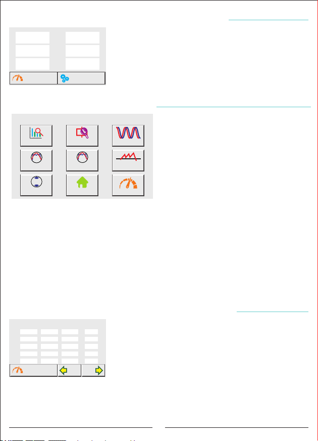
In this page, THD-V (Voltage total harmonic distortion) and
THD-I (Current total harmonic distortion) values of each
phase are displayed.
On this page, the "Measurements 1" page is displayed
when the "Measurements" button is pressed, and the
SETTINGS
"Settings" page is displayed when the "Settings" button
1.8 THD-V THD-I Page
is pressed.
Measurements E
2. Measurements Page 2
MEASUREMENT PAGE-II
When the Measurements-II button is pressed,
the measurements page-2 comes to the screen
Power Analysis
V
Volt.
Harmonics
Max
Min
Min/Max
Step Values
A
Cur. Harmonics
Main Page
Cosinus
Demand
1
Measurements-I
on the dynamic area.
From this page, it is possible to switch to
Power Analysis, Step Range, Cosine,
Harmonic Voltage, Harmonic Current, Demand,
Min / Max, Home and Measurements-1 page.
2.1 Power Analysis: The reactive (inductive and capacitive) records of the system are
displayed.
2.2 Step Value: Each phase of step values are shown.
2.3 Cosine: The cosine value is shown in figures and graphs.
2.4 Harmonic Voltage: Values up to the 61st harmonic of each phase are displayed.
2.5 Harmonic Current: Values up to the 61st harmonic of each phase are displayed.
2.6 Demand: Active / Reactive / Apparent power and Current demand values are displayed.
2.7 Min/Max: Current and Voltage Min / Max / Average values are displayed.
Main Page: Go to Main Page.
Measurements-I: Go to Measurements Page 1.
Measurements E
Power Analysis Samples
L1
0.00
0.00
0.000.00
0.000.00
0.00
0.00
0.00
0.00
MEASUREMENTS
L2
1.
2.
3.
4.
5.
Measurements Page 2 E
L3
0.00 0
0.00
0.00
0.00
0.00
In this page each reactive(capacitive is marked as (-) power
Time (min)
of the phase are recorded with their time.
0
0
If expenditure of power is fixed in a stated time, it is
0
recorded as sample. If latter sample is %15 higher than the
0
former, it is recorded as different. If it is %15 less than the
NEXTBACK
former, it is added to the sample. It ıncludes 20 samples in
2.1 Power Analysis Page
total. It can take samples up to 9999 minutes most.
In this page when you press the Measurements button ''Measurements 1'' page comes.
When you press ''BACK'' and ''NEXT'' button, you can pass among the samples.
7
Page 12
Measurements E
Step Values
L1 L2
1.
-0.33 -0.33
2.
-0,25
3.
0.00
4.
0.00
5.
0.00
MEASUREMENTS
0.00
-0,25
0.00
0.00
-0.33
0.00
0.00
-0,25
0.00
Measurements Page 2 E
L3
Connection Counter
L1-2-3
Cancel
L1
L2
L3
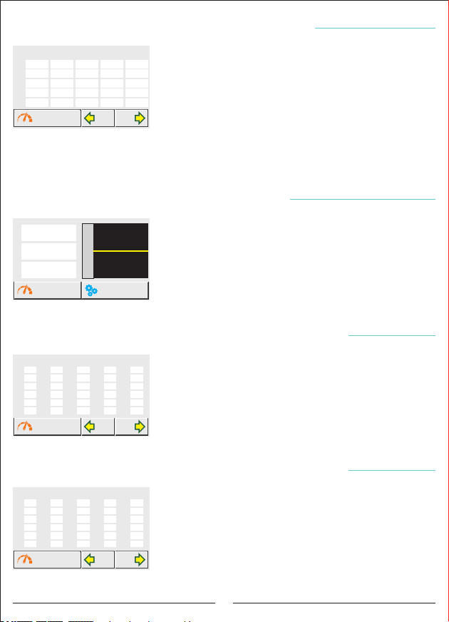
In this page, the values of capacitor (sign (-) or shunt
reactor value (each phase separately), connection type and
10
number of steps usage are displayed.
30
45
1
It is 18+1 step in total. The 19th step is TCR.
0
Three monophasi (one for each phase) shunt reactor are
NEXTBACK
connected to this step. Shunt reactors are connected to
2.2 Step Values Page
driver. Shunt reactors are triggered via the SVC CON
connection.
On this page, the "Measurements 1" page is displayed when the "Measurements" button
is pressed. When you press the "BACK" and "NEXT" buttons, you can pass from one step to
another step.
Measurements E
Cosinus ( COS )
L1
-0.999
L2
-0.999
L3
-0.999
MEASUREMENTS
Measurements Page 2 E
1.00
0.00
Cosine
-1.00
In this page, the cosine values of each phase are displayed
in figures and graphics.
On this page, the "Measurements 1" page is displayed
when the "Measurements" button is pressed, and the
"Settings" page is displayed when the "Settings" button is
SETTINGS
pressed.
2.3 Cosine Page
Measurements E
L1 - Voltage Harmonics
3.
15.
0.0 0.0 0.0 0.0 0.0
5.
17.
0.0 0.0 0.0 0.0 0.0
7.
19.
0.0 0.0 0.0 0.0 0.0
9.
21.
0.0 0.0 0.0 0.0 0.0
11.
23.
0.0 0.0 0.0 0.0 0.0
13.
25.
0.0 0.0 0.0 0.0 0.0
MEASUREMENTS
Measurements E
L1 - Current Harmonics
3.
15.
0.0 0.0 0.0 0.0 0.0
5.
17.
0.0 0.0 0.0 0.0 0.0
7.
19.
0.0 0.0 0.0 0.0 0.0
9.
21.
0.0 0.0 0.0 0.0 0.0
11.
23.
0.0 0.0 0.0 0.0 0.0
13.
25.
0.0 0.0 0.0 0.0 0.0
MEASUREMENTS
Measurements Page 2 E
27.
39.
29.
41.
31.
43.
33.
45.
35.
47.
37.
49.
Measurements Page 2 E
27.
39.
29.
41.
31.
43.
33.
45.
35.
47.
37.
49.
2.4 Harmonic Voltage Page
In this page, up to the 61st harmonic of each phase voltage
51.
53.
is displayed.
55.
57.
59.
On this page, the "Measurements 1" page is displayed
61.
when the "Measurements" button is pressed. When you
press the "BACK" and "NEXT" buttons, you can see
NEXTBACK
harmonics belong to the other phases.
2.5 Harmonic Current Page
In this page, it is displayed up to the 61st harmonic of each
51.
53.
phase current.
55.
57.
On this page, the "Measurements 1" page is displayed
59.
61.
when the "Measurements" button is pressed. When you
press the "BACK" and "NEXT" buttons, you can see
NEXTBACK
harmonics belong to the other phases.
8
Page 13
Measurements E
Current Demand (15min.)
Current (A) Date
L1
L2
L3
Total
0.000
0.000
0.000
0.000
MEASUREMENTS
00/00/0000
00/00/0000
00/00/0000
00/00/0000
Measurements E
Current Min-Max-Avg (A) (5min.)
Min Max
L1
L2
L3
MEASUREMENTS
0.000
0.000
0.000
0.000 0.000
0.000
Measurements Page 2 E
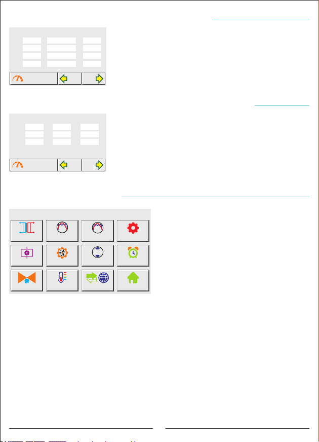
In this page, the total current, active power, reactive power
Time
and apparent power demand values are displayed with the
00:00
00:00
date and Times.
00:00
00:00
On this page, the "Measurements 1" page is displayed
when the "Measurements" button is pressed. When you
NEXTBACK
press the "BACK" and "NEXT" buttons, you can see other
demand values.
Measurements Page 2 E
In this page, the minimum (min), maximum (max) and
Avg
average (avg) values of current and voltage values are
displayed. (Values are taken with an average of 5 min.)
0.0000.000
0.000
On this page, the "Measurements 1" page is displayed
when the "Measurements" button is pressed. When you
NEXTBACK
press the "BACK" and "NEXT" buttons, it is toggle between
the others.
2.6 Demand Page
2.7 Min / Max / Average Page
Alarm
1
+Q
3. Settings Screen
SETTINGS PAGE
THDV SetV THDI Set
Generator
Temperature
A
V
Voltage Min/Max
ModBus
Device Settings
Alarm
Main Page
When the Settings button is pressed, the
Settings page appears on the screen on
dynamic area.
From this page, you can switch to Current
Transformer, Harmonic Voltage, Harmonic
Current, Device Settings, Step, Generator,
Voltage Min / Max, Alarm, Compensation,
Temperature, Modbus settings and Main Page.
Settings E
Current Trans.
Step Settings
-Q
PF Correction
3.1 Current Transformer : The current transformer test / current transformer value
change is made.
3.2 Harmonic Voltage: Harmonic Voltage settings are made.
3.3 Harmonic Current: Harmonic Current settings are made.
3.4 Device Settings: Go to Device settings menu.
3.5 Step: Go to the menu of Step settings.
3.6 Generator: Generator settings are made.
3.7 Voltage Min / Max: Voltage settings are made.
3.8 Alarm: Inductive and Capacitive Alarm settings are made.
3.9 Compensation: Inductive and Capacitive target settings are made.
3.10 Temperature: Temperature Alarm settings are made.
3.11 ModBus: Modbus (Communication) settings are made.
Main Page: Go to Main Page.
9
Page 14
Settings E
L1 - Harmonik Distorsiyon Gerilim
3.
0.0 0.0 0.0 0.0 0.0
5.
0.0 0.0 0.0 0.0 0.0
7.
0.0 0.0 0.0 0.0 0.0
9.
0.0 0.0 0.0 0.0 0.0
11.
0.0 0.0 0.0 0.0 0.0
Settings Page
13.
0.0 0.0 0.0 0.0 0.0
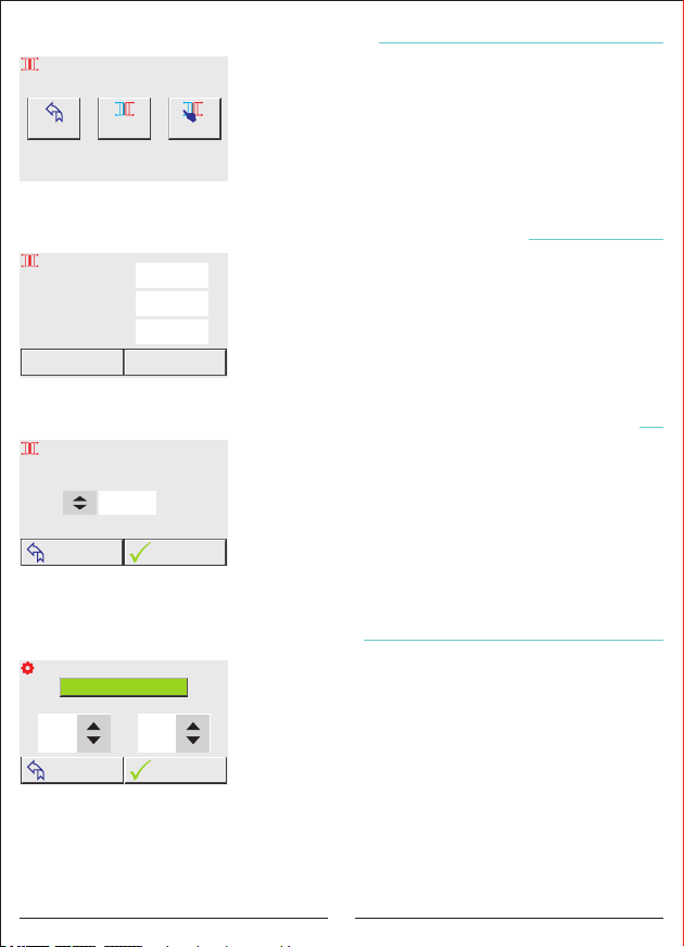
3.1 Current Transformer Settings
Current Transformer Settings
15.
27.
17.
29.
K k
19.
31.
L l
21.
33.
23.
25.
ÖLÇÜMLER
TEST
Start
35.
CT Test
37.
Back
39.
41.
43.
45.
47.
49.
Change Current
Transformer Ratio
In this page you can start the current transformer test and
51.
change the current transformer value.
53.
55.
X
5A
57.
On this page, when the "Start Current Transformer Test"
59.
button is pressed, the current transformer test is started.
61.
When the "Change Current Transformer Value" button is
ILERIGERI
pressed, the current transformer value changing page is
displayed on the screen.
When the "Back" button is pressed, the "Settings" page appears on the screen.
Current Transformer Test
CT Test was Started
Cancel
CT Test
Current Transformer ESettings E
Current
L1
380.0
L2
380.0
L3
380.0
Confirm
CT Connection
3.1.1 Current Transformer Test
The test starts automatically when the "Start current
A
transformer test" button is pressed. If there are any
problems in the connection, the device will give a warning
A
and will not accept the connection.
A
If the current transformer test is successful and the
connection is confirmed, the device starts to measure the
step automatically.
Current Transformer ESettings E
Enter the CT Ratio
3.1.2 Changing the Current Transformer Value
To set the current transformer value, press the up and
down arrow buttons on the screen after pressing the
0150
/5A
"Change current transformer value" button. The test starts
automatically when the "Confirm" button is pressed. If there
are any problems in the connection, the device will give a
warning and will not accept the connection.
OKTURN BACK
If the current transformer test is successful and the connection is confirmed, the device
starts to measure the step automatically.
Settings E
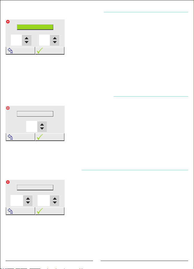
3.2 Voltage Harmonic Protection
THDV Protection Settings
THDV Control Mode Active
Delay (sn.)THDV Set (%)
2040
TURN BACK
In this page voltage harmonic control mode can be made
active or passive, harmonic of total voltage and delay of it can
be set. When the set is active the colour of the button's
writing becomes green, and when the set is passive it
becomes red. When the control mode is active and the total
voltage harmonics get higher than the setted harmonic
OK
values, the device waits as much as delay; after the time of
the delay comes to an end it makes the compensation stop
and ''High Harmonic Voltage'' warning comes to the screen. Also ''ALR1''is on. When the
control mode is passive, the device doesn't make voltage harmonic control. Pressing the
''Confirm'' button, the saved data is recorded and returns to ''Settings'' page.
When the ''Return'' button is pressed, without recording any value, turns to ''Settings'' page.
10
Page 15
Settings E
3.3 Current Harmonic Protection
THDI Protection Settings
THDI Control Mode Active
Delay (sn.)THDI Set (%)
2040
TURN BACK
In this page current harmonic control mode can be made
active or passive, harmonic of current and delay can be set.
When the setting is active color of the button's writing
becomes green, when it is passive it becomes red. When the
control mode is active and the total voltage harmonics
get higher than the setted harmonic values, the device waits
OK
as much as delay; after the time of the delay comes to an end
it makes the compensation stop and ''High Harmonic Current'' warning comes to the
screen. Also ''ALR1'' is on. When the control mode is passive, the device doesn't make
voltage harmonic control.
Pressing the ''Confirm'' button, the saved data is recorded and returns to ''Settings'' page.
When the ''Return'' button is pressed, without recording any value, turns to ''Settings'' page.
Settings E
3.4 Generator Compensation Setting
Generator Settings
Generator Control Mode Active
Inductive Set (PF)
10
TURN BACK
In this page generator control mode can be made passive
or active and inductive/active can be set. When the setting is
active color of the button's writing becomes green, when it is
passive it becomes red. When the generator mode is
activated, the device compensates according to the set
“inductive set value” while the generator is on. When the
OK
generator mode is passive, compensation is stopped while
the generator is on.
Pressing the ''Confirm'' button, the saved data is recorded and returns to ''Settings''
page. When the ''Return'' button is pressed, without recording any value, turns to
''Settings'' page.
Settings E
3.5 Voltage Protection
Voltage Protection Settings
Voltage Control Mode Passive
240
TURN BACK
120
In this page Voltage control mode can be made passive or
active, High voltage and low voltage values can be set. When
Low Voltage (V)High Voltage (V)
the setting is active color of the button's writing becomes
green, when it is passive it becomes red. When the voltage
control mode is active, it stops the compensation if Set
voltage get out of upper and lower limits. Then the display
OK
will show "High Voltage" or "Low Voltage" warning.
Also ''ALR1''is on. When the Voltage Protection mode is passive, the device doesn't make
voltage control.
Pressing the ''Confirm'' button, the saved data is recorded and returns to ''Settings'' page.
When the ''Return'' button is pressed, without recording any value, turns to ''Settings'' page.
11
Page 16
Settings E
3.6 Inductive and Capacitive Alarm
Select the Alarm You Want to Set!
Ind. Alarm Active
Cap.Alarm Passive
Capacitive Alarm %Inductive Alarm %
1005
TURN BACK
OK
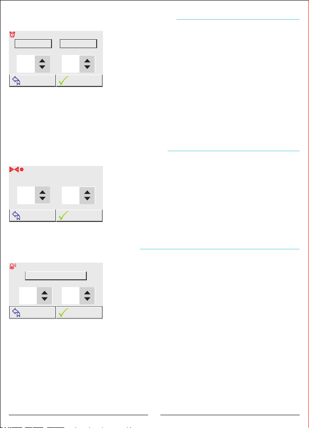
In this page inductive/active and capacitive/active Alarm
mode can be made passive or active and inductive/active and
capacitive/active ratio can be set. When the setting is active
color of the button's writing becomes green, when it is
passive it becomes red. When the ratios rise above the
activated set value, the display shows "High Inductive" or
"High Capacitive" warning. Also ''ALR1''is on. When the
Alarm mode is passive, the display doesn't show warning.
Pressing the ''Confirm'' button, the saved data is recorded and returns to ''Settings'' page.
When the ''Return'' button is pressed, without recording any value, turns to ''Settings'' page.
Settings E
1
Inductive Set %
Settings E
High Temperature
3.7 Compensation Target Setting
Enter the Target Ratios!
Capacitive Set %
05
TURN BACK
10
OK
3.8 Temperature Control
Temperature Protection Settings
Temperature Control Mode Active
Low Temperature
-1030
TURN BACK
OK
In this page, the inductive/active and capacitive/active
ratio that the device is aiming at compensation can be set.
Pressing the ''Confirm'' button, the saved data is recorded
and returns to ''Settings'' page. When the ''Return'' button is
pressed, without recording any value, turns to ''Settings''
page.
In this page Temperature control mode can be made
passive or active, High Temperature and low Temperature
values can be set. When the setting is active color of the
button's writing becomes green, when it is passive it
becomes red. When the Temperature control mode is active
if Set Temperature get out of upper and lower limits, the
display will show "High Temperature " or "Low Temperature"
warning. Also ''ALR2''is on.
Pressing the ''Confirm'' button, the saved data is recorded and returns to ''Settings'' page.
When the ''Return'' button is pressed, without recording any value, turns to ''Settings'' page.
12
Page 17
Settings E
Baudrate Modbus Address
19200
3.9 Modbus Settings
ModBus Settings - 8 N 1
001
TURN BACK
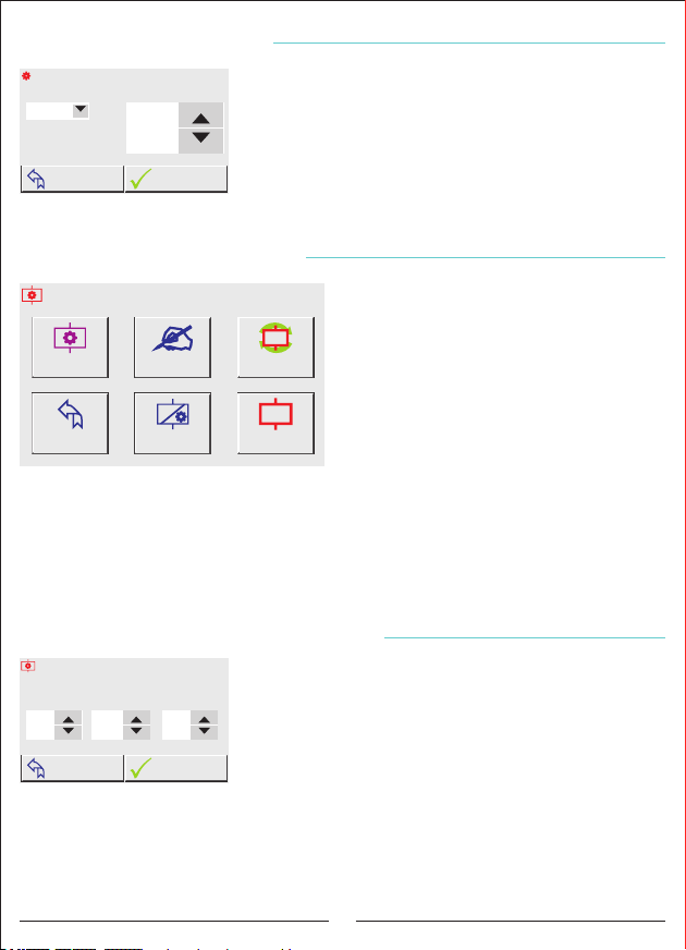
In this page remote communication settings can be done to
the device. Addresses of Baudrate and Modbus can be
changed. Databits=8, Stopbits=1 and Parity=none values are
fixed.
Pressing the ''Confirm'' button, the saved data is recorded
OK
and returns to ''Settings'' page. When the ''Return'' button is
pressed, without recording any value, turns to ''Settings''
page.
Settings E
3.10 Step Settings Page
Step Settings
When the Stage Button is pressed, Stage
Settings page comes to the screen in the
dynamic area. Times related to steps, Enter
Stage Value, Automatical Measurement, PFC
Settings, Stage Test and Settings Page can be
passed from this page.
Time Settings
Enter
the Steps Value
n
Auto Measurement
TEST
Back
Settings Page
PFC Settings
Step Test
3.10.1 Times: Drive, Discharge and Settling Times are set.
3.10.2 Enter Step Value: Value of step is entered manually
3.10.3 Automatical Measurement: The selected steps are measured.
Back Settings Page: Returns to the Settings page.
3.10.4 PFC Settings: Compensation can be active or passive mode.
3.10.5 Stage Test: The selected steps are checked.
Settings E Step Settings E
Step Time Settings
Drive
Time (sn)
Discharge
Time (sn)
04
Settling
Time (msn)
15
0400
3.10.1 Step Times
In this page, the intervention time, the capacitor discharge
time and the capacitor settling time can be set.
Drive time: it is the İntervention (Step taking-drop) time of the
device to the power change in the system.
Discharge time: It is the delay time of re-commissioning the
TURN BACK
OK
same step after dropping the capacitor in the step.
Step settling time: When a few steps are needed is the delay time between steps.
Pressing the ''Confirm'' button, the saved data is recorded and returns to ''Settings'' page.
When the ''Return'' button is pressed, without recording any value, turns to ''Settings'' page.
13
Page 18
Settings E Step Settings E
Enter the Step Value!
Step01PhaseL1Value (kVar)
-01.00
1.Step L1 Value was Saved!
TURN BACK
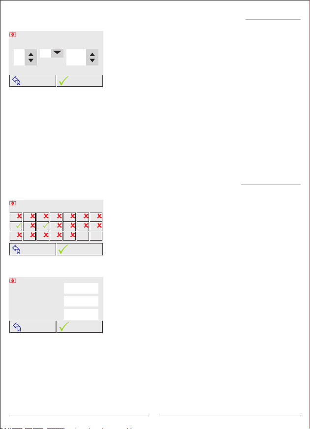
3.10.2 Entering the Manual Step Value
In this page, manual step value can be entered. Mono and
three phase capacitor or shunt reactor values can be entered.
Step, Phase and Values are set to help with the up and
down arrow buttons. The values entered by pressing the
"Confirm" button are saved and the writing comes to the
OK
related screen as "1. Stage L1 Value Registered!".
If the value to be entered is mono phase, select "L1, L2 or L3" from the phase section
according to the phase to which it is connected. "L123" should be selected for the three
phases.
Example: The value entered in the display is 1kvar capacitor in L1 phase and Step 1.
When the ''Return'' button is pressed, without recording any value, turns to ''Settings'' page.
Settings E Step Settings E
Select the Steps to Be Measured!
1
15 TCR
928
16
3
10
17
TURN BACK
4
11
18
3.10.3 Automatic Level Measurement
In this page, step is measured automatically.
765
Measurement could be done automatically only at chosen
141312
All
All
Pass
step. If you press the button of the step you desired, logo of
Active
the step will change. According to the Page 8th and 10th
START
steps are chosen for the automatic measurement. After
choosing the steps, automatic measurement starts when the
''start'' button is pressed.
CANCEL
1. Step (kVAr)
L1
-01.50
L2
-01.50
L3
-01.50
When the ''Return'' button is pressed, without recording
any value, turns to ''Settings'' page.
When the automatic step measurement is started, a page
comes to the screen like on the side. In the page it could be
OK
seen which measurement of the step is done and phases of
Step Measurement
Step Test Was Started
the measured value is shown separately. If the condenser is connected to the step, (-) sign is
seen on the left. If the shunt reactor is connected to the step, the value does not have a sign.
The chosen steps will be measured subsequently and when the measurement is finished
press ''confirm'' button in order to record values.
When the ''cancel'' button is pressed, measurement of the step is canceled and
measured values returns to the automatic step measurement screen without recording.
14
Page 19
Settings E Step Settings E
Choose the PFC Mode!
PFC Active
TCR Passive
TURN BACK
Step Counter
01
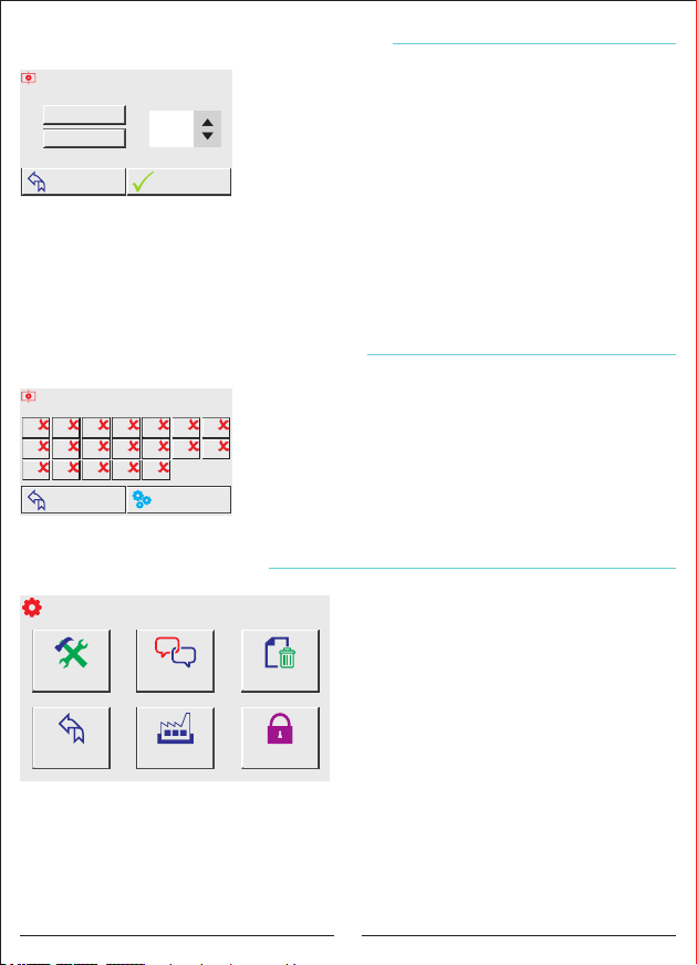
3.10.4 PFC Setting
In this page PFC(compensation) and TCR(SVC) are made
active or passive ,from the Step Counter part,the setting of
the device on how many steps can be included is done. The
device can disable PFC (compensation) in necessary (like
manuel usage) situations. When the PFC is passive,
the device gives up intervening to the system. In this situation,
OK
the device only makes measurement.
When the TCR(SVC) is deactivated, the device starts to make compensation as normal
reactive relay. Intervention can not be done with shunt reactor driver.
When the ''cancel'' button is pressed, measurement of the step is canceled and
measured values returns to the automatic step measurement screen without recording.
Settings E Step Settings E
Select the Steps to Test!
1
15 TCR
Ayarlar E
4
3
11
10
928
18
17
16
TURN BACK
3.11 Device Settings
Device Settings Page
Device Setup
TR
Language Options
3.10.5 Step Test
765
141312
SETTINGS
ENG
In this page step test is made manually. Control of the
step's output(like connection etc.) can be done. Chosen
steps are made active and the steps are on.
When the ''Return'' button is pressed, ''step setting'' page
comes to the screen; when the Setting button is pressed
''setting page comes.
When the Device Setting button is pressed,
Device Setting page comes to the dynamic
screen. You can pass Device Setup, Language
Choice, Deleting the Recordings, Factory
Delete Records?
Settings, Password Menu and Settings from
this page.
Back
Settings Page
Factory Settings
Password Page
3.11.1 Device Setup: Current Transformer Test and Automatic Step Measurement Operation
3.11.2 Language Options : Language settings of the device are changed.
3.11.3 Delete the Recordings : Data which are taken automatically by the device are deleted.
Back Setting Page : Returns to the settings page
3.11.4 Factory Settings: Factory or Menu settings, assumed values are returned.
3.11.5 Password Page: Password protection is assigned to the device.
15
Page 20
Settings E Step Settings E
Enter the CT Ratio
/5A
0150
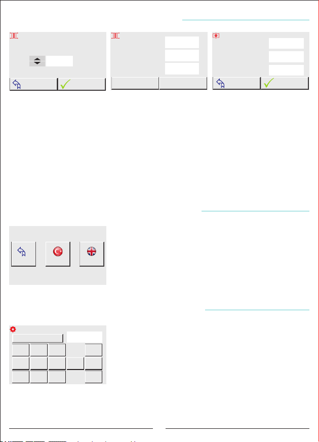
3.11.1 Device Setup
Current Transformer Test
CT Test was Started
OKTURN BACK
Cancel
CT Test
Current
L1
380.0
L2
380.0
L3
380.0
Confirm
CT Connection
A
Step Test Was Started
A
A
Step Measurement
CANCEL
1. Step (kVAr)
L1
-01.50
L2
-01.50
L3
-01.50
OK
In order to set the device press the ''up'' and ''down'' buttons, enter the current
transformer value. When you press ''confirm'' button the device starts current transformer
test automatically; after completing the test if any matter is available; the device gives
warning with connections.
If there is no matter in the connections, after completing the current transformer test;
the device start the step measurement automatically. When the device measured all of the
steps, if the ''confirm'' button is pressed, all of the steps are recorded. When the ''cancel''
button is pressed; the device cancels the step measurements and returns to ''Automatic
Measurement'' screen without recording the step measurements. After completing the step
measurement; the device starts to compensation according to the recorded values.
Settings E Step Settings E
3.11.2 Language Options
Language Selection
In this menu, The language settings of the device are
changed as Turkish or English. When you click to the
language you desired, the language of the device changes
Back
Settings Page
and turns to device setup page.
ENGLISHTÜRKÇE
When the ''Back'' button is pressed, ''Device Setup'' page
comes to the screen.
Settings E Step Settings E
Password Menu
Password Control Passive
1
4
7
Enter New Password!
2580
2
3
5
690
8
3.11.3 Password Settings
In this page control of the password becomes active, the
device can be protected against the unauthorized intervention.
After the control of the password is made active ;entered
Del
password value is recorded. the password consist of 4 letters.
Cancel
You can enter the password pressing the numbers. When the
password is entered, press ''confirm'' button to record
OK
password. When you quit from the setting menu; the device
is protected anymore.
When the ''Return'' button is pressed, it turns to the ''Setting'' page without doing
operation.
16
Page 21
Settings E Step Settings E
Select the Record You Want to Delete
SN: 12345678
Ver: 1.09
Back
Settings Page
kWh
kVArh
Delete Total
Energy Record
Q Q
P
Delete Reactive
Ratios
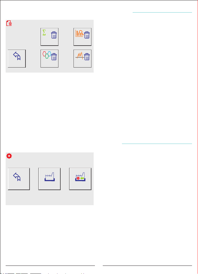
3.11.4 Delete The Recording
When the "Delete Registration" button is
pressed, the dynamic area screen displays the
Register Delete page. In this page, the total
energy values, power analysis examples,
Delete Power
Analysis Samples
Ratio and Demand values that the device
automatically receives are deleted. The device
serial number and software version are
included.
Delete Demands
Delete Total Energy Values:Deletes total
energy values (Active, Inductive, Capacitive).
Delete Power Analysis Samples: Deletes the sample records of the power analysis.
Back Settings Page: Returns to the Settings page without performing any operation.
Delete Ratios: Deletes Capacitive/Active and Inductive / Active ratios.
Delete Demands: Deletes Active Power, Reactive Power, Apparent Power and Current
Demand.
Press the record button you want to delete. Then the confirmation message box will come
up again. If you press the "confirm" button here, the record will be deleted. If you press the
"cancel" button. It returns without deleting the records.
When you press the "Back Settings Page" button, the main page of the device setup is
displayed.
Settings E Step Settings E
Factory Settings
3.11.5 Factory Settings
When the Factory Setting button is pressed,
factory settings main page comes to the
dynamic screen. In this page all values of the
device are expected to return factory settings
or only menu values can be provided to return
factory values.
Note: Returning to the factory settings
necessitates the device to be set up again.
Back
Settings Page
MENU
Load Menu
Settings
Load Factory
Settings
(Current transformer value, step value, menu
settings etc. All values and records will be
reset.)
Note: Returning to the menu settings does not require the device to be reinstalled.
(Harmonic Voltage, Harmonic Current, Step Times, Generator, Voltage Min / Max, Alarm,
Compensation Target Values, Temperature and Modbus Settings will be reset.)
Press the button you want to return to the old settings. Then the confirmation message
box will come up again. If you press the "confirm" button on this page, the relevant settings
will return to the old factory values. If you press the "cancel" button, it exits without doing
anything.
When you press the "Back Settings Page" button, the main page of the device setup is
displayed.
17
Page 22
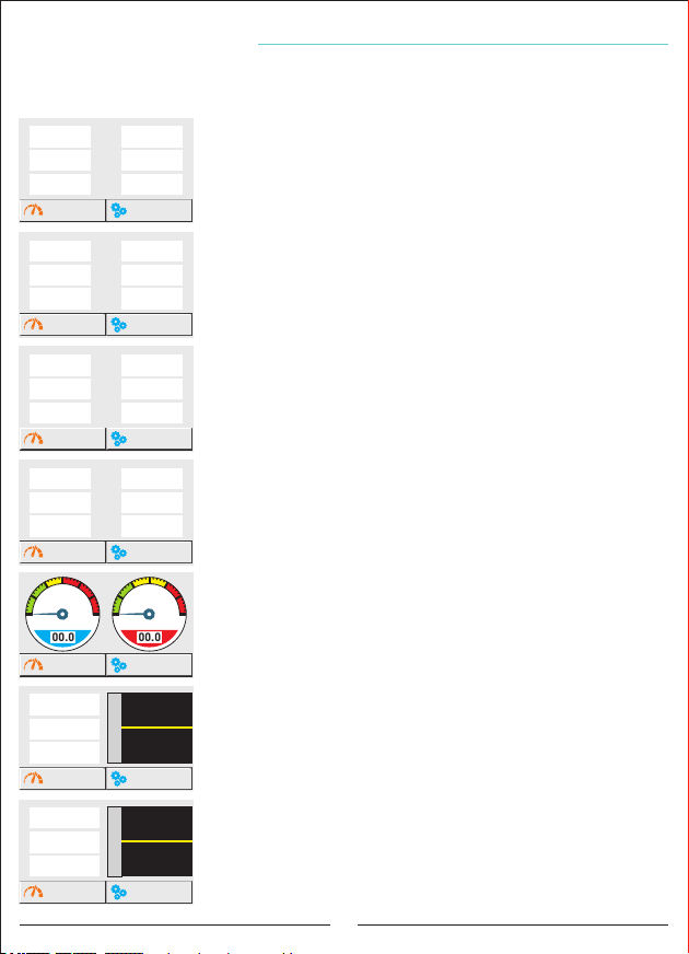
How to Choose a Main Page?
The home page is the page that will appear on the dynamic display when the device is
energized and will remain visible without pushing the buttons. You can define the main page
you want to see continuously from the following measurement pages.
Voltage L-N
L1 L12
220.0
L2
220.0
L3
220.0
MEASUREMENTS
Voltage L-N
L1 L1
220.0
L2
220.0
L3
220.0
MEASUREMENTS
Voltage L-N
L1 L1
220.0
L2
220.0
L3
220.0
MEASUREMENTS
Active Power (KW)
L1 L1
0.000
L2
0.000
L3
0.000
MEASUREMENTS
10
5
0
Capacitive/Active R. (%)
00.0
MEASUREMENTS
Power Factor
L1
-0.999
L2
-0.999
L3
-0.999
MEASUREMENTS
Cosinus ( COS )
L1
-0.999
L2
-0.999
L3
-0.999
MEASUREMENTS
Voltage L-L
V
380.0
L23
V
380.0
L31
V
380.0
Current
V
1.358
L2
V
1.453
L3
V
1.289
Frequency
V
50.00
L2
V
50.00
L3
V
50.00
Reactive Power (kVAr)
0.000
L2
0.000
L3
0.000
15
20
10
5
25
30
0
Inductive/Active R. (%)
00.0
1.00
0.00
Power Factor
-1.00
1.00
0.00
Cosine
-1.00
To select the voltage page as the home page, after the
V
“measurements” button is pushed, the dynamic screen displays
V
Voltage page comes to the Dynamic page. If it does not switch to
V
another page for 15 minutes, it is defined as the main page.
SETTINGS
To select the voltage and current pages as the home page, after
A
the “measurements” button are pushed, the dynamic screen
A
displays . From this page, press the measurement page1
A
Dynamic page. If it does not switch to another page for 15 minutes,
SETTINGS
it is defined as the main page.
To select the voltage and frequency pages as the home page,
Hz
after the “measurements” button are pushed, the dynamic screen
Hz
displays . From this page, press the measurement page1
Hz
to the Dynamic page. If it does not switch to another page for 15
SETTINGS
minutes, it is defined as the main page.
. From this page, press the button. measurement page1 1.1 Voltage
button. Voltage- current page comes to the 1.2 Voltage& Current
button. Voltage- Frequency page comes 1.3 Voltage& Frequency
To select the Instant powers pages as the home page, after the
“measurements” button are pushed, the dynamic screen displays
. From this page, press the measurement page1
button. Instant powers page comes to the 1.4 Instant powers
Dynamic page. If it does not switch to another page for 15 minutes,
SETTINGS
it is defined as the main page.
15
20
To select the Ratios pages as the home page, after the
25
“measurements” button are pushed, the dynamic screen displays
30
. From this page, press the button. measurement page1 1.5 Ratios
Ratios page comes to the Dynamic page. If it does not switch to
another page for 15 minutes, it is defined as the main page.
SETTINGS
To select the Power Factor pages as the home page, after the
“measurements” button are pushed, the dynamic screen displays
. From this page, press the measurement page1 1.6 Power Factor
button. Power factor page comes to the Dynamic page. If it does
not switch to another page for 15 minutes, it is defined as the main
SETTINGS
page.
To select the Cosine pages as the home page, after the
“measurements” button are pushed, the dynamic screen displays
. From this page, press the button. measurement page2 2.3 Cosine
Cosine page comes to the Dynamic page. If it does not switch to
another page for 15 minutes, it is defined as the main page.
SETTINGS
18
Page 23
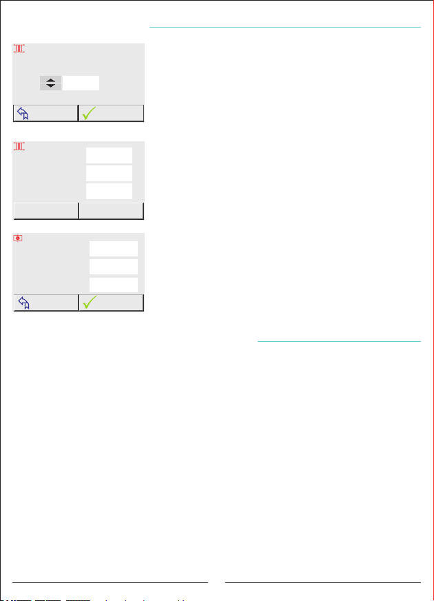
How to Install the Device?
Enter the CT Ratio
To access the device setup page, enter the following
menus, respectively;
0150
/5A
Ayarlar E
Device SettingsE
Device Setup E
After reaching the device setup page, press the up or down
buttons to enter the current transformer value. When the
OKTURN BACK
"Confirm" button is pressed, the device automatically starts
Current Transformer Test
CT Test was Started
Cancel
CT Test
Step Measurement
Step Test Was Started
CANCEL
Current
L1
380.0
L2
380.0
L3
380.0
CT Connection
1. Step (kVAr)
L1
-01.50
L2
-01.50
L3
-01.50
Confirm
the current transformer test. If there is any trouble in the
connections after the current transformer test is finished,
A
the device will give a warning and will not accept the
A
connection. After correcting the connection errors according
to the warning, you can start the device installation again.
A
If there is no problem with the connections, the device will
automatically start to measure the Step after the current
transformer test is confirmed. After the device has measured
all the steps, pressing the "Confirm" button saves all
measured steps and the device starts to intervene.
When the "Cancel" button is pressed, it will cancel and
returns to the "Automatic measurement" screen without
OK
saving the step measurements.
How to Change the Current Transformer Value?
To reach the current transformer value change page, enter the following commands
respectively;
Settings E
Current Transformer EChange Current Transformer Ratio E
After reaching the Change current transformer page (Figure 1), press the up and down
buttons to enter the current transformer value. When the "Confirm" button is pressed, the
device automatically starts the current transformer test (figure 2) if there is any trouble in
the connections after the current transformer test is finished, the device will show the
warning and will not accept the connection. After correcting the connection errors according
to the warning, you can start the current transformer test again.
If there is no problem with the connections, the device will automatically start to measure
the Step after the current transformer test is confirmed (figure 3). After the device has
measured all the steps, pressing the "Confirm" button saves all measured steps and the
device starts to intervene.
When the "Cancel" button is pressed, it will cancel and returns to the
"Automatic measurement" screen without saving the step measurements.
19
Page 24
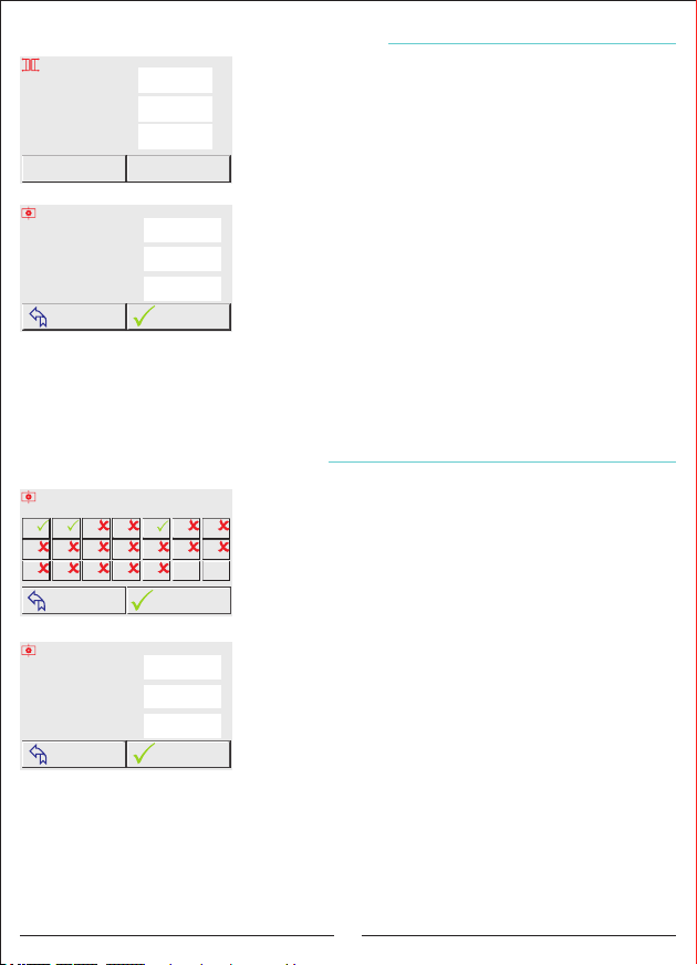
How is the Current Transformer Test Done ?
Current Transformer Test
CT Test was Started
Cancel
CT Test
Step Measurement
Step Test was Started
CANCEL
Current
L1
380.0
L2
380.0
L3
380.0
CT Connection
1. Step (kVAr)
L1
-01.50
L2
-01.50
L3
-01.50
Confirm
In order to reach current transformer test page, enter
A
these menus subsequently;
A
Settings E
A
After reaching the current transformer page, when the
Current TransformerE
Start CT Test E
''Start Current Transformer Test'' button is pressed, the test
starts automatically. If any kind of error happens in the
connections, the device gives warning and does not accept
the connection. After canceling the test, you can start current
transformer test, just after correcting the connection error
according to the warnings.
If there is no error in the connections, the device starts step
OK
measurement automatically after the current transformer
test is confirmed. After the device measured all steps, when
the ''confirm'' button is pressed all of the measured steps are recorded and the device
starts intervention.
When the "Cancel" button is pressed, it will cancel and returns to the
"Automatic measurement" screen without saving the step measurements.
How is the Step Measurement Done?
Select the Steps to Be Measured!
1
15 TCR
928
16
3
10
17
TURN BACK
4
11
18
In order to reach step measurement (automatic
measurement) page, enter these menus subsequently;
765
Settings E
141312
All
All
In order to choose the steps which is to be measured in the
Pass.
Active
automatic measurement page; press the button of the step.
OK
When the button is pressed; logo of the step is changed.
Step Settings E Auto Measurement E
After choosing the steps, when the ''Start'' button is pressed;
Step Measurement
Step test was Started
CANCEL
1. Step (kVAr)
L1
-01.50
L2
-01.50
L3
-01.50
automatic measurement starts.
When the step measurement starts, step measurement
page comes to the screen. The page shows which
measurement of the step is done and the value that is
measured at each phase. If the capacitor is connected,
OK
(-) sign appears on the left. If the shunt reactor is connected,
there is no sign of the value. After the measurement of the
step is completed, subsequent step measurement starts if there is chosen steps. When the
measurements completed ''step test is completed'' sign comes to the screen . Press the
''confirm'' button in order to record values. When you press the ''confirm'' button ;
''step measurement is confirmed'' sign comes to the screen and turns to the main page and
the device start to interfere.
If you press the ''return'' button, main page of the step comes to the screen without doing
any operation.
20
Page 25
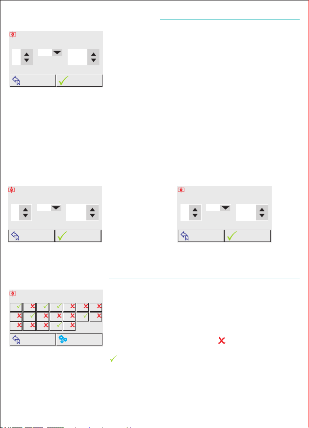
How is the Step Value Entered Manually?
Enter the Step Value!
Step01PhaseL1Value (kVar)
-1.00
1. Step L1 Value was Saved!
TURN BACK
In order to reach ''Enter Step Value'' page, enter these
menus subsequently;
Settings E
Step Settings E
Enter the Steps Value E
After reaching the Enter Step Value page; Step, Phase, and
Values are set pressing ''up'' and ''down'' buttons. Then the
OK
values are recorded pressing the ''Confirm'' button and
''1. Step L1 Value was Saved!'' sign comes to the screen.
Ex: Capacitor value is entered to the 1st step at the L1 phase
If the value to be entered is mono phase, from the phases section ''L1,L2 or L3''should be
chosen according to the phase which is connected to; if it is three phase ''L123'' should be
chosen.
Note: If the condenser will be added to the system, the value to be entered should be
''-'' (picture6); if the shunt reactor is to be added ,the value to be entered should be
''+'' (picture7).
Capacitor
Enter the Step Value!
Step02Phase
L123
Value (kVar)
-10.00
Shunt Reactor
Enter the Step Value!
Step03PhaseL3Value (kVar)
+1.50
TURN BACK
OK
3 phase 10kVar capacitor value
entered to the 2nd step.
TURN BACK
1.5kVar shunt reactor value
entered to the 3rd step at the L3 phase.
OK
How is The Step Test Done?
Select the Steps to Test!
1
15 TCR
928
16
3
10
17
TURN BACK
4
11
18
In order to reach the step test page ,enter these menus
subsequently;
SettingsE
765
141312
All of the steps will be apparent on the screen; after
reaching Step Test Page. Touching the step; it is pulled and
SETTINGS
left back. If the logo of the step is ''red x'' ; when Quit the
Step Settings E
Step Test E
Step button is pressed, logo of the step becomes
green thick and gives Quit. When we press the same step
button again, the logo changes and the steps don't give quit.
If ''the Return'' button is pressed; step main page comes to the screen by abandoning
steps one by one.
21
Page 26
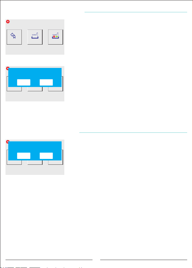
How to Return to Factory Settings?
Factory Settings
In order to return Factory Settings page, enter these
menus subsequently;
Back
Settings Page
MENU
Load Menu
Settings
Settings E
Load Factory
Settings
After reaching the Factory Settings page when
Device Settings E
Factory SettingsE
''Load Factory Settings'' button is pressed; “Load Factory
Settings? '' message box come to the screen and when the
''Accept'' button is pressed; the device returns to
Factory Settings
Load Factory Settings?
ACCEPT CANCEL
Back
Settings Page
MENU
Load Menu
Settings
Factory Settings.
When the ''Cancel'' button is pressed on the message box,
it returns to Factory Setting page without doing operation.
Load Factory
Settings
Note: Restoring the factory settings requires reinstallation!
(Current transformer value, step values, menu settings, etc.
all values and records will be reset.)
How to Return to Menu Settings?
Factory Settings
Load Menu Settings?
ACCEPT CANCEL
Back
Settings Page
MENU
Load Menu
Settings
In order to return Factory Settings page,enter these menus
subsequently;
SettingsE
Load Factory
Settings
After reaching the Factory Settings page when
Device Settings E
Factory Settings E
''Load Menu Settings'' button is pressed; “Load Menu
Settings? ''Message box come to the screen and when
the ''Accept'' button is pressed; the device returns to Menu
Settings.
When the ''Cancel'' button is pressed on the message box, it returns to Factory Setting page
without doing operation.
Note: (Harmonic Voltage, Harmonic Return to the Menu settings requires reinstallation!
Current, Step Times, Generator, Voltage Min / Max, Alarm, Compensation Target Values,
Temperature and Modbus Settings will be reset.)
22
Page 27
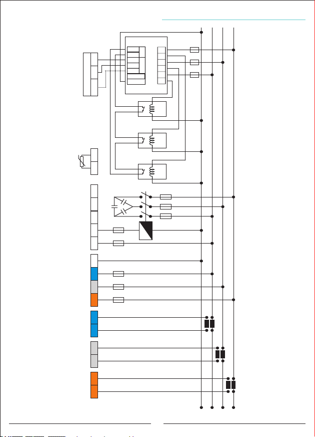
Three Phase (3P4W) Connection Scheme
OUT
IN
AB
SVC CON
SGND
THERMAL
B A
GND
SVC CON
N
T3 L3
T2 L2
T1 L1
R1
NTC
Thermal Conenctions
GND
NTC
C18
-
-
C1
L
N
L1L2
L3
l1k1l2k2
l3k3
R2
R3
3A
10A
2A2A2A
Contactor
S2
P2
C.T.1
P1
S1
S2
P2
C.T.2
P1
S1
S2
P2
C.T.3
P1
S1
N
L1
L2
23
L3
Page 28
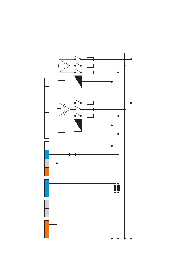
Single Phase Connection Scheme in Three Phase Systems
It is not recommended to use single-phase compensation for three-phase systems.
The device intervenes only with single phase. It is not known how this intervention will result
in the other two phase
This connection should be preferred after ensuring that the three-phase system is
balanced. Check the index values in the counter more frequently.
C18
- - - -
3A 3A
C1
LN
10A
L1L2
L3
l1k1l2k2
l3k3
2A
Contactor
Contactor
S2
P2
C.T.
P1
S1
N
L1
L2
L3
24
Page 29
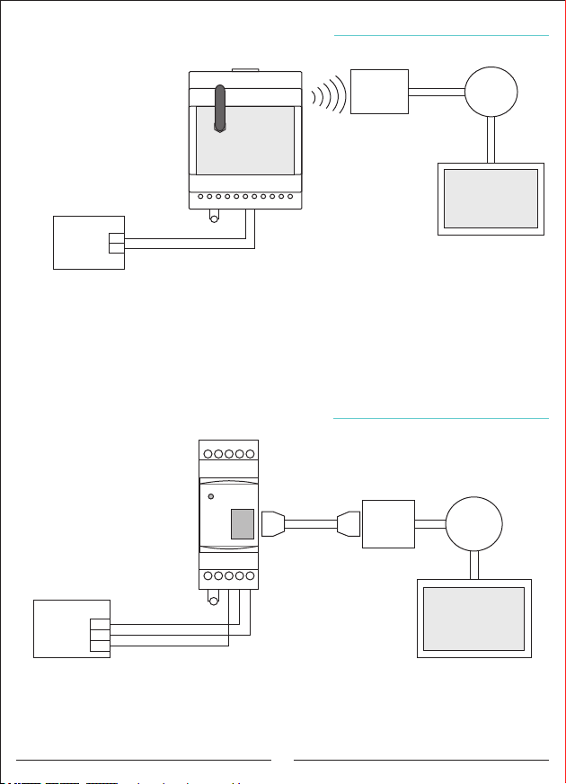
Remote Communication with RS485 (GSM-MOD)
Operatör
Internet
/ Server
GSM-MOD
PC - Computer
PFC
Relay
RS485
A1
A2
A
B 5V
TX RX
~
220V
A
B
AC
GND
Only reactive relay or together with counter and energy analyzer can be connected with
GSM-MOD on remote communication. Using a 100MB (recommended) data line from GSM
operators, remote communication is made with reactive relay via www.tenseenerji.com
(server).
Remote Communication with RS485 (ETH-MOD)
PFC
Relay
RS485
GND
ETH-MOD-T
GND
A2 A B
A1
~
220V
A
B
AC
RJ-45
Connector
Ethernet Cable
RJ-45
Connector
ADSL
Router
Internet
/ Server
PC - Computer
Only reactive relay or together with counter and energy analyzer can be connected with
GSM-MOD on remote communication. Remote connection is made with reactive relay via
www.tenseenerji.com (server) by connecting modem.
25
Page 30
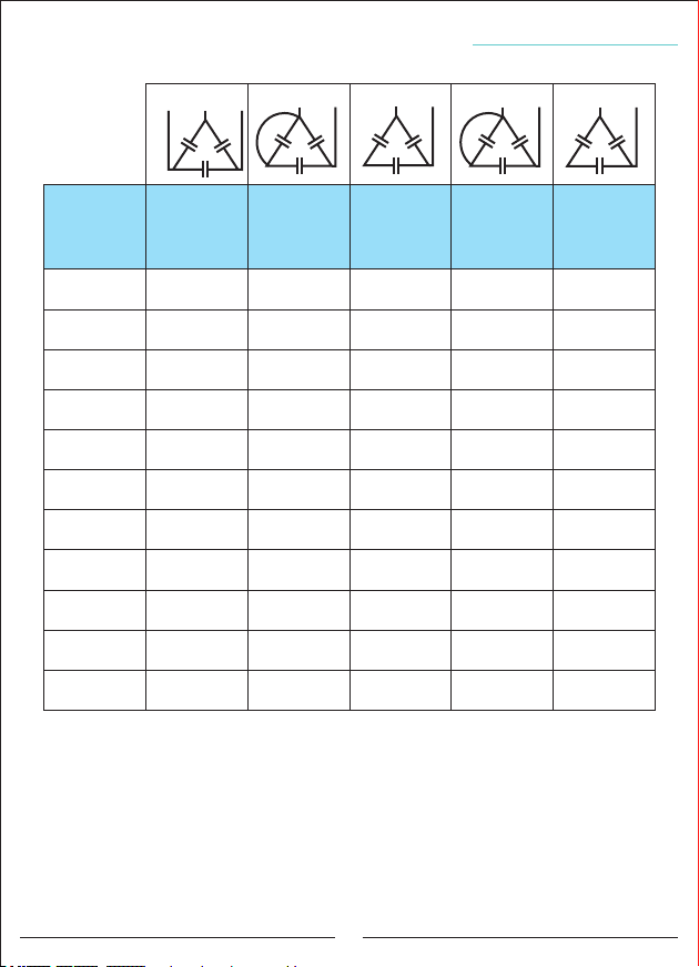
Capacitor Account Table according to Connection Type
T
S
T
R
S
S
T
N
S
S
N
Capacitor
Power
0,5 KVAR
1 KVAR
1,5 KVAR
2,5 KVAR
5 KVAR
7,5 KVAR
10 KVAR
15 KVAR
20 KVAR
25 KVAR
30 KVAR
3 Phase
Connection
(Q/3)
0,16 KVAR
0,33 KVAR
0,5 KVAR
0,83 KVAR
1,66 KVAR
2,5 KVAR
3,33 KVAR
5 KVAR
6,66 KVAR
8,33 KVAR
10 KVAR
2 Phase
Connection
Bridge
(Q/3)
0,16 KVAR
0,33 KVAR
0,5 KVAR
0,83 KVAR
1,66 KVAR
2,5 KVAR
3,33 KVAR
5 KVAR
6,66 KVAR
8,33 KVAR
10 KVAR
2 Phase
Connection
(Q/4)
0,12 KVAR
0,25 KVAR
0,37 KVAR
0,62 KVAR
1,25 KVAR
1,87 KVAR
2,5 KVAR
3,75 KVAR
5 KVAR
6,25 KVAR
7,5 KVAR
Phase-Neutral
Bridging
Connection
(2xQ/9)
0,11 KVAR
0,22 KVAR
0,33 KVAR
0,55 KVAR
1,11 KVAR
1,66 KVAR
2,22 KVAR
3,33 KVAR
4,44 KVAR
5,55 KVAR
6,66 KVAR
Phase-Neutral
Connection
(Q/6)
0,08 KVAR
0,16 KVAR
0,25 KVAR
0,41 KVAR
0,83 KVAR
1,25 KVAR
1,66 KVAR
2,5 KVAR
3,33 KVAR
4,16 KVAR
5 KVAR
26
Page 31
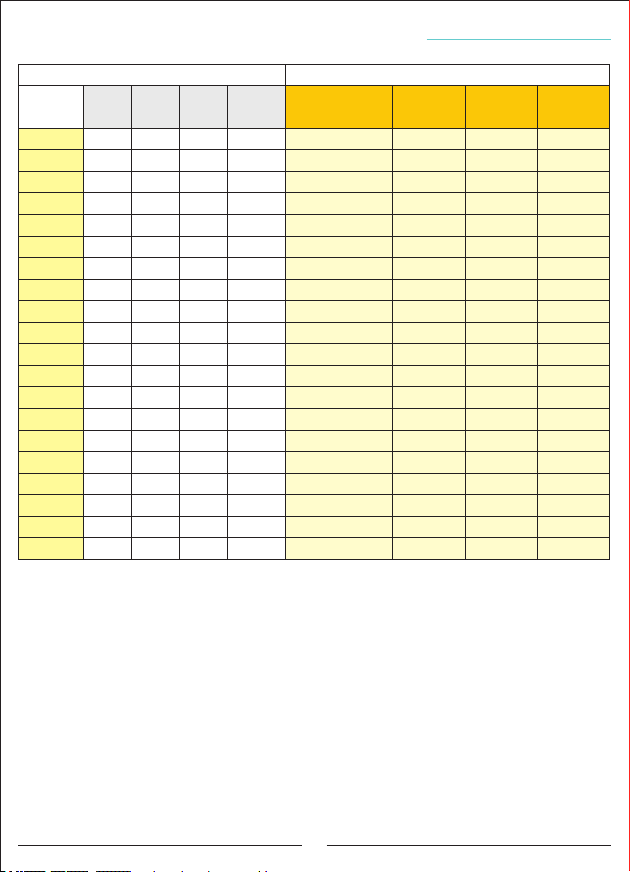
Step Creation According to Power Analysis Examples?
1.Sample
2.Sample
3.Sample
4.Sample
5.Sample
6.Sample
7.Sample
8.Sample
9.Sample
10.Sample
11.Sample
12.Sample
13.Sample
14.Sample
15.Sample
16.Sample
17.Sample
18.Sample
19.Sample
20.Sample
Table1 Table2
L1
0.00
0.00
2.00
0.75
1.50
0.50
0.20
0.80
0.30
2.40
3.20
2.50
2.70
0.50
0.00
0.35
2.50
3.20
3.00
2.70
L2
0.00
1.00
1.50
1.00
1.80
2.00
1.50
0.00
0.40
3.50
4.00
4.50
2.90
1.00
-0.10
1.00
0.50
4.70
4.20
0.50
(min.)
1.50 -
571
1.50
525
0.50
490
1.50
470
453
1.00
2.50
400
1.90
385
0.50
350
0.35
300
4.50
295
1.50
280
1.90
257
3.20
236
1.50
205
0.50
192
1.70
180
1.50
120
5.50
100
2.50
70
1.50
45
Time
L3
Threephase
Capacitor
(kvar)
1.50
2.50
3.00
1.50
0.50
1.00
7.50
5.00
6.00
8.00
1.50
1.00
1.50
10.0
7.50
1.50
Monophase (L1)
-
-
-
-
Capacitor
(kvar)
-
1.50
-
0.50
-
-
0.80
-
-
1.60
0.50
-
-
-
-
2.00
-
0.50
2.20
Monophase (L2)
Capacitor
(kvar)
-
1.00
1.00
0.20
0.80
1.50
1.30
-
0.05
1.00
2.30
2.5
0.20
0.50
-
0.65
-
1.30
1.70
-
Monophase (L3)
Capacitor
(kvar)
1.50
1.50
-
0.70
-
2.00
1.70
0.50
-
2.00
-
-
0.40
1.00
0.50
1.35
1.00
2.10
-
1.00
In the Table 1; artificial samples are created. In Table 2 ; three phase and one phase
samples which can be used through these samples are created. While step structures are
being created; the interval values should be interfered. Replace highest three phase
capacitor values to the first steps.
Lowest 0.5 kvar and highest 10 kvar are available in three phase capacitors.
0.5kvar, 1kvar, 2.5kvar, 5kvar, 7.5kvar three phase capacitor can be used.
Lowest 0.5kvar and highest 2.2kvar are available at one phase capacitors to be used at
L1 phase. 0.5kvar, 1kvar and 1.5kvar one phase capacitor can be used.
Lowest 0.20kvar and highest 2.3 kvar are available at one phase capacitors to be used at
L2 phase. 0.25kvar, 0.5kvar, 1kvar and 1.5kvar one phase capacitor can be used.
Lowest 0.40kvar and highest 2.1 kvar are available at one phase capacitors to be used at
L3 phase. 0.25kvar, 0.5kvar, 1kvar, and 1.5kvar one phase capacitor can be used.
27
Page 32
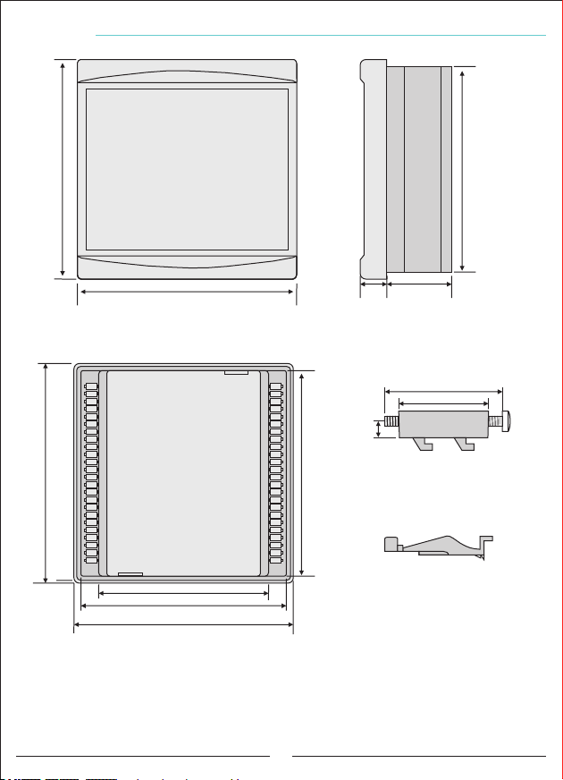
Dimensions
147mm
Front view
Left Side
View
138mm
147mm
147mm
Rear view
114.5mm
138mm
147mm
22mm
43mm
Screwed side ear (apparatus)
45mm
34mm
6mm
138mm
Side ear (apparatus)
28
Page 33
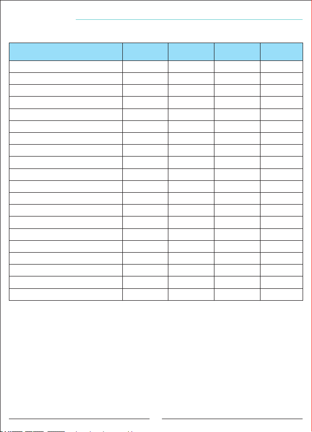
Factory Defaults
Setting Name
Current Transformer Ratio
Harmonic Voltage ( / )A P
Harmonic Voltage Delay
Harmonic Current ( / )A P
Harmonic Current Delay
High Voltage ( / )A P
Low Voltage ( / )A P
Inductive Alarm ( / )A P
Capacitive Alarm ( / )A P
Generator ( / )A P
Inductive Set
Capacitive Set
High Temperature ( / )A P
Low Temperature ( / )A P
Drive Time
Discharge Time
Settling Time
Baudrate
Modbus Address
Step Counter
Fixed Values:
Parity: none, Stopbits:1, Demand Time: 15min.
( / ): Can be active or passive.A P
Passive
Passive
Passive
Passive
Passive
Passive
Passive
Passive
Passive
Factory
Value
5/5
10
30
50
50
250
180
20
15
45
5
10
50
-10
2
15
400
9600
1
16
Minimum
Value
5/5
5
1
5
1
240
120
5
5
1
1
1
30
-20
1
1
100
2400
1
1
Maximum
Value
5000/5 A
99
60
99
60
285
200
50
50
50
50
50
70
10
15
30
2000
115200
247
18
Unit
%
sn.
%
sn.
V
V
%
%
%
%
%
°C
°C
sn.
sn.
msn.
bps.
29
Page 34
Technicial Features
Operating Voltage
Operating Frequency
Operating Power
Operating Temperature
Voltage Measuring Range
Current Measurement Range
Current Transformer Ratio
Voltage, Current Accuracy
Active Accuracy
Reactive Accuracy
Real Time Clock
Harmonic Voltage
Harmonic Current
Remote Connection Speed
Remote Connection Features
Remote Link Interface
Indicator
Connection Type
Contact
Number of Steps
Cable Diameter
Weight
Mounting
Operation Altitude
Protection Class
Panel Hole Dimensions
100V - 300V AC
50 / 60 Hz
<12VA
-20ºC.....+55ºC
5V -280V AC
5mA - 5,5A
5/5A........5000/5A
%±0,5
%±1
%±2
>5 years
2 - 61
2 - 61
2400, 4800, 9600, 19200, 38400, 57600, 115200bps
Databits.:8, Stopbits.:1, Parity:None
RS485 MODBUS RTU
5” resistive touch color LCD
Plug-in terminal connection
3A / 250V AC Resistive Load
18 + TCR
1.5mm², 2.5mm² (voltage inputs)
<900Gr.
Mounting on the front of the panel
<2000meters
IP41 (Front Panel), IP00 (Body)
140mm x 140mm
Contact Informations
Web: www.tense.com.tr
Mail: [email protected]
Merkez Mah. Akalar Sok. No:39A
GAZİOSMANPAŞA / İSTANBUL / TÜRKİYE
Tel: +90212 578 04 38 - 48 Fax: +90212 578 04 36
30
Page 35

User Notes
31
Page 36

QUALITY SOLUTIONS
ELECTRICITY – ELECTRONIC SAN.TİC.A.Ş
Rev:1.10_160713
Document number: DK-048-1
MADE IN TURKEY
 Loading...