

Tenor 350M Owner's Manual
Tenor
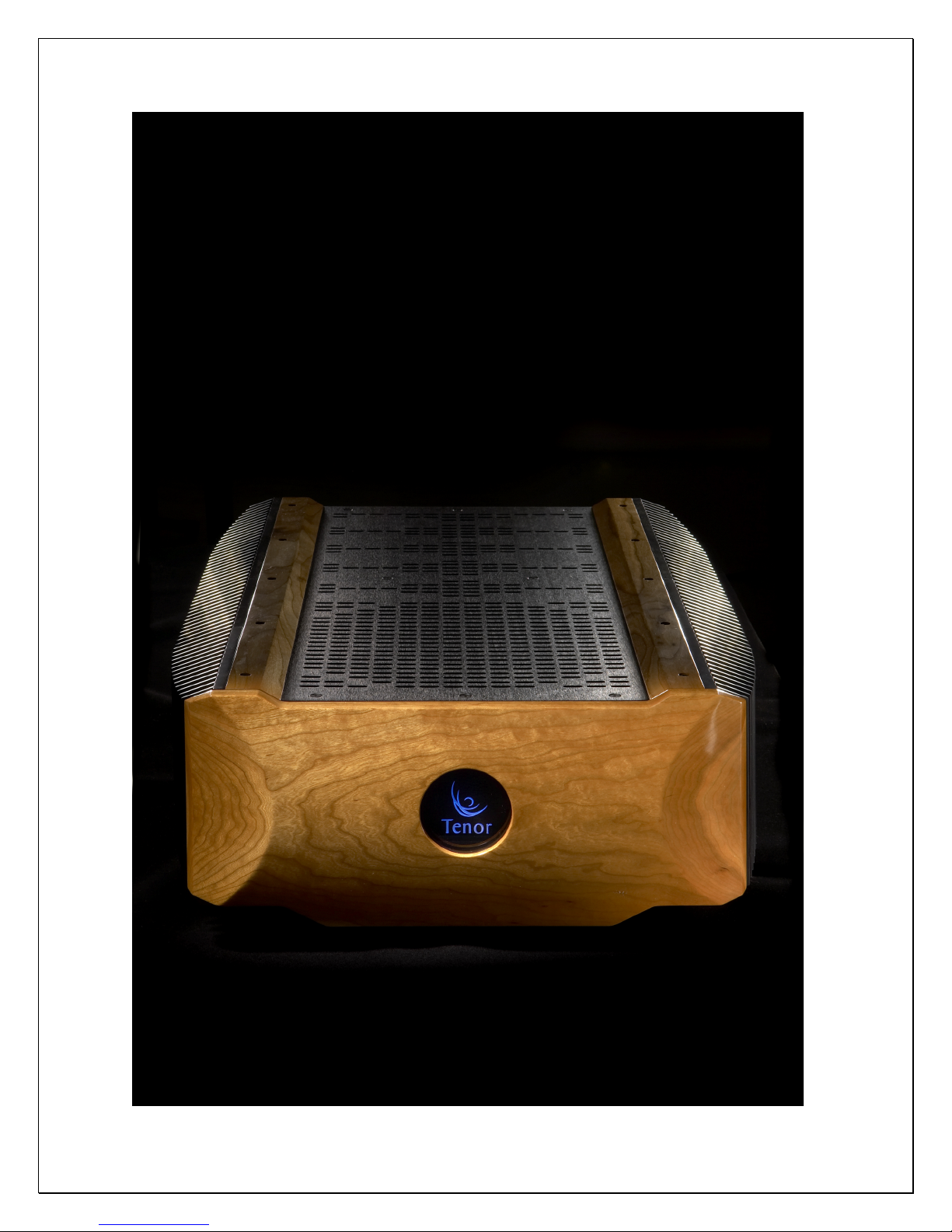
350M
Mono Blocks
Ultimate Reference Amplifier
Owner’s Manual
Te n or I nc.
Versio n: November 2008

2

3
Important Safety Instructions
• Please read this Owner’s Manual for your own safety and the protection of your Tenor
equip ment.
• Once you have installed your Tenor equipment, store this Owner’s Manual in a safe
place for future reference if necessary.
• Please heed all warnings.
• Please follow all instructions .
• Do not use this equipment near water or where there might be a chance it could come
in contact with water.
• Clean only with a clean dry cloth.
• Do not install near a heat source such as radiators, heat registers, stoves or any other
source of heat.
• Do not defeat the safety purpose of the polarized and/or grounding type plug. A polarized plug has two blades with one slightly wider than the other. A grounding plug
includes the third ground prong. In the event the plug provided does not fit your
power outlet, consult an electrician for assistance. Failure to do this may result in
damage to the equipment and/or possible injury or death.
• Please protect the power cord from being walked on or pinched, particularly at the
wall and at the plug on the rear panel of the equipment.
• The use of extension cords and/or convenience plugs is not advised due to the power
requirements of the equipment.
• Please mount equipment as specified in User Manual.
• Please unplug equipment during lightening storms and when not in u se for long peri-
ods of time.
• Refer all service of equipment to qualified personnel. In the event the equipment
has been damaged, dropped, exposed to water or foreign objects have entered the
cabinet, di sconnect im mediately from power source and consult a qualified service
techni cian.
WARNING: TO REDUCE THE RISK OF FIRE OR ELECTRIC SHOCK, DO NOT EXPOSE THIS APPLIANCE TO RAIN OR MOISTURE!
CAUTION: TO REDUCE THE RIS K OF ELECTRICAL SHOCK, DO NOT REMOVE COVER. NO
USER-SERVICEABLE PARTS INS IDE. REFER ALL SERVICING TO QUALIF IED PERSONNEL!

4
Table of Contents
Introduction ........................................................................................................6
Congratulations....................................................................................................................................... 6
Safe Set-up Instructions .................................................................................................................... 6
Design Principles ................................................................................................................................... 6
Precision Engineering & Assembly .............................................................................................6
Unpacking............................................................................................................ 7
Lifting Caution – 148lbs (67Kg)!.....................................................................................................7
Travel Cases................................................................................................................................................7
List of Items Included with pair of Tenor 350M.................................................................7
Moving Amplifiers..................................................................................................................................7
Installation ......................................................................................................... 8
Considerations ..........................................................................................................................................8
3rd Party Isolation Stands ...................................................................................................................8
Placement....................................................................................................................................................8
Ventilation ..................................................................................................................................................8
Source Components ..............................................................................................................................9
Speakers.......................................................................................................................................................9
Remote Turn On Jack.......................................................................................................................... 9
Power Requirements ........................................................................................ 10
AC Mains Voltage.................................................................................................................................. 10
Warm-Up ...................................................................................................................................................10
Mute Operation .....................................................................................................................................10
Break-in Period.......................................................................................................................................11
Tube Life....................................................................................................................................................11
Special Design Features .................................................................................. 12
Power Supply .......................................................................................................................................... 12
Audio Amplification..........................................................................................................................12
Protection.................................................................................................................................................12
Environmental Considerations .....................................................................................................13

5
Front Panel .......................................................................................................14
Front Panel Layout..............................................................................................................................14
On/Off Switch .......................................................................................................................................14
Front Lens – Indicator Light ...........................................................................................................15
Mute Switch .............................................................................................................................................15
Rear Panel & Internal View............................................................................. 16
Cautions .....................................................................................................................................................16
AC Mains On/Off & Fuse .................................................................................................................16
Remote Turn On Jack........................................................................................................................16
Single Ended and Balanced Inputs............................................................................................17
Loudspeaker Binding Posts ............................................................................................................ 17
350M Internal View ............................................................................................................................. 17
Troubleshooting & Protection Circuitry Overview........................................ 18
Internal Fuses Associated With Protection Circuitry................................................... 18
Other Internal Fuses........................................................................................................................... 18
Example Protection Scenarios ..................................................................................................... 19
No Audio + Front Panel Lens Light is Dark ....................................................................19
No Audio + Front Panel Lens Light is Blue.....................................................................19
No Audio + Front Panel Lens Light is Red (continuous) ........................................ 19
No Audio + Front Panel Lens Light is Red (flashing)...............................................20
Audio + Front Panel Lens Light turns briefly from Blue (normal) to Red 20
Ground Hum............................................................................................................................................20
Care and Maintenance ..................................................................................... 21
Wood Faceplate and Top Rails ....................................................................................................21
Metal Chassis and Top Plate.........................................................................................................21
Electrical Connections on Rear Plate......................................................................................21
Audio Board (Vacuum Tubes)....................................................................................................... 21
Tenor 350M Specifications ..............................................................................22
Warranty ........................................................................................................... 23
Product Registration ....................................................................................... 24
Tenor Contact Information..............................................................................25
Owner’s Notes.................................................................................................. 26

6
Introduction
Congratulations
Congratulations on the purchase of your new Tenor 350M Mono Blocks (Tenor 350M)
Ultimate Reference Amplifier. We are very proud of the extensive engineering, design and craftsmanship in our amplifiers and are confident that our Tenor 350M will
deliver the musical experience of your lifetime.
Safe Set-up Instructions
This Owner’s Manual is provided to assist in the unpacking, installation and ongoing
care of your Tenor 350M amplifier. It is recommended that you take a few minutes to
acquaint yourself with the contents of this manual before you unpack further so that
you are safe and the amplifier is handled correctly.
Design Principles
The passion and desire to attain the most realistic and live musical reproduction ha s
been a lifetime goal of Tenor. Building on our classics, the internationally acclaimed
Tenor OTL (Output Transformer-Less) and Tenor 300 Hybrid, the new Tenor 350M Ultimate Reference Amplifier delivers musicality and transparency beyond any other
known amplifier.
Tenor’s proprietary research in the field of harmonic structural integrity is the essence behind the transparency and resolution of the Tenor 350M Ultimate Reference
Amplifier. It is our opinion, as is many industry experts, the Tenor 350M is the finest
amplifier ever made. Period!
Precision Engineering & Assembly
Each Tenor amplifier is custom manufactured in Montreal, Canada by master technicians dedicated to exacting standards. Rigorous testing and component matching is
conducted on all amplifier components prior to assembly. Once assembled, each amplifier is rigorously tested for several hundred hours to ensure complete equilibrium
prior to its ultimate calibration. Finally, the Tenor 350M is securely packed in its
own custom travel cases for transport to the new owner.

7
Unpacking
Every Tenor Amplifier is carefully fitted for transit into its own custom travel case.
Given the weight and size of each amplifier, it is suggested that careful attention be
given to the following:
Lifting Caution – 148lbs (67Kg)!
Each amplifier and carrying case has a combined weight of 148 lbs (67kg). One must
exercise extreme caution when lifting and moving an amplifier. It is suggested that 2
people unpack and position each amplifier for optimum placement in your system.
Travel Cases
The travel cases have been custom designed to provide the ultimate protection during transit and storage of the amplifiers. Each empty case weighs approximately 30
lbs. They should be stored away in a safe and dry location when not in use.
Given that you have opened the lids of the travel case to access this manual, please
set them aside while you position your amplifier for installation in your system. Each
amplifier weighs 118 lbs (54kg) and has a heavy transformer located towards the
rear. The balance point of the amplifier is not at the centre of as one might assume
but actually about 2/3 towards the rear creating an awkward load if lifted in the
centre.
Caution should be used in lifting the amplifier upwards out of the lower portion of
the travel case to make sure that nothing scratches the beautiful Tenor finish. It is
recommended that the travel case and amplifier be positioned close to its final location using the wheels of the travel case if necessary. Ideally 2 reasonably strong people should lift the amplifier upwards from the travel case until the amplifier is completely clear of the sides of the travel case and positioned carefully in its final location for connection to your music system.
List of Items Included with pair of Tenor 350M
• 1 Owners Manual per Pair of Amplifiers
• 2 Power Cords - 1 In Each Travel Case
• 1 Hex Key per Pair of Amplifiers
• Package of User Accessible Fuses (2 - 15 Amp Mains)
Moving Amplifiers
Each amplifier weighs 118 lbs (54kg) and has the center of its weight located roughly
2/3 towards the rear of the amplifier making it very challenging for 1 person to move
comfortably. The feet of the amplifier have rubber contacts that make it difficult to
slide on carpet or hard surfaces so it is always recommended that the amplifier be
lifted rather than dragged when moving. It is also suggested that 2 people lift the
amplifier from one location to another. If moving the amplifier with one person,
place your hands 2/3 towards the back and underneath each side. To protect the
beautiful metal and word-work, it is always recommended to use the travel cases
when relocating.

8
Installation
Considerations
The Tenor amplifier needs to be located in a clean, safe and dry environment within
close proximity to AC power mains. Placement on the floor close to your speakers is
an ideal location as long as the amplifier is not in people’s way. Always consider
that a visitor not familiar with your room may stumble upon them if they obstruct
normal pedestrian passage particularly if the lighting is low which is often the case in
a listening room.
3rd Party Isolation Stands
Mechanical isolation of the Tenor 350M is excellent so 3rd party isolation stands are
not mandatory. If 3rd party isolation stands are to be used, please ensure that their
specifications support an amplifier weighing 118 lbs (54kg) and the 2/3 : 1/3 weight
distribution towards the rear is taken into consideration in the design.
Placement
AC power mains should be within reasonable access and although both left and right
amplifiers can be installed on one 15 amp circuit @ 120 Volts (8 Amps @ 240 Volts)
the full dynamic headroom potential of the Tenor 350M amplifiers will only be
achieved with a dedicated circuit for each amplifier. The efficiency of your speakers
and the size of your room play a large factor in the current draw necessary to recreate the recorded musical event to realistic and enjoyable levels.
Ventilation
Ventilation of the Tenor amplifier occurs by convection without the need for electric
cooling fans. Vents in the bottom of the chassis and top cover plate allow sufficient
cooling under normal operating conditions. It is imperative that these vents be kept
clean and unobstructed. Please note, the two amplifier chassis should never be
stacked one on top of the other!
It is normal for the top cover panel to get a warm over the tube audio board located
towards the front of the chassis. It is necessary to keep this top cover installed and
completely clear at all times to ensure maximum ventilation allowing the proper uniform cooling of internal components. The heat sinks located on each side of the amplifier provide cooling for the mosfet output devices. The heat sinks run reasonably
cool as long as they are kept clean and unobstructed.
Special Note: Operating the amplifier in the bottom half of the travel case will block
the lower air intake vents which could result in overheating and will void the Warranty if damage occurs. Failure to keep the top plate clear resulting in overheating
will void the Warranty.
 Loading...