

Tennsco Z-Line Low Profile Boltless Shelving User Manual
ASSEMBLY INSTRUCTIONS & PARTS MANUAL #1950912
Z-Line Low Profile Boltless Shelving
Installation Instructions
Tennsco Corp., Dickson, TN 37056-1888 • (615) 446-8000
RETAIN INSTRUCTIONS FOR FUTURE REFERENCE!
Congratulations on your purchase of Z-Line
Low Profile Boltless Shelving from Tennsco!
Z-Line's interlocking keyhole design not only
makes installation fast and easy but
eliminates the need for clips, gussets, sway
braces or other hardware commonly used in
conventional shelving. This allows completely
free access to your stored materials from all
sides of the unit.
Z-Line Low Profile Shelving is available in a
variety of heights, depths and widths for
virtually any application. And starter and
adder units allow for joining shelving units
together.
SHELF LOAD CAPACITIES
36" wide units 600 lbs. per shelf
42" wide units 550 lbs. per shelf
48" wide units 500 lbs. per shelf
GENERAL SAFETY INFORMATION
Some parts may have sharp edges. CARE must
be taken when handling the pieces to avoid injury.
For safety, wear a pair of work gloves when
assembling or performing any maintenance on
shelving.
LIMITED WARRANTY
Tennsco warrants goods purchased hereunder to be free of defects in materials and workmanship for a period of one (1) year from the date of shipment,
hereunder. This warranty shall not apply in the event goods are damaged as a result of misuse, abuse, neglect, accident, improper application, modification
or repair by persons not authorized by Seller, where goods are damaged during shipment, or where the date stamps on the goods have been defaced,
modified or removed. UNLESS CONSIDERED UNENFORCEABLE OR UNLAWFUL UNDER APPLICABLE LAW:
a. ALL IMPLIED WARRANTIES, INCLUDING BUT NOT LIMITED TO WARRANTIES OR MERCHANTABILITY AND FITNESS FOR A PARTICULAR
PURPOSE ARE HEREBY EXCLUDED:
b. BUYERS REMEDY, IF ANY, FOR ANY DEFECTIVE GOODS SHALL BE LIMITED TO A REFUND BY SELLER OR REPLACEMENT OF THE
GOODS AT SELLER’S OPTION, AND SHALL IN NO EVENT INCLUDE DAMAGES OF ANY KIND, WHETHER INCIDENTAL, CONSEQUENTIAL
OR OTHERWISE.
NO GOODS ACCEPTED FOR RETURN WITHOUT PRIOR APPROVAL. Seller shall have the right to inspect any goods claimed to be defective at Buyers
place of business or require Buyer to return the goods to Seller for inspection on Seller’s premises. Transportation charges covering returned goods
will be borne by Seller only if such goods are proven to be defective, are covered by this warranty and are returned within the warranty period stated
above.
TENNSCO CORP., P.O. BOX 1888, DICKSON, TN 37056-1888
(615) 446-8000 (800) 251-8184
PK-1950912
ASSEMBLY OF BOLTLESS LOW PROFILE SHELVING
Tool Needed: A rubber mallet for seating the shelf supports into the uprights. Two people
recommended for assembly. Approximate assembly time: 15 to 30 minutes per shelving section.
1. The reference numbers used throughout this
sheet refer to the illustration on the back cover.
This is to help you to identify the various parts as
they are mentioned.
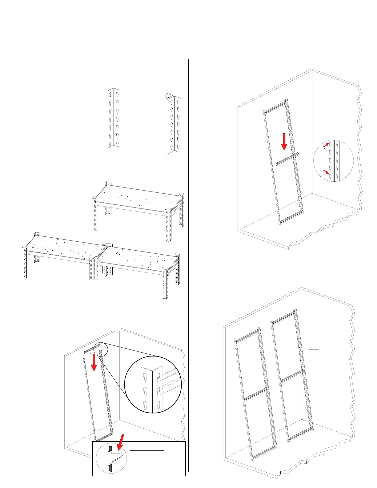
2. Depending upon whether
Angle Post
(EUR)
you are assembling a
single unit or an adder
unit, you may have one
or both of the styles of
upright shown at right:
"T" Post
(ZTP)
A single unit will use EUR angle posts for all four
uprights, as shown below in Figure A. If you plan
on assembling multiple sections, however, you
should build the starter unit with two ZTP
"T" posts on one end
(which will provide
common posts for
adjacent sections),
as shown in Figure B.
EUR
B. Two or more units with Angle Posts (EUR) on
each end and "T" Posts (ZTP) connecting each unit.
A. Single unit with
four Angle Posts (EUR).
ZTP
3. With help from an associate, or using a wall for
support, connect two EUR uprights (Ref. No. 1a)
together with two front-to-back end supports (Ref.
No. 2), one at the top and one
at the bottom. When
inserting supports,
be sure the
rivets are
fully seated
in the keyhole slots,
as shown.
NOTE: The
uprights
must be
positioned
so that the
narrow part
of the slots
is toward the floor,
as shown in the inset.
NOTE: Inset is shown
from opposite side.
IMPORTANT: The
support MUST be
inserted so that the flat
surface is on top as
shown in profile at left!
EUR
4. Place a third front-to-back end support in the
middle slots of the two uprights.
This forms one end of the
shelving unit.
NOTE: There
will be only
three (3)
front-toback end
supports
NOTE: Every
fourth keyhole
slot is shaped
differently (with a
flattened top) for
easier alignment
of supports (see
below).
per unit
end, as
shown.
These are
used for
rigidity
and are
not needed
at every
shelf level.
5. Repeat steps 3 and
4 to construct a second set of unit ends.
NOTE: If you are planning to install an adder
unit, this second end should consist of ZTP
Uprights (Ref. No. 1b) to act as an intermediate
assembly. Carefully
re-read through
step 2 to better
understand
this.
NOTE: If
assembling a
ZTP upright
assembly (for an
adder unit), place
the front-to-back
shelf supports on
both sides of the
"T" post, for a
total of six VDRS
front-to-back
supports instead
of three.
is flattened at top
Every 4th hole
 Loading...