

Tennsco Z-Line Heavy Duty Boltless Rack User Manual
ASSEMBLY INSTRUCTIONS & PARTS MANUAL #1940912
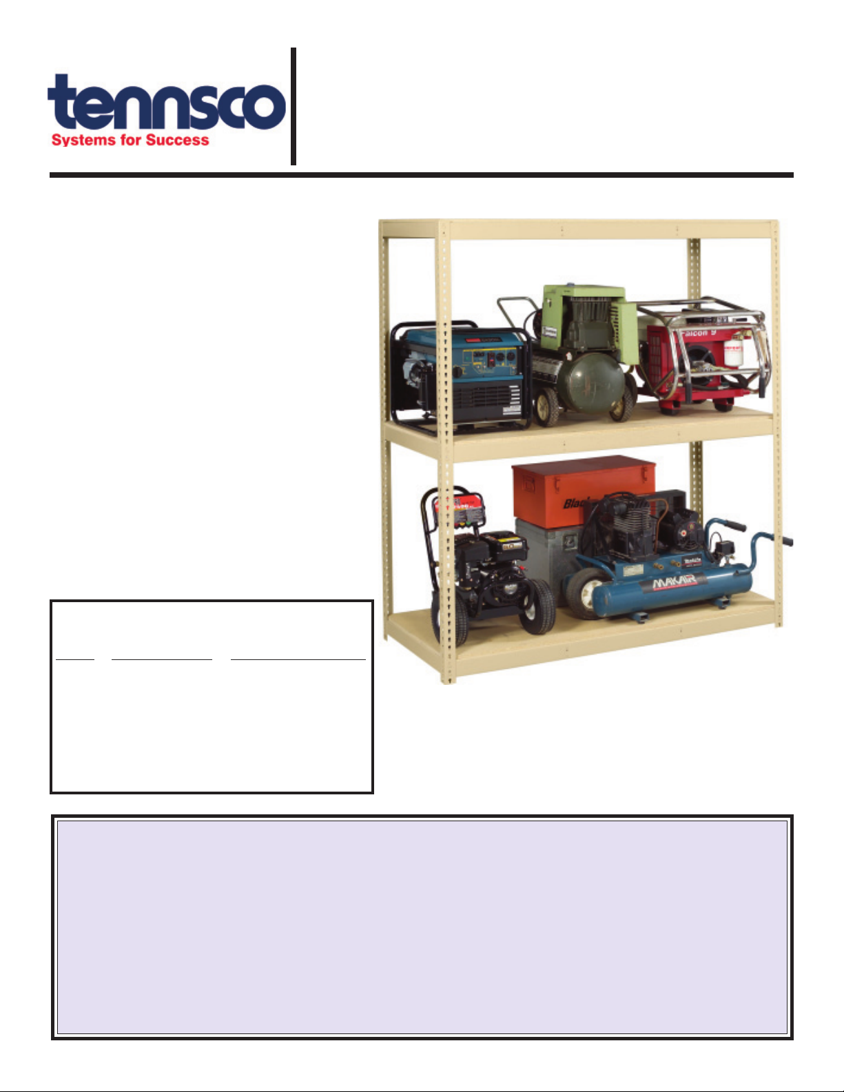
Z-Line Heavy Duty Boltless Rack
Installation Instructions
Tennsco Corp., Dickson, TN 37056-1888 • (615) 446-8000
RETAIN INSTRUCTIONS FOR FUTURE REFERENCE!
Congratulations on your purchase of ZLine Heavy Duty Boltless Rack from
Tennsco! Z-Line's interlocking keyhole
design not only makes installation fast
and easy but eliminates the need for
clips, gussets, sway braces or other
hardware commonly used in conventional
shelving. This allows completely free
access to your stored materials from all
sides of the unit.
Z-Line Boltless Rack is available in both
standard- and heavy-duty strengths, in a
variety of heights, widths and depths, to
fit virtually any storage application.
Adding an extra shelf is quick and easy.
And starter and adder units allow for
joining shelving units together.
SHELF LOAD CAPACITIES*
Unit Recommended Load Capacity,
Width Deck Supports With Deck Supports
48" 1 2500 lbs.
60" 1 2250 lbs.
72" 2 2000 lbs.
84" 3 1750 lbs.
96" 3 1600 lbs.
* Total weight capacity not to exceed 13,000 lbs. per unit (3,250 per post)
for SUR posts. Total weight capacity not to exceed 11,000 lbs. per unit
(5,500 lbs. per post) for ZTP posts.
LIMITED WARRANTY
Tennsco warrants goods purchased hereunder to be free of defects in materials and workmanship for a period of one (1) year from the date of shipment,
hereunder. This warranty shall not apply in the event goods are damaged as a result of misuse, abuse, neglect, accident, improper application, modification
or repair by persons not authorized by Seller, where goods are damaged during shipment, or where the date stamps on the goods have been defaced, modified
or removed. UNLESS CONSIDERED UNENFORCEABLE OR UNLAWFUL UNDER APPLICABLE LAW:
a. ALL IMPLIED WARRANTIES, INCLUDING BUT NOT LIMITED TO WARRANTIES OR MERCHANTABILITY AND FITNESS FOR A PARTICULAR
PURPOSE ARE HEREBY EXCLUDED:
b. BUYERS REMEDY, IF ANY, FOR ANY DEFECTIVE GOODS SHALL BE LIMITED TO A REFUND BY SELLER OR REPLACEMENT OF THE GOODS
AT SELLER’S OPTION, AND SHALL IN NO EVENT INCLUDE DAMAGES OF ANY KIND, WHETHER INCIDENTAL, CONSEQUENTIAL OR OTHERWISE.
NO GOODS ACCEPTED FOR RETURN WITHOUT PRIOR APPROVAL. Seller shall have the right to inspect any goods claimed to be defective at Buyers place
of business or require Buyer to return the goods to Seller for inspection on Seller’s premises. Transportation charges covering returned goods will be borne
by Seller only if such goods are proven to be defective, are covered by this warranty and are returned within the warranty period stated above.
Some parts may have sharp edges. CARE must be
taken when handling the pieces to avoid injury. For
safety, wear a pair of work gloves when assembling or
performing any maintenance on shelving.
GENERAL SAFETY INFORMATION
TENNSCO CORP., P.O. BOX 1888, DICKSON, TN 37056-1888
(615) 446-8000 (800) 251-8184
PK-1940912
ASSEMBLY OF HEAVY-DUTY BOLTLESS RACK
Tools Needed: A rubber mallet for seating the shelf supports. Two people are recommended for assembly.
Approximate assembly time: 15 to 30 minutes per section.
1. The reference numbers used throughout this sheet
refer to the illustration on the back cover. This is to
help you to identify the various
parts as they are mentioned.
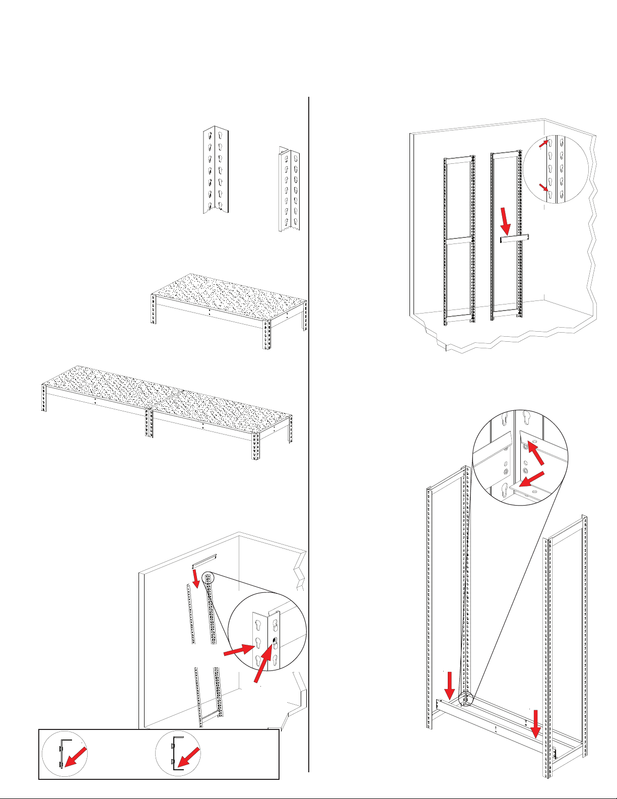
High Capacity
Post (SUR)
2. Depending upon whether you
are assmebling a single unit or
an adder unit, you may have
one or both of the styles of
upright shown at right:
A single unit uses SUR posts for all four uprights,
as shown below in Figure A. If you plan on
assembling mulpitle sections, however, you should
build your starter unit
with two ZTP posts
on one end, which
will provide common
posts for adjacent
sections, as shown
in Figure B.
SUR
A. Single unit with four
High Capacity Posts (SUR).
"T" Post
(ZTP)
4. Place a third front-to-back end support in the
middle keyholes of the two uprights
(or at whatever
level you want
your third shelf
to be). This
forms one
end of the
shelving unit.
5. Repeat steps
3 and 4 to
construct a
second set
of unit ends.
NOTE: If you
are planning to
install an adder unit,
this second set should consist of ZTP uprights
(Ref. No. 1b) to act as an intermediate assembly.
Carefully re-read through step 2 to better
understand this.
NOTE: Every
fourth keyhole
slot is shaped
differently (with
a flattened top)
for easier
alignment of
supports, as
shown above.
is flattened at top
Every 4th hole
ZTP
B. Two or more units with High Capacity Posts
(SUR) on each end and "T" Posts (ZTP) as
SUR
intermediate posts.
3.
With help from an associate, or using a wall for
support, connect two SUR uprights (Ref. No. 1a)
together with two front-to-back supports (Ref. No.
2), one at the top and one near the bottom (you
should leave the bottom keyhole
slot empty). Be sure the
supports are fully
NOTE: Inset is
shown from
opposite side.
seated in the slots,
as shown at right.
NOTE: Front-toback supports are
different than leftto-right supports.
Be sure you are
Narrow area
of keyhole slot
is at bottom
using the correct
supports on the
ends, as shown
in the box below.
FRONT-TO-BACK
SUPPORT (LRA)
has no flange at
the bottom.
LEFT-TO-RIGHT
SUPPORT (LRC) has
an added flange at the
bottom for strength.
Supports are
properly seated
when alignment
hole is fully visible
6. With the help of an
associate, connect
the two unit ends
with left-to-right
channel beams
(Ref. No. 3). If the
top flange on the
front-to-back end
support interferes
with the top flange
on the channel
beam, your
channel beam is
upside-down.
The flange with
the angled ends
must be on top,
as shown at right.
Be sure that the
channel beams
are fully seated,
as was illustrated
in step 3.
LRA
Proper orientation
of channel beam:
Flange with angled
end is on top;
Flange with flat
end is on bottom.
LRC
 Loading...