

Tennsco Q-Line Shelving User Manual
ASSEMBLY INSTRUCTIONS & PARTS MANUAL #2060699
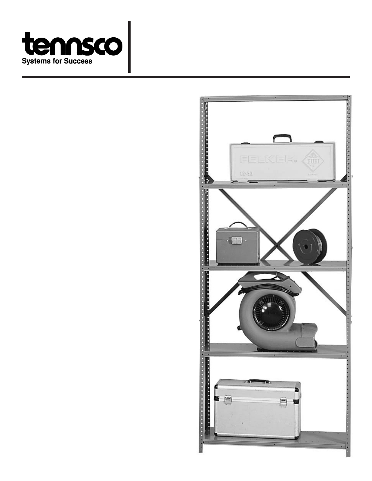
Q LINE INDUSTRIAL SHELVING, OPEN STYLE
Installation Instructions
Tennsco Corp., Dickson, TN 37056-1888 (615) 446-8000
RETAIN INSTRUCTIONS FOR FUTURE REFERENCE!
Congratulations on your purchase of
Q Line Industrial Shelving from Tennsco!
Q Line shelving is designed for storage
applications that demand strength and
versatility. Available in a variety of heights,
widths and depths, with either open or
closed ends and backs, Q Line shelving is
the answer for your heavy-duty storage
needs.
Q Line's unique box-formation shelving
structure provides added strength that
makes it the strongest shelf in its class.
The baked-on enamel finish assures years
of trouble-free service, even under the
most demanding situations. Compression
clips provide boltless shelf attachment,
making adding new shelves easy and
convenient. Shelves can be adjusted
quickly and easily in 1" increments,
providing versatility.
Units can be used stand-alone, bolted side
to side, or bolted back to back to suit
your needs.
A wide variety of accessory items are
available to suit your requirements,
whether your needs are within the office
or the factory.
GENERAL SAFETY INFORMATION
Some parts may have sharp edges. CARE
must be taken when handling various pieces to
avoid injury. For safety, wear a pair of work
gloves when assembling or performing any
maintenance on shelving.
PK-2060699
ASSEMBLY OF Q LINE INDUSTRIAL SHELVING
Tools Needed: A 7/16" nut driver or socket and a flathead screwdriver. Label holder requires a Phillips screwdriver.
Requires one or two people for assembly. Approximate assembly time: 2 people, 15 to 30 minutes per station.
1. The reference numbers used throughout this
sheet refer to the illustration on the back cover.
This is to help you to identify the various parts as
they are mentioned. NOTE: Number of shelves
per unit varies depending on unit purchased.
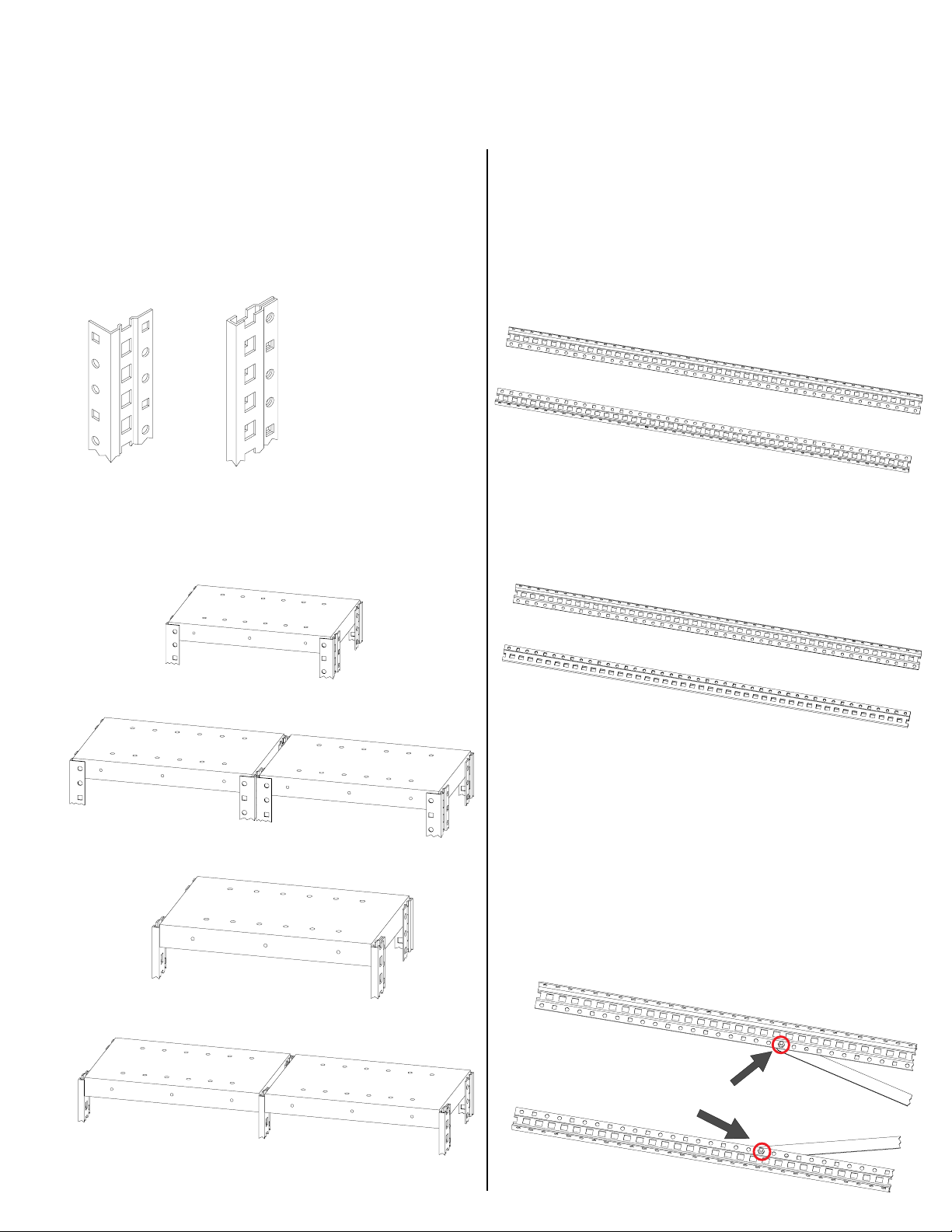
2. Q Line uprights come in three different styles, as
shown below:
Offset
Angle Post
(OAP)
These three upright styles may be used in
several different combinations. In order to better
understand these instructions, please examine the
following configurations to determine which type
of installation you will be assembling:
Standard
Beaded Post
(BTP)
3. Create the right side of the shelving units by
laying two uprights side by side on a flat
surface. Be sure that the short side of the
OAP upright(s) (Ref. No. 1a) is facing up, as
shown in Figure 3A.
IMPORTANT: One side of the upright is longer
than the other, and contains two sets of holes.
When laying the uprights side by side, this
long side should be flat on the floor, and the
short side should be pointing into
the air.
3a
(If your unit will use BTP or HBP uprights in
the front (Ref. Nos. 1b or 1c), be sure to
select the proper upright and that the open
edge is facing the OAP upright, as shown
below in Figure 3B.)
A. Single unit with
four Offset Angle Posts
B. Two or more units with four
Offset Angle Posts each
C. Single unit with two
Offset Angle Posts in rear and
two Standard or Heavy Beaded Posts in front.
OAP in back;
3b
BTP in front
4. Attach the two side sway braces (Ref. Nos.
2a or 2b), beginning in the 20th hole from the
top of each upright (approximately 20" from
the top), using two
(Ref. No. 6). The side sway braces attach
to the longer side of the uprights (the
side with two sets of holes). Bolt the braces
into the small holes near the edge of the
uprights as shown in circles at below. Note
the hole pattern of two round holes and then
one square hole, repeating every 3", which
should help facilitate proper placement of the
1
/4-20 x 5/8 bolts and nuts
bolts. Finger tighten only
at this point.
D. Two or more units using Standard or
Heavy Beaded Posts in front.
5. Attach the other end of both sway braces. The
information below will help you to know how
many holes should be between the top and
bottom of the sway braces. Count the holes
carefully, as an incorrect count will cause the
upright to be the wrong depth to hold the
shelves.
EXAMPLE:
12" deep unit has 34 holes
between bolts
Unit Depth Brace Length Distance Between Bolts
12" 36
15" 36
18" 36
24" 36
30" 43
36" 43
7
/8" 36 holes (35")
7
/8" 35 holes (34")
7
/8" 34 holes (33")
7
/8" 30 holes (29")
5
/8" 34 holes (33")
5
/8" 28 holes (27")
8. Have an associate hold one upright while you
place four shelf clips (Ref. No. 3) in the top
and bottom holes of each post, as shown
below.
6. Place one
1
/4-20 x 5/8 bolt and nut in the hole
where the two sway braces cross. Insert the
bolt from the outside of the uprights, so that the
nut will be inside the unit. Again, finger tighten
only for the time being.
7. Repeat steps 3 through 6 for the left uprights.
Again, be sure to note the type of uprights you
should be using (according to the illustrations in
step 2) for your type of installation. If you have
purchased an adder unit such as the example
in Figure 2D, please note that only ONE BTP or
HBP is used in between the units.
You should now have complete left and right
sides of your shelving unit, with sway brace
bolts and nuts still finger-tightened only.
9. Place a shelf (Ref. No. 4a or
4b) onto the bottom two clips.
 Loading...