

Be Sure To Save This Instruction Sheet For Future Reference!
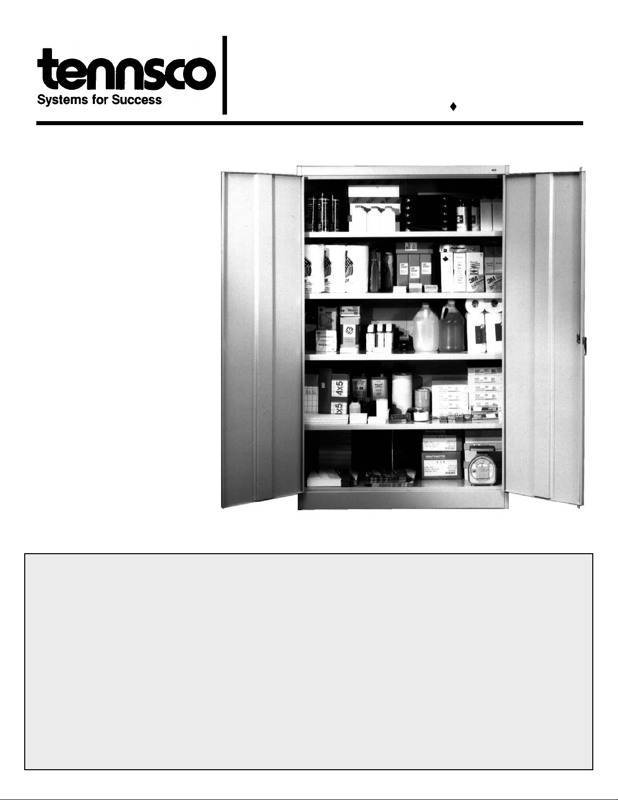
Congratulations on your
purchase of a Jumbo storage
cabinet from Tennsco! The
Model J-2478A Jumbo Cabinet
is 48"w x 24"d x 78" tall,
providing abundant storage
space. Our cabinets are rigidly
constructed to give you years
of dependable and efficient
service. Nylon lock-bar guides
ensure smooth, quiet
operation. A locking handle
with two keys provides a threepoint locking system for added
security. Sturdy adjustable
shelves provide exceptional
strength — up to 400 lbs per
shelf, evenly distributed. And
our baked-on powder finish
adds even more durability.
ASSEMBLY INSTRUCTIONS & PARTS MANUAL #1230402
JUMBO STORAGE CABINET
Model J2478A (consists of J478 & J2 4S)
Tennsco Corp., Dickson, TN 37056-1888 (615) 446-8000
GENERAL SAFETY INFORMATION: Some parts may have sharp edges. Care must be taken when handling various pieces to
avoid injury. Wear work gloves when assembling or performing maintenance on cabinet.
LIMITED WARRANTY
Tennsco warrants goods purchased hereunder to be free of defects in materials and workmanship for a period of one (1) year from the date of purchase,
hereunder. This warranty shall not apply in the event goods are damaged as a result of misuse, abuse, neglect, accident, improper application,
modification or repair by persons not authorized by Seller, where goods are damaged during shipment, or where the date stamps on the goods have
been defaced, modified or removed. UNLESS CONSIDERED UNENFORCEABLE OR UNLAWFUL UNDER APPLICABLE LAW:
ALL IMPLIED WARRANTIES, INCLUDING BUT NOT LIMITED TO WARRA NTIES OF ME RCHANTAB ILITY AND F ITNESS FOR A PARTICULAR PURP OSE ARE
a.
HEREBY EXCLUDED.
BUYERS REMEDY, IF ANY, FOR DEFECTIVE GOODS SHALL BE LIMITED TO A REFUND BY SELLER OR REPLACEMENT OF THE GOODS AT SELLER’S
b.
OPTION, AND SHALL IN NO EVENT INCLUDE DAMAGES OF ANY KIND, WHETHER INCIDENTAL, CONSEQUENTIAL OR OTHERWISE.
NO GOODS ACCEPTED FOR RETURN WITHOUT PRIOR APPROVAL. Seller shall have the right to inspect any goods claimed to be defective at
Buyers place of business or require Buyer to return the goods to Seller for inspection on Seller’s premises. Transportation charges covering returned
goods will be borne by Seller only if such goods are proven to be defective, are covered by this warranty and are returned within the warranty period
stated above.
Mailing Address:
TENNSCO CORP.
P.O. Box 1888 201 Tennsco Drive
Dickson, TN 37056-1888 Dickson, TN 37055
(615) 446-8000 (866) 446-8686 (toll free) (615) 446-8000 (866) 446-8686 (toll free)
www.tennsco.com www.tennsco.com
Shipping Address:
TENNSCO CORP.
PK-1230402
Step By Step Cabinet Assembly Instructions
(APPROXIMATE ASSEMBLY TIME: 2 people, 25 to 45 minutes)
TOOLS REQUIRED: A free 11/32" nutdr iver is included with each Tennsco cabinet. You will also need a flathead screwdriver and a hammer.
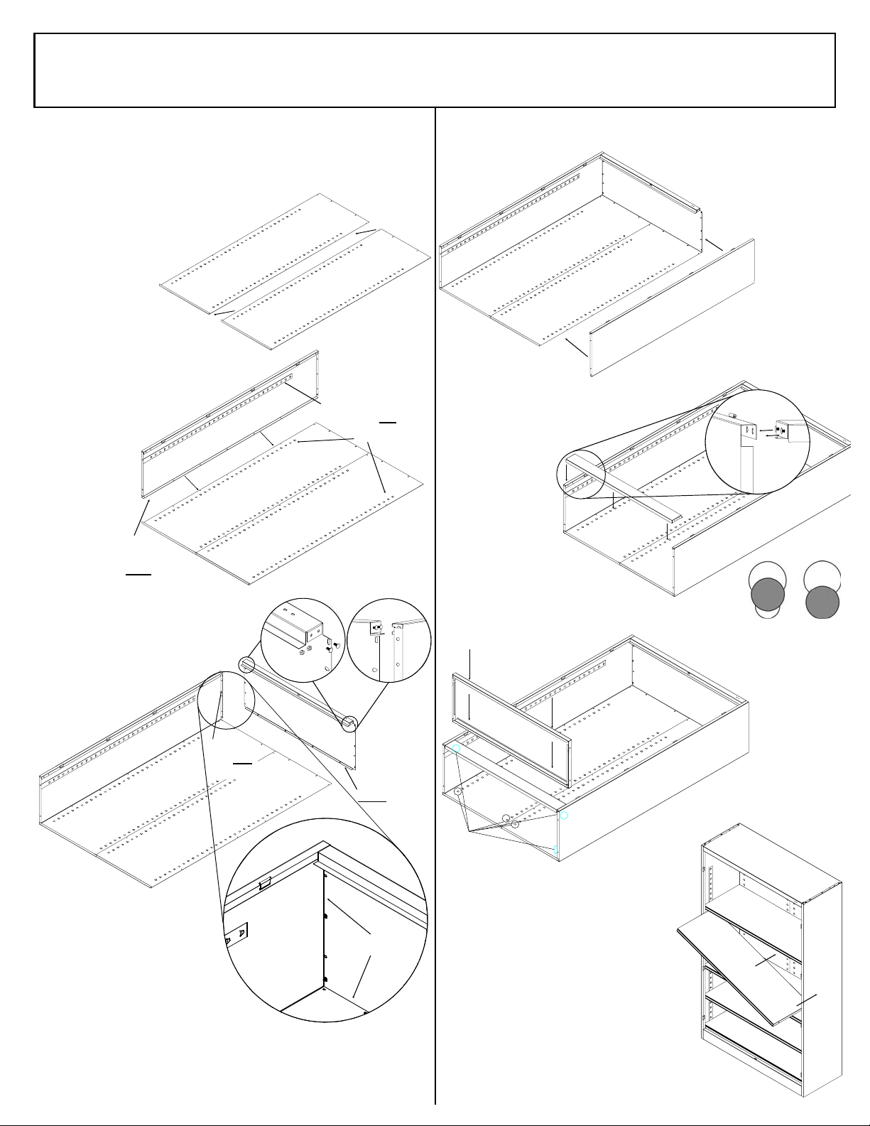
1. Before beginning assembly, comp are t he part s you have
received against the parts list on the back cover to ensure that
you have all the necessary pieces.
Place back panels on a sm oo th surf ac e,
2.
making sure that th e fl an ge s of both
panels are facing up. Overlap
the right panel over the left
panel. After aligning
Right
side overlaps
the left
the holes, bolt th e
two panels tightly
together with seve n bolts
and nuts.
3. Attach the left side to the back by
placing flange (A) aroun d th e
back and bolting tightly
together with seve n
B
All lances point UP on
both back
B
bolts and nuts.
Be sure that
all shelf
adjustment
strips (B) point
in the same
direction.
4. Insert bolts int o th e ou ts id e holes on
A
Flange goes
under back.
Inset A
the header por tion of the top (two on
each end as shown in Ins et A).
Attach the nuts, but do not tight en;
the bolt heads will later be
Insert bolts
in holes
inserted into th e ke yh ol e
slots of the sides,
as shown in
Inset B.
This flange
goes
over
the top.
This flange goes
under the back.
and side.
Inset B
6. Attach right side to back in the same manne r as yo u di d in ste p 3,
making sure that the side flange is
around the back and the top
flange is over the top. As
before, be sure that all
shelf adjustment strips
point in the
same direct-
ion. Attach
three bolts and
nuts acros s the top,
and seven bolts and nuts
down the side panel.
7. Insert bolts int o th e ou ts id e holes on the sill
(two on each end). Attach the nu ts, but
do not tighten. Plac e th e si ll
between the si de s at
the front of the
cabinet, inserting the loose bolt
Bolt heads
insert into
keyhole
slots.
heads into the
two keyhole sl ots
on each side. Make
sure the bolt heads are
Properly
Inserted
fully pulled down into the
bottom of the keyhole slots, as
shown at right. Secu rel y tighten the four
bolt heads.
Improperly
Inserted
8. Place a shelf into the
bottom lances, located
on the back and
sides of the unit.
The flange on
the sill will be
just in front of
the shelf.
5. Attach the
top to the back and left side by
inserting the bolt heads (whic h
you installed in step 4) into the
large end of the key hole s lots ,
No flanges visible
from the inside.
then sliding th em securely into
the smaller end. Be sure that the
back flange on the to p overlaps on the
outside of the back, while the flange on the
side panel fits ove r the left ed ge of the ca binet to p as illus trated ab ove.
Attach four bolts and nuts through the holes in the back, and three
bolts and nuts down each side. Tighten all bolts and nuts securely,
including the four bolt heads which you loosely attached in step 4.
Insert shelf into
the bottom notches
on back AND sides.
9. Using two people, set unit upright
and insert the remaining shelves
at the desired levels. Be sure that
the edge with no slots is toward
the cabinet fro nt. The slots on the
other three sides will fit over the
lances on the cabinet walls,
which will hold the shelf in place.
It is helpful to h ave two people
present to insert the shelves to
be sure that all lances are
engaged.

10. Attach the left door to th e
on
unit by placing th e do or
on the hinges, aligning the
holes, and driving four
hinge pins into plac e. If the
head of your hammer is too wide
to hit the pins without scrapi ng
the cabinet, it may be helpful to
place the flat edge of a
screwdriver on the pins and tap
the screwdriver with th e ha mm er.
11. Attach the right door in the same
manner as the left door,
placing the door on t he
hinges and connecting
by driving the remaini ng
four hinge pins
through the holes.
Handle/Locking System Installation Instructi
1. Place locking handle on right
hand door and fasten with
two slotted bolts with
lockwashers.
2. Turn handle to open
position and pl ac e
locking cam over
square shank of doo r
handle with latch
facing downward.
B
3. With handle still in open position, hook
locking bars to locking cam (A). Then, hold
lock bars in positi on wh il e sl id in g ny lon lock
bar guide inserts over lock bar ends and
through door slots (B).
12. Adjust the levele rs
underneath the front of
the unit to ensure th at
the cabinet is level . If the
cabinet is not level, the
doors will not align
properly.
13. Your cabinet assembly
is now complete except
for handle and locking
mechanism inst allation.
See next column for
handle and lock-bar
attachment.
A
B
5. Attach dummy
handle to left
door using the
two included
screws.
4. Place locking cam
retainer over square
shank of right door
handle and tap on
edges with hamm er
until retainer sits
firmly against the
locking cam.

PARTS LIST
Back Panel (2 Pieces) Top with Header (1 Piece)
(Part No.056TO)
Shelf (5 Pieces)
(Part No. 055BA)
Sill (1 Piece)
(Part No. 307)
Locking Handle w/Keys
& Hardware (1 Set)
Left Side Panel (1 Piece)
(Part No. 056LS)
Left Door (1 Piece)
(Part No. 056LD)
Dummy Handle
with Hardware (1 Set)
Right Side Panel (1 Piece)
(Part No. 056RS)
Right Door (1 Piece)
(Part No. 056RD)
Lock Bars (2 Pieces)
(Part No. 055SI)
Lock Bar Guide Insert
(2 Pieces—Nylon)
(Part No. 944GI)
Hinge Pin (8 Pieces)
(Part No. 944HP)
Tennsco makes every effort to ensure that all units ship complete with all parts and arrive undamaged. However,
should your unit contain missing or damaged parts, replacements may be obtained directly from Tennsco. To obtain
proper replacement parts, follow the instructions below, or fill out the form at: www.tennsco.com/partsorder.html
TO OBTAIN PROPER REPLACEMENT PARTS, PLEASE PROVIDE THE FOLLOWING INFORMATION:
• Model Number (J2478A) • Color • Your company name
• Purchase Date • Who product was purchased from • Contact person’s name
• Description of part(s) needed and part number(s) as shown in Parts List (above)
Tennsco Corp., P .O. Box 1888, Dickson , TN 37056-1888 Voice: (866) 446-8686 (toll free) Fax: (800) 722-013 4
If requesting parts by tel ep hone, ask for customer serv ic e and have as much of the abov e information ready as pos si ble.
(Part No. 944LH)
Locking Cam (1 Piece)
(Part No. 944LC)
3
⁄
Bolts #8-32 x
Nuts #8-32 (39 Pieces)
(Available Locally)
“ (39 Pieces)
8
(Part No. 043DH)
Cam Retainer (1 Piece)
(Part No. 944CR)
Wrench/Screwdriver Tool
(Part No. TOOL-2)
(Part No. 043LB)
 Loading...