

Tennsco Industrial Workbench User Manual
ASSEMBLY INSTRUCTIONS & PARTS MANUAL #1290605
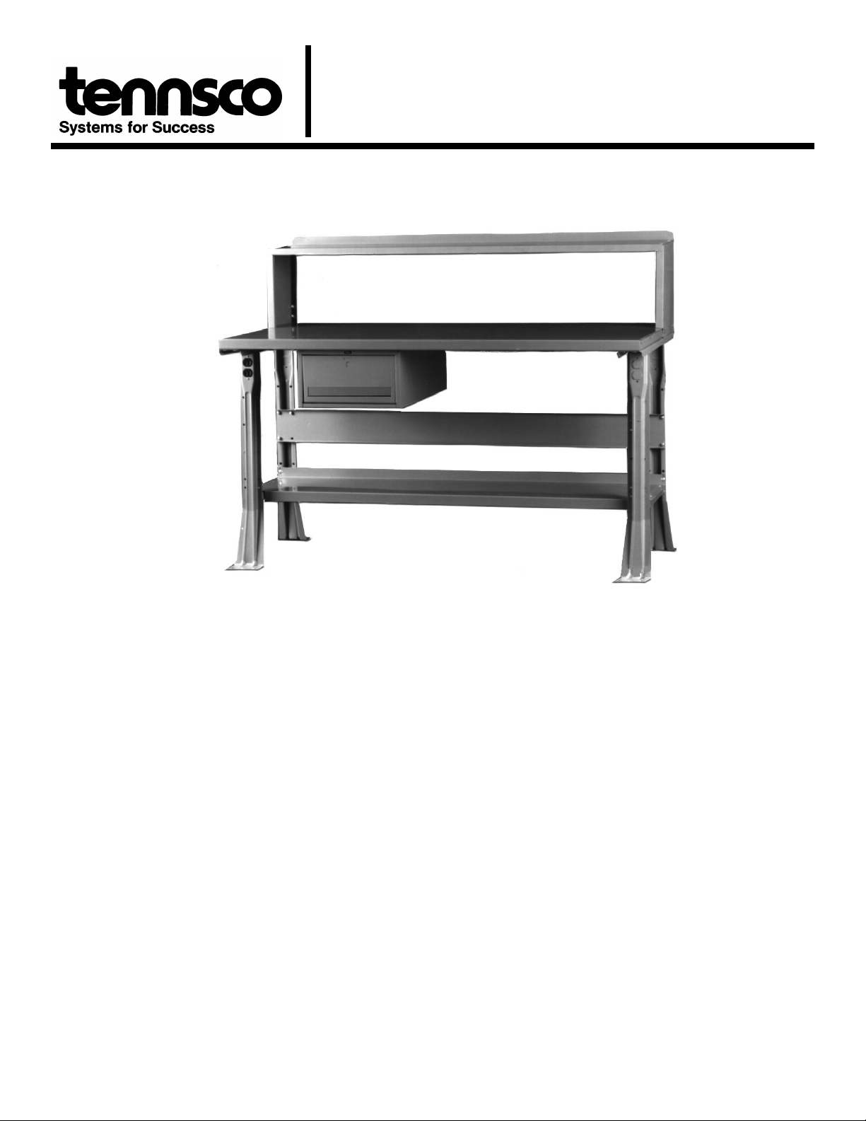
INDUSTRIAL WORKBENCH
Tennsco Corp., Dickson, TN 37056-1888 * (615) 446-8000
READ INSTRUCTIONS CAREFULLY BEFORE ATTEMPTING
TO ASSEMBLE YOUR Tennsco INDUSTRIAL WORKBENCH.
RETAIN INSTRUCTIONS FOR FUTURE REFERENCE!
DESCRIPTION
Rugged construction makes these
ideally suited for factories, shops, garages, labs, etc.
Workbenches are shipped unassembled with tops and legs
in separate cartons.
The fixed height, flared legs have all-welded steel
construction with punched holes for attaching stringer, and
lower shelf flanged feet have holes for securing to floor. Legs
are 32" high and 30" or 36" deep.
Duplex knock-outs are punched in each leg to receive a steel
city electrical box, model #CDOW (2.5" X 2" X 3").
Tennsco
tops are available in a choice of two widths and
two depths and are pre-drilled for mounting to various
workbench bases. A steel stringer is included to provide
extra rigidity.
Steel Benchtops
(S) are constructed of smooth steel
surfaces, reinforced with channels at each end. There are
no exposed sharp edges or corners.
Hard Maple Laminate Benchtops
laminated solid hard maple with a smooth oil-seal na tural finish.
Plastic Laminate Benchtops
linen, maintenance-free, high pressure non-conductive
plastic laminate over a compressed wood core with a
phenolic backer sheet.
Compressed Wood Benchtops
constructed of tempered hardboard top and bottom surfaces
laminated to a high density compressed wood core. A
smooth, sealed finish gives a durable, non-porous surface.
Available options
are listed in the replacement parts list
included in these instructions.
Tennsco
(W) are 1
(P) are 1
(C) are 1
workbenches
3
⁄
" thick
4
5
⁄
" thick with grey
8
3
⁄
" thick and
4
SPECIFICATIONS
Overall Dimensions
All 3060 models ..........................60"w x 30"d x 33
All 3072 models ..........................72"d x 30"w x 33
All 3660 models ..........................60"d x 36"w x 33
All 3672 models ..........................72"d x 36"w x 33
Basic Construction
Steel Top
Top.................................................12 gauge steel
Reinforcing Channels..................... 14 gauge steel
Hard Maple Laminate Top
Top..............................................Laminated Maple
Compressed Wood Top
Top........Hardboard with Compressed Wood Core
Plastic Laminate Top
Top..............Laminated High Pressure Plastic with
Compressed Wood Core
Legs...................................................... 14 gauge steel
Upper and lower leg crossmembers..... 13 gauge steel
Stringer ................................................. 14 gauge steel
Options Available:
Side and back rails Lower Shelf
Standard and electronic riser Stackable Drawer
1
⁄
"h
2
1
⁄
"h
2
1
⁄
"h
2
1
⁄
"h
2
GENERAL SAFETY INFORMATION
Some parts may have sharp edges. CARE must be taken
when handling various pieces to avoid injury. For safety,
wear a pair of work gloves when assembling or performing
any maintenance on workbench.

Step By Step Installation Instructions
(Proceed to next step on optional items not purchase)
Tools required: Slotted screwdriver, Phillips screwdriver, and 7/16" & 3/8" wrenches or nut drivers (use 2 people for assembly)
1. Place legs (1) in upright position as shown in Figure 1.
Legs should be placed approximately 53" apart for 60"
units and 65" apart for 72" units.
2. Attach stringer (3) [provided with top] to bench legs
using center four holes in back legs. Fasten with eight
bolts, nuts, and washers.
3. Attach bench top (4) to frame assembly using the
applicable instructions.
Solid Maple Top; Compressed Wood on
Wood Top;
Plastic Lam inate Top
or
(Figure 2):
3a. Place bench top on a smooth, non-marring
surface with top side facing down.
3
⁄
3b. Using sixteen #14 x
" hex head slotted
4
screws, attach legs to the under side of
bench top through pre-drilled holes.
Steel Top
(Figure 3):
3a. Place bench top on a smooth, non-marring
surface with top side facing down.
3b. Insert top end channel (5) in each end of
bench top and align bench top, leg, &
channel holes. (There are two extra top end
channels provided, for a total of four, for
installing an optional pedestal or drawer).
Secure with four
1
⁄
"-20 x
4
5
⁄
" bolts. Four
8
weld nuts are provided on each channel.
3c. Secure leg to top using
1
⁄
" -20 x
4
5
⁄
8
" bolts
inserted in second hole from each corner.
(Note: holes run along front facing [2 holes]
and back facing [2 holes].)
OPTIONAL
4.
Wood Tops:
Stackable Drawer Attachment (Figure 4):
(mounting brackets not used):
4a. Remove drawer (6) from housing (7).
4b.Secure lock hasp (8) onto two bolts
extending down from top of housing using
1
⁄
two
"-20 nuts.
4
4c. Position housing (7) under bench top in
desired location and drill holes as required
1
(recommendation:
⁄
" offset from front of
2
bench top). (Note: mounting brackets are
not used when installing on wood top.)
4d. Secure the housing to the bench top using
3
four #14-
⁄
" hex head slotted wood
4
screws.
4e.Once bench assembly is in an upright
position (see step 5), insert drawer into
housing.
Steel Top:
4a. Remove drawer (6) from housing (7).
4b.Secure lock hasp (8) onto two bolts
extending down from top of housing using
1
⁄
two
"-20 nuts.
4
4c. Secure one mounting bracket (5) to left
1
⁄
side of housing with two
"-20 bolts and
4
nuts. On 30" deep top, the bracket should
1
extend 10
top, it should extend 16
⁄
" behind housing; on 36" deep
2
1
⁄
" behind the
2
housing.
4d. Attach a second mounting bracket (5) to
welded nut
1
⁄
"-20 bolt. Do not tighten yet, as having
4
in rear of housing only
the bracket loosely attached simplifies
mounting to the workbench top.
4e.To attach drawer assembly to the
workbench top, insert back end of the left
drawer bracket diagonally into flange on
the rear underside of the top. Then, slide
the front of the bracket into the front flange
until the drawer assembly is aligned evenly
with the front of the workbench top.
4f. Insert the back end of the loosely attached
right drawer bracket into the flange on the
rear underside of the workbench top. Then,
slide the front of the bracket into the front
flange until bracket is aligned evenly with
front of workbench top.
4g. Align holes in mounting brackets and top in
desired location and secure using four
1
⁄
"-20 bolts and nuts.
4
4h.Attach front end of bracket to front of
1
⁄
housing using one
"-20 bolt and nut.
4
Secure the rear bolt and nut which was left
loose in step 4d.
4i. Once bench assembly is in upright position
(see step 5), insert drawer in housing.
Drawer To Drawer Assembly:
4a. Remove drawer from housing.
4b.Secure lock hasp (8) onto two bolts
extending down from top of housing using
1
⁄
two
"-20 nuts.
4
1
⁄
4c. Bolt housing together with 4
"-20 bolts
4
and nuts.
4d. Once bench assembly is in upright position
(see step 5), insert drawer in housing.
with one
 Loading...