

Tennsco EB-1-3072S-MGY, EB-2-3672C-MGY, EB-1-3672M-MGY, EB-2-3072S-MGY, EB-1-3072C-MGY User Manual
...
ASSEMBLY INSTRUCTIONS & PARTS MANUAL #1340397
ELECTRONIC WORKBENCH
Tennsco Corp., Dickson, TN 37056-1888 * (615) 446-8000
READ INSTRUCTIONS CAREFULLY BEFORE ATTEMPTING
TO ASSEMBLE YOUR Tennsco ELECTRONIC WORKBENCH.
RETAIN INSTRUCTIONS FOR FUTURE REFERENCE!
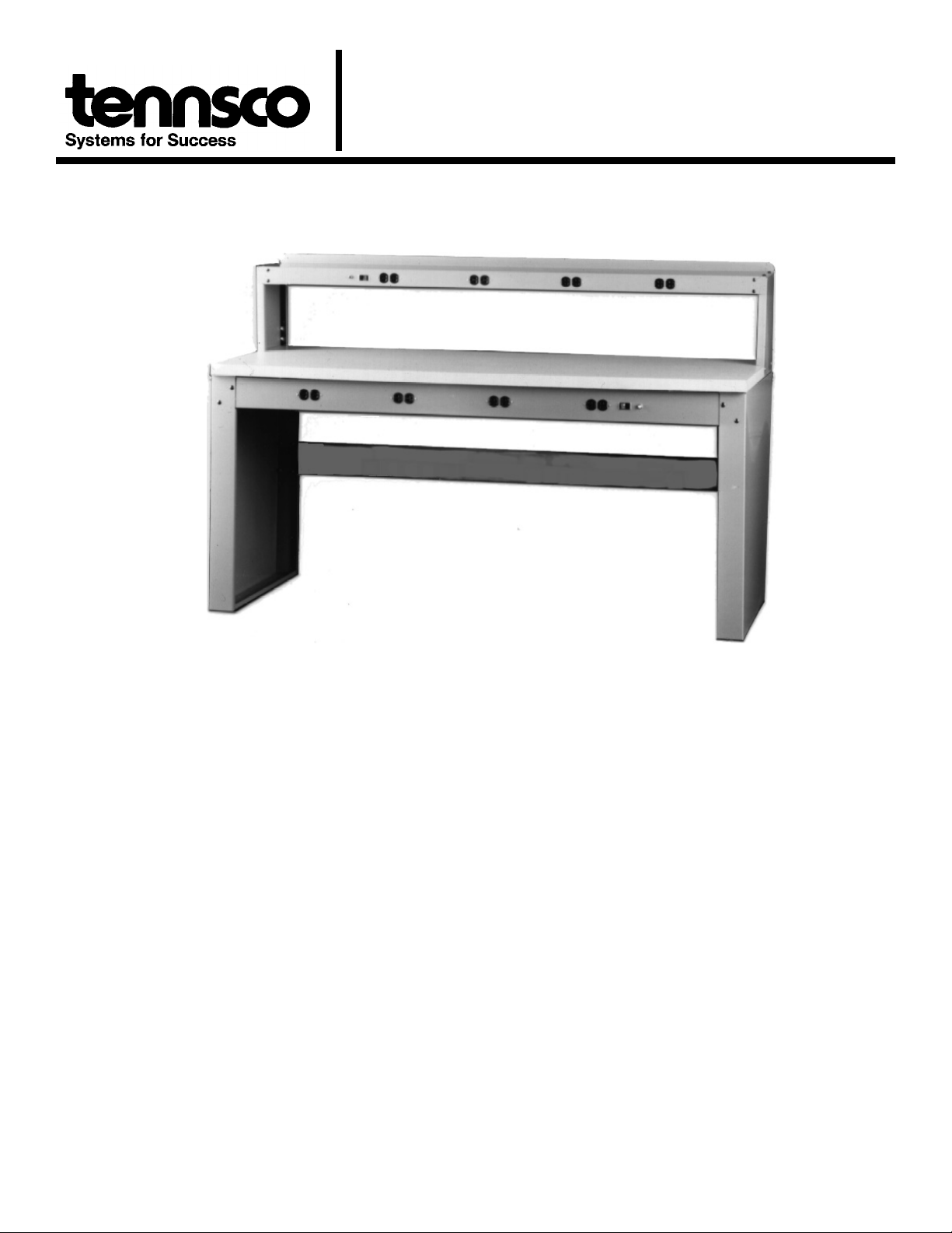
DESCRIPTION
Tennsco
electronic ass embly, tes ting, pr oduct de velopment an d
other u ses w here a ccess to multiple power outlets is
important. The workbench can use either 30" x 60", 30" x
72" wood tops or 36" x 72" steel tops (see below). Workbench
legs and frames are box formed for strength and r igidity.
Frame front panel has knockouts for four duplex receptacles
as well as a switch and circuit breakers (order optional wiring
kit separately). Removable cover behind r eceptacle panel
facilitates wiring and prevents contact with rear terminals.
Tennsco
two de pths a nd ar e pr e-drilled for mounting to var ious
workbench bases.
Steel Benchtops
surfaces, reinforced with channels at each end. There are
no exposed s harp edges or corners. A s teel s tringer is
included to provide extra rigidity.
Hard Maple Laminate Benchtops
laminated solid hard maple with a smooth oil-seal natural finish.
Plastic Laminate Benchtops
linen, m aintenance-free, h igh pr essure non- conductive
plastic l aminate o ver a com pressed w ood core w ith a
phenolic backer sheet.
Compressed Wood Benchtops
constructed of tempered hardboard top and bottom surfaces
laminated to a high density compr essed wood cor e. A
smooth, sealed finish gives a durable, non-porous surface.
Available options
included in these instructions.
e lectronic wo rkbenches a re des igned for
tops are available in a choice of two widths and
( S) ar e cons tructed of smo oth st eel
(W ) a re 1
5
⁄
(P) are 1
(C) ar e 1
ar e listed in the r eplacement par ts list
" thick with gr ey
8
3
⁄
" t hick
4
3
⁄
" thick and
4
SPECIFICATIONS
Overall Dimensions
All 3072 models .......................... 72"w x 30"d x 33
All 3672 models .......................... 72"w x 36"d x 33
Basic Construction
Steel Top
Top ..................................................12 gauge steel
Reinforcing Channels ......................14 gauge steel
Hard Maple Laminate Top
Top ..............................................Laminated Maple
Compressed Wood Top
Top ........ Hardboard with Compressed Wood Core
Plastic Laminate Top
Top ..............Laminated High Pressure Plastic with
Compressed Wood Core
Panel Legs.............................................16 gauge steel
Stringer ..................................................14 gauge steel
Wireway Cover ......................................20 gauge steel
Receptacle Panel...................................16 gauge steel
Back Panel.............................................16 gauge steel
Options Available:
Side and back rails Lower Shelf
Standard and electronic riser Stackable Drawer
1
⁄
"h
2
1
⁄
"h
2
GENERAL SAFETY INFORMATION
Some parts may hav e sharp edges. CA RE must be taken
when handling v arious pieces to avoid injury. F or safety,
wear a pair of work gloves when assembling or performing
any maintenance on workbench.

Step By Step Installation Instructions
(Proceed to next step on optional items not purchase)
Tools required: Slotted screwdriver, Phillips screwdriver, and 7/16" & 3/8" wrenches or nut drivers (use 2 people for assembly).
1. Place the panel legs (1) in an upright position as shown
in Figure 1 of the assembly drawings. The legs should
be plac ed appr oximately 53" apart for 60" units and
65" apart for 72" units.
2. Place r eceptacle p anel ( 2) i nside pa nel l egs an d
secure with four
1
⁄
4
"-20 x
5
⁄
" bolts and nuts. (Stringer
8
mounting holes go to the rear.)
3. Attach stringer (4) [provided with top] to back of panel
legs as shown. F asten with eight
1
⁄
4
"-20 x
5
⁄
" bolts,
8
nuts and washers.
4. Set back panel (3) inside panel legs and secure with
four
OPTIONAL
5.
1
⁄
4
"-20 x
5
⁄
" bolts and nuts.
8
Wiring Kit
5a. Install optional wir ing k it ( WK-1) into r eceptacle
panel using the ins tructions pr ovided with each
wiring kit.
DO NOT CONNECT POWER TO UNIT UNTIL
ENTIRE UNIT HAS BEEN ASSEMBLED.
6. Attach the wireway cover (5) to the back bottom flange
of the r eceptacle panel with four #10 sheet metal
screws.
7. Attach bench top ( 6) to fr ame ass embly using the
applicable instruction below:
Solid Maple Top; Compressed Wood on
Wood Top;
Plastic Lam inate Top
or
(Figure 2):
7a. Place bench top on a smooth, non-marring
surface with top side facing down.
7b. For 30" top, attach leg assembly to under
side of bench top thr ough pre- drilled holes .
3
⁄
Secure with #14 x
" wood screws: six in
4
each panel leg. Predilled holes on 36" top
will not line up with the holes on the leg
assembly.
NOTE: W hen installing a receptacle panel
(2) or back panel (3) on a wood top, use a
drill bit to drill
5/32"
pilot holes along the
front & b ack e dges of b enchtop.
Steel Top
(Figure 3):
7a. Place bench top on a smooth, non-marring
surface with top side facing down.
7b. Attach leg assembly to under side of bench
top thr ough punc hed holes . S ecure with
1
⁄
4
"-20 x
5
⁄
" bolts and nuts: one in second
8
hole fr om eac h cor ner of top; eight in
receptacle panel; and eight in back panel.
7c. Insert channel (7) in each end of bench top.
7d. Align bench top, panel legs , and channel
holes. Secure with four
1
⁄
4
"-20 x
5
⁄
" bolts.
8
Note fo ur w eld n uts ar e pr ovided on
channels.
8. Set bench assembly upright and recheck all nuts, bolts
and screws for tightness.
OPTIONAL
9.
Stackable Drawer Attachment (Figure 4):
9a. Remove drawer (15) from housing (16).
9b. Secure lock hasp (17) to housing top using the two
1
⁄
"-20 x
4
5
⁄
" bolts ex tended down fr om top of
8
housing.
9c. Secure long mounting brackets ( 14) to r ear of
housing, with br acket flanges tur ned downwar d,
1
⁄
using four
"-20 x
4
should ex tend 10
5
⁄
" bolts and nuts. B racket
8
1
⁄
" b ehind housing. ( NOTE:
2
When installing drawer onto a wood top, drawer is
secured dir ectly into the wood top; no mounting
brackets ar e us ed. H oles m ust be dr illed as
needed.)
9d.ENSURE TH AT WOR KBENCH POWER
SUPPLY IS NOT CONNE CTED B EFORE
PERFORMING NEXT STEP.
9e. Attach dr awer un it to wo rkbench by r emoving
wireway cov er fr om r eceptical ho using an d
aligning front slots in top of hous ing with holes in
receptacle panel (short mounting brackets are not
used). Secure with two
1
⁄
4
"-20 x
5
⁄
" bolts and nuts.
8
9f. Align holes in mounting brackets with holes in back
panel flange and secure with two
1
⁄
4
"-20 x
5
⁄
8
" bolts
and nuts.
9g. Replace wireway cover.
9h. Insert drawer in housing.

10.
OPTIONAL
OPTIONAL
11.
Riser Attachment
Standard Riser
(Figure 1):
10a. Secure riser shelf (9) to supports using two
bolts and nuts on each end.
10b. Secure riser supports (8) to top end, using
four bolts and nuts (or four #14 wood screws
for wood tops).
Electronic Riser
(Figure 5):
10a. Secure riser supports (8), to top end, using
four bolts and nuts (or four #14 wood screws
for wood tops).
10b. Install optional wiring kit into electronic riser
shelf (10) us ing ins tructions pr ovided with
each wiring kit.
DO NOT CONNECT POWER TO UNIT
UNTIL ENTIRE UNIT IS ASSEMBLED.
NOTE: If wi ring k it was not pur chased,
proceed to step 10c.
10c. Align holes in flanges of wireway trough (11)
with holes in riser shelf. Insert four #10 sheet
metal screws and tighten.
10d. Secure e lec tronic r iser s helf ( 10) t o
supports, using two bolts and nuts on each
end.
Riser to Riser:
10a. Secure riser supports to lower riser supports
with flange down, using four bolts and nuts.
10b. Secure r iser shelf to supports using two
bolts and nuts on each end.
Side and Back Rail Attachment
11a.
Bolt side rail (12) to the right side of top end
attachment with four bolts and nuts (for wood
tops, use #14 wood screws and drill holes as
needed). Be sure that the rounded corners of
side ra il are tow ard th e front of the
workbench.
11b. Repeat step 11a to install rail for left side.
11c. Place back rail (13) across back and around
the outside of the side rails. Secure to bench
top with fiv e bolts, nuts and washer s. ( For
wood tops use five #14 wood screws). Use
two bolts, nuts and washers at each end to
fasten to side rails.
LIMITED WARRANTY
Tennsco warrant s goods purchased hereunder to be f ree of
defects in materials and workmanship for a period of one (1) year
from t he date of shipment, hereunder. This warrant y shal l not
apply i n the event goods are dam aged as a result of misuse,
abuse, negl ect, acci dent, i mproper application, modification or
repair by persons not aut horized by S eller, where goods are
damaged duri ng shi pment, or where the date stamps on the
goods have been def aced, m odified or rem oved. UN LESS
CONSIDERED UNENFORCEABLE O R UNLAWF UL UNDER
APPLICABLE LAW:
a. ALL I MPLIED W ARRANTIES, INCLUDI NG BUT NO T
LIMITED TO WARRANTIES OR MERCHANT ABILITY AND
FITNESS FOR A PART ICULAR PURPOSE ARE HEREBY
EXCLUDED.
b.BUYERS REMEDY, IF ANY, FOR ANY DEFECTIVE GOODS
SHALL B E L IMITED T O A REF UND BY SELLER OR
REPLACEMENT OF THE G OODS AT SEL LER’S OPTION,
AND SHALL IN NO EVENT I NCLUDE DAMAG ES OF ANY
KIND, WHET HER I NCIDENTAL, CONSEQ UENTIAL OR
OTHERWISE.
NO GOOD S A CCEPTED FOR R ETURN WI THOUT P RIOR
APPROVAL. Sel ler shal l have the ri ght t o i nspect any goods
claimed to be defective at Buyers place of business or requi re
Buyer t o ret urn t he goods t o S eller f or i nspection on S eller’s
premises. Transport ation charges coveri ng returned goods wi ll
be borne by Seller only if such goods are proven to be defective,
are covered by this warranty and are returned within the warranty
period stated above.
TENNSCO CORPORATION
P.O. Box 1888
DICKSON, TN 37056-1888
(615) 446-8000 (800)
Hard Maple Laminate Benchtop Maintenance:
Clean when necessary with warm water, soap or detergent.
Wipe dry immediate ly. Sc ouring p owder, st eel w ool or
sandpaper can be used for stubborn stains and mars. Allow
a generous quantity of linseed oil or mineral oil to penetrate
all surfaces for five minutes before removing all excess oil.
Excessive dr yness or hum idity c an ca use c racks or
warping. Cracks should be filled w ith w ood filler, sa nded
smooth and re-oiled. Warping can be prevented by securely
attaching top to bench legs.
251-8184

REF. NO. DESCRIPTION PART NUMBER QTY.
1 Panel Legs (All Units) LP-3230 1 (PR.)
2 Receptical Panel (All Units) WOP-72 1
3 Back Panel (All Units) 2221ABP-72 1
4 Stringer (60" Wide) WBS-60 1
Stringer (72" Wide) WBS-72 1
5 Wireway Cover (All Units) 221AWC-72 1
6 Steel Bench Top w/Stringer (30" x 60") T-3060 1
Steel Bench Top w/Stringer (30" x 72") T-3072 1
Steel Bench Top w/Stringer (36" x 72") T-3672 1
Compressed Wood on Wood Top w/Stringer (30" x 60") CT-3060 1
Compressed Wood on Wood Top w/Stringer (30" x 72") CT-3072 1
Compressed Wood on Wood Top w/Stringer (36" x 72") CT-3672 1
Plastic Laminate Top w/Stringer (30" x 60") PT-3060 1
Plastic Laminate Top w/Stringer (30" x 72") PT-3072 1
Plastic Laminate Top w/Stringer (36" x 72") PT-3672 1
Solid Maple Top w/Stringer (30" x 60") MT-3060 1
Solid Maple Top w/Stringer (30" x 72") MT-3072 1
Solid Maple Top w/Stringer (36" x 72") MT-3672 1
7 Top End Channel (Included w/Top)
8 Riser Support (All Units) WBRS-2 2
9 Riser Shelf (60" Wide) WBRS-60 1
Riser Shelf (72" Wide) WBRS-72 1
10 Electronic Riser Shelf (60" Wide) EWRS-6015 1
Electronic Riser Shelf (72" Wide) EWRS-7215 1
11 Wire trough (60" Wide) EWWT-60 1
Wire trough (72" Wide) EWWT-72 1
12 Side Rail (30" Deep Units) 189SS 2
Side Rail (36" Deep Units) 404SS 2
13 Back Rail (60" Wide) 189BS1 1
Back Rail (72" Wide) 404BS 1
14 Long Mounting Bracket (WBD-2) 976LB 2
15 Drawer (WBD-2) 976CDW 1
16 Drawer Housing (WBD-2) 976CDH 1
17 Padlock Hasp (WBD-2) 976H 1
18 Tray (WBD-2) 976T 1
19 Divider (WBD-2) WBDD-12 1
❈
❈
•
•
•
•
•
❈
Wiring Kit (not shown in figure) WK-1 1
Cam Lock CL-1 1
1
⁄
4
1
⁄
4
1
⁄
4
#14 x
#10 x
5
"-20 x
⁄
" Bolt
8
"-20 Nut
" Lockwasher
3
⁄
" Hex Head Slotted Wood Screw
4
1
⁄
" Sheetmetal Screw
2
♦
♦
♦
♦
♦
Optional Accessory
49B134
Tennsco makes every effort to ensure that all units ship complete with all parts and arrive undamaged.
However, should your unit contain missing or damaged parts, please contact your purchase location.
 Loading...