

Tennsco Bulk Storage Shelving with Plywood Beams User Manual
ASSEMBLY INSTRUCTIONS & PARTS MANUAL #2080402
BULK STORAGE RACK W/PL YWOOD STYLE BEAMS
Installation Instructions
Tennsco Corp., Dickson, TN 37056-1888 • (615) 446-8000
RETAIN INSTRUCTIONS FOR FUTURE REFERENCE!
Congratulations on your purchase of a
Bulk Storage Rack from Tennsco! Bulk
Storage is ideal for storing heavy duty
items that can be hand-loaded (not for
use with fork lifts). Bulk Storage utilizes
Z-beam construction for maximum
strength. The beams are electrically
welded and made of 14-gauge heavyduty steel, giving a load capacity of
between 2150 and 4150 lbs. per shelf
(see chart below for load capacities and
recommended supports).
Installation is simple; shelving can be
expanded, reconfigured, or disassembled with ease, and no tools are
required. Shelf levels are adjustable in 2"
increments for maximum versatility.
GENERAL SAFETY
INFORMATION
Some parts may have sharp edges.
CARE must be taken when handling
various pieces to avoid injury. For
safety, wear a pair of work gloves
when assembling or performing any
maintenance on shelving.
NOTE: Tennsco's Bulk Storage Rack
is intended for HAND loading only;
no fork lifts.
SHELF LOAD CAPACITIES AND
RECOMMENDED SUPPORT ANGLES PER LEVEL
24" DEEP 36" DEEP 48" DEEP
Supports Load Supports Load Supports Load
Width Per Level Cap. Width Per Level Cap. Width per Level Cap.
48" 2 4150 lbs. 48" 2 3000 lbs. 48" 2 1500 lbs.
60" 2 3800 lbs. 48" 4 4150 lbs. 48" 4 2250 lbs.
72" 3 2750 lbs. 60" 2 3800 lbs. 48" 6 3000 lbs.
96" 4 2150 lbs. 72" 3 2750 lbs. 48" 8 4150 lbs.
96" 4 2150 lbs. 60" 2 1500 lbs.
60" 4 2250 lbs.
60" 6 3800 lbs.
72" 3 2750 lbs.
96" 4 2150 lbs.
PK-2080402
ASSEMBLY OF BULK STORAGE SHELVING
Tools Needed: None. Approximate assembly time: 2 people, 10 to 20 minutes per section.
1. The reference numbers used throughout this
sheet refer to the illustration on the back cover.
This is to help you to identify the various parts
as they are mentioned while assembling.
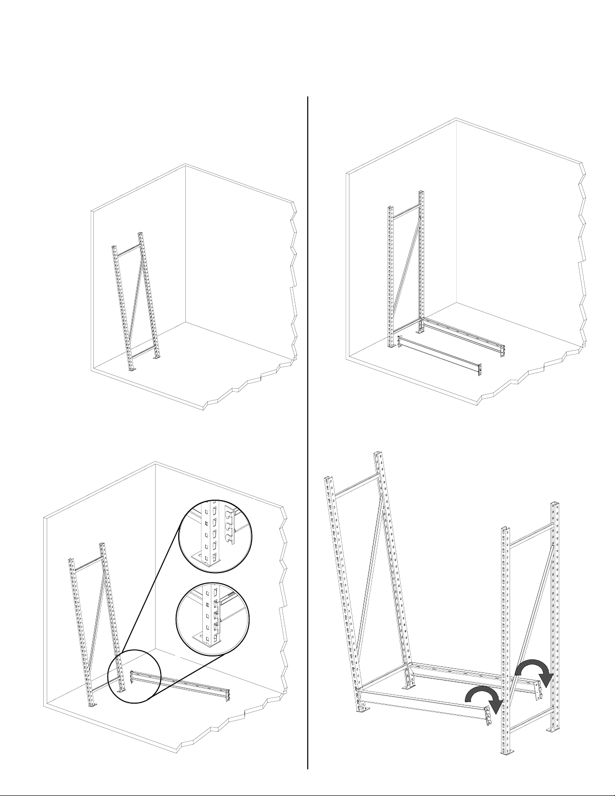
2. Lean one upright
(Ref. No. 1)
against the
wall, or
have an
associate
hold it
for you.
4. Attach the second bottom beam in the same
manner as you
did in step 3.
3. Attach one bottom beam (Ref. No. 2) to the
upright, hooking the tapered fingers into the
holes on the upright as shown in inset
drawings below.
5. Holding the second upright in place, lift the
loose ends of the two bottom beams and fit
them into place on the upright. The
unit should now have enough
stability to stand up unassisted for
the remainder of the assembly.
 Loading...