

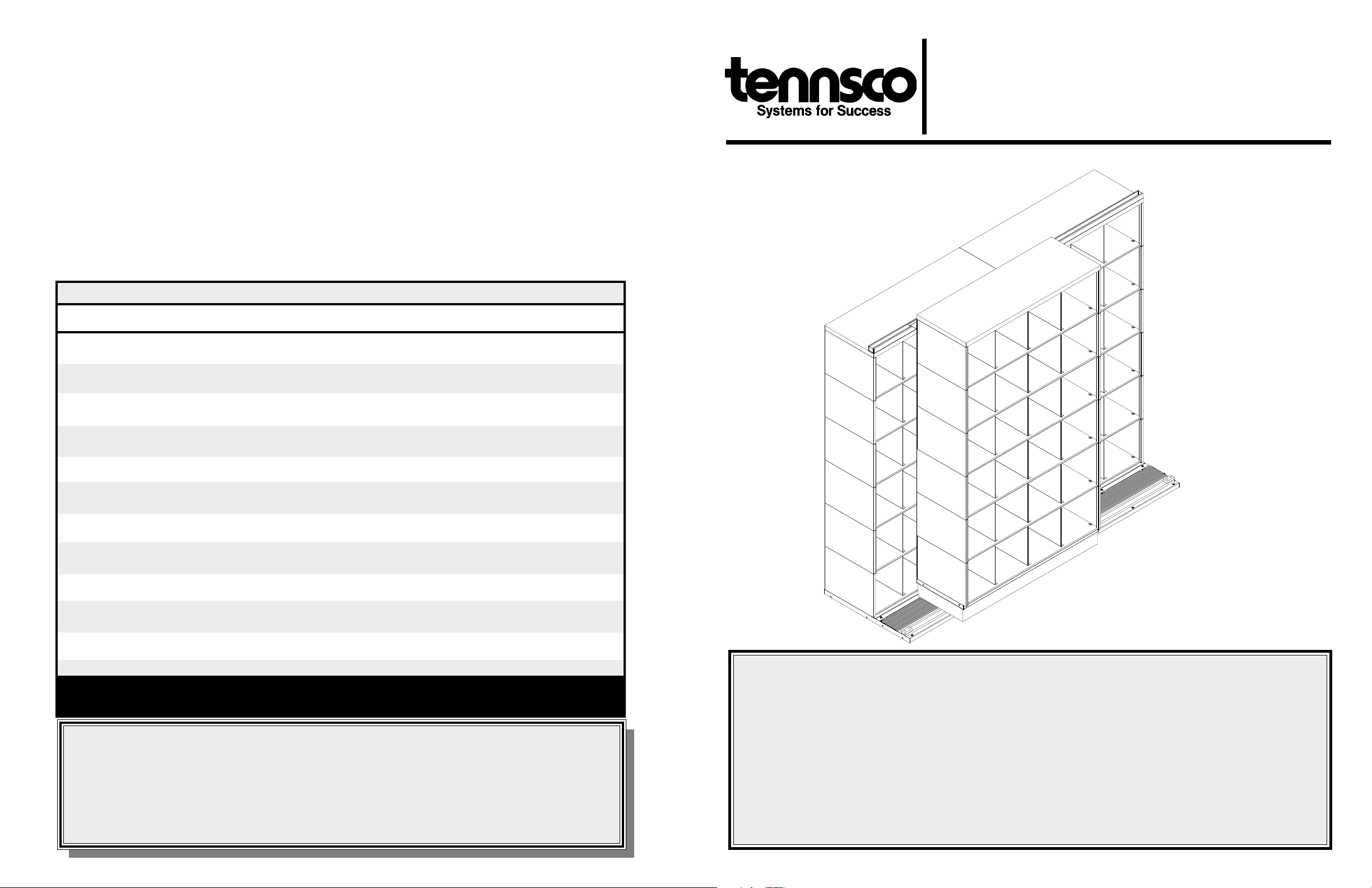
PART LIST FOR ADD-A-TRACK
REF. NO. DESCRIPTION QUANTITY
1 Leveling Screw 5/16-18 X 1" 16
2 Track Assembly 2
3 Floor Plate 4
4 Roll Pin 2
5 Track Splice Channel 1
3
6 10-32 x 1
7 10-32 Hex Nut 2
8 Rubber Bumper 2
9 Deck Cover ( for Track Assembly ) 2
10 Track End Plate 2
11 End Plate Angle 2
12 #14 Machine Screw 8
13 Top Track 2
14 8-32 x 1/2 Hex Head Machine Screw 10
15 8-32 Plate Nut 10
16 Base of ADD-A-STACK *not included with ADD-A-TRACK system
17 Mobile Carriage 1
18
19
1
/4-20 x 1 1/2 Hex Head Bolt 12
1
/4-20 Hex Nut 12
20 Stabilizer Roller Bracket Assembly for middle unit 1
21
1
/4-20 x 1/2 Bolt 4
22 Spacer 2
23 Stop Angle 2
We make every effort to ensure that all units ship complete and arrive undamaged. However, should your
unit contain missing or damaged parts, replacements may be obtained directly from us. To obtain proper
replacement parts, follow the instructions below, or fill out the form at www.tennsco.com/partsorder.html.
TO OBTAIN PROPER REPLACEMENT PARTS, PLEASE PROVIDE THE FOLLOWING INFORMATION:
●●
●
●●
Model Number Purchase Date
●●
●
●●
Description of part(s) needed and part Your company name
number(s) as shown in Parts List (above) Contact person's name
●●
●
●●
Color (i.e. Medium Grey, Sand, etc.) Company the product was purchased from
●●
●
●●
Was item missing, or was it damaged?
Tennsco Corp., P.O. Box 1888, Dickson, TN 37056-1888 E-mail address: info@tennsco.com
Customer Service: (866) 446-8686 Fax: (866) 445-7260
If requesting parts by telephone, ask for customer service and have as much of the above information ready as possible.
/4 Hex Head Screw 2
●●
●
●●
●●
●
●●
●●
●
●●
●●
●
●●
ASSEMBLY INSTRUCTIONS & PARTS MANUAL #2241205
ADD-A-TRACK BI-FILE SYSTEM
FOR USE WITH ADD-A-STACK SHELVING
Tennsco Corp., Dickson, TN 37056-1888 • (615) 446-8000
RETAIN INSTRUCTIONS FOR FUTURE REFERENCE!
LIMITED WARRANTY
Tennsco warrants goods purchased hereunder to be free of defects in materials and workmanship for a period of one (1) year from the date of shipment, hereunder.
This warranty shall not apply in the event goods are damaged as a result of misuse, abuse, neglect, accident, improper application, modification or repair by
persons not authorized by Seller, where goods are damaged during shipment, or where the date stamps on the goods have been defaced, modified or removed.
UNLESS CONSIDERED UNENFORCEABLE OR UNLAWFUL UNDER APPLICABLE LAW:
a. ALL IMPLIED WARRANTIES, INCLUDING BUT NOT LIMITED TO WARRANTIES OR MERCHANTABILITY AND FITNESS FOR A PARTICULAR
PURPOSE ARE HEREBY EXCLUDED:
b. BUYERS REMEDY, IF ANY, FOR ANY DEFECTIVE GOODS SHALL BE LIMITED TO A REFUND BY SELLER OR REPLACEMENT OF THE GOODS
AT SELLER’S OPTION, AND SHALL IN NO EVENT INCLUDE DAMAGES OF ANY KIND, WHETHER INCIDENTAL, CONSEQUENTIAL OR
OTHERWISE.
NO GOODS ACCEPTED FOR RETURN WITHOUT PRIOR APPROVAL. Seller shall have the right to inspect any goods claimed to be defective at Buyers place
of business or require Buyer to return the goods to Seller for inspection on Seller’s premises. Transportation charges covering returned goods will be borne
by Seller only if such goods are proven to be defective, are covered by this warranty and are returned within the warranty period stated above.
TENNSCO Corp., P.O. BOX 1888, DICKSON, TN 37056-1888
(615) 446-8000 or (866) 446-8686 (toll free)
Website: www.tennsco.com E-mail: Info@tennsco.com
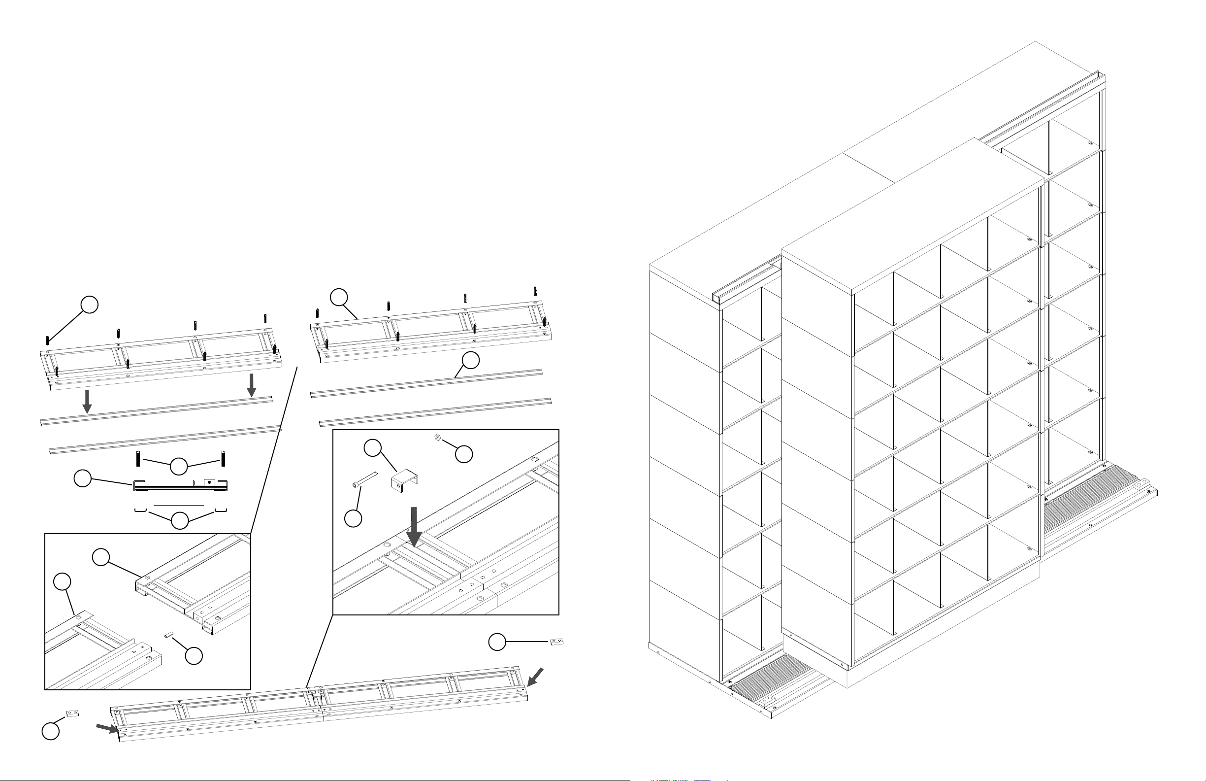
STEP 1) Locate the Leveling Screws (#1) (a quantity of 8 will be required for the 36" units, and 10 for the 48").
Thread them into the Track Assembly (#2) through the weld nuts with the socket facing up. Adjust all screws into
their upper most position. Continue this procedure until each Track Assembly in the system is complete.
STEP 2) Locate the Floor Protecting Channels (#3) on the floor with the “U” facing up; two (2) will be needed for each
Track Assembly. Approximate the position for the Floor Protector Channels (#3) and lay them in place. Next lay the
Track Assemblies on top of the channels. The leveling screws should be directly on top of the channels.
STEP 3) Locate the Roll Pin (#4) and drive it into the hole drilled at the end of each track. This is designed to fit very
tightly and will require a ball peen hammer. The opening will only permit the Roll Pin to be driven in partially; the
remaining portion of the Roll Pin will fit into the opening in the next Track Assembly. Position the next Track Assembly in place; make sure you have a tight fit to insure smooth operation.
STEP 4) Once you have joined the Track Assemblies together, locate the Track Splice Channel (#5). Install the
Track Splice Channel over the flange at the rear of the Track Assembly and secure using a 10 - 32 x 1 3/4 hex head
screw (#6), external tooth lock washer, and 1/4 x 20 hex nut (#7). Tighten firmly making sure that each track is
secure to the next.
STEP 5) Install the Rubber Bumpers (#8) at the end of each Track Assembly run, using two- (2) 1/4 x 1/2 self-tapping
screws. If these are not installed the carriage will roll off the end of the track.
1
2
3
5
7
1
2
End View
3
6
2
2
8
4
8
Completed ADD-A-TRACK System

23
23
20
13
13
STEP 9) Lay Top Track (#13) on top of the unit and drill two holes through the Top of the unit, locate the track flush with the
front edge of the shelving top. Place the Stop Angle (#23) at each end of the shelving run and bolt through it to attach the
Top Track to the shelving top.
STEP 10) Next attach the base of the unit (#16) to the top of the Mobile Carriage (#17) using four (4) 1/4 - 20 x 1 bolts (#18),
and 1/4 - 20 hex head nuts (#19). Once the base is attached to the carriage lift a completed section of levels and attach it to
the base that is attached to the carriage.
STEP 11) Repeat step 11 for each unit to be mounted on a Mobile Carriage.
16
STEP 12) Lift the unit and mobile carriage on top of the solid steel square rod on the track assembly, the steel wheel of
the carriage will roll on this steel square rod. The carriage does not roll on anything but the solid steel rod.
STEP 13) Next slide the Stabilizer Roller Bracket Assembly (#20) into the Top Track. Hold the Stabilizer Roller Bracket
Assembly against the back panel of the front unit and mark where the holes will need to be drilled to attach the bracket.
STEP 14) Next attach the bracket (#20) to the unit and check to see if the unit rolls freely on the steel track. The steel
wheel of the carriage will roll on the square steel bar in the floor assembly.
except the steel bar. Some adjust
unit is level and plumb before using. Recheck all bolts for tightness.
ment may be needed to the brackets for a smooth free operation. Make sure the mobile
Do not have the carriage rolling on any surface
End view of Front Unit
23
13
17
18
End view of Rear Unit
19
End view of Rear Unit
End view of Front Unit
9
End View
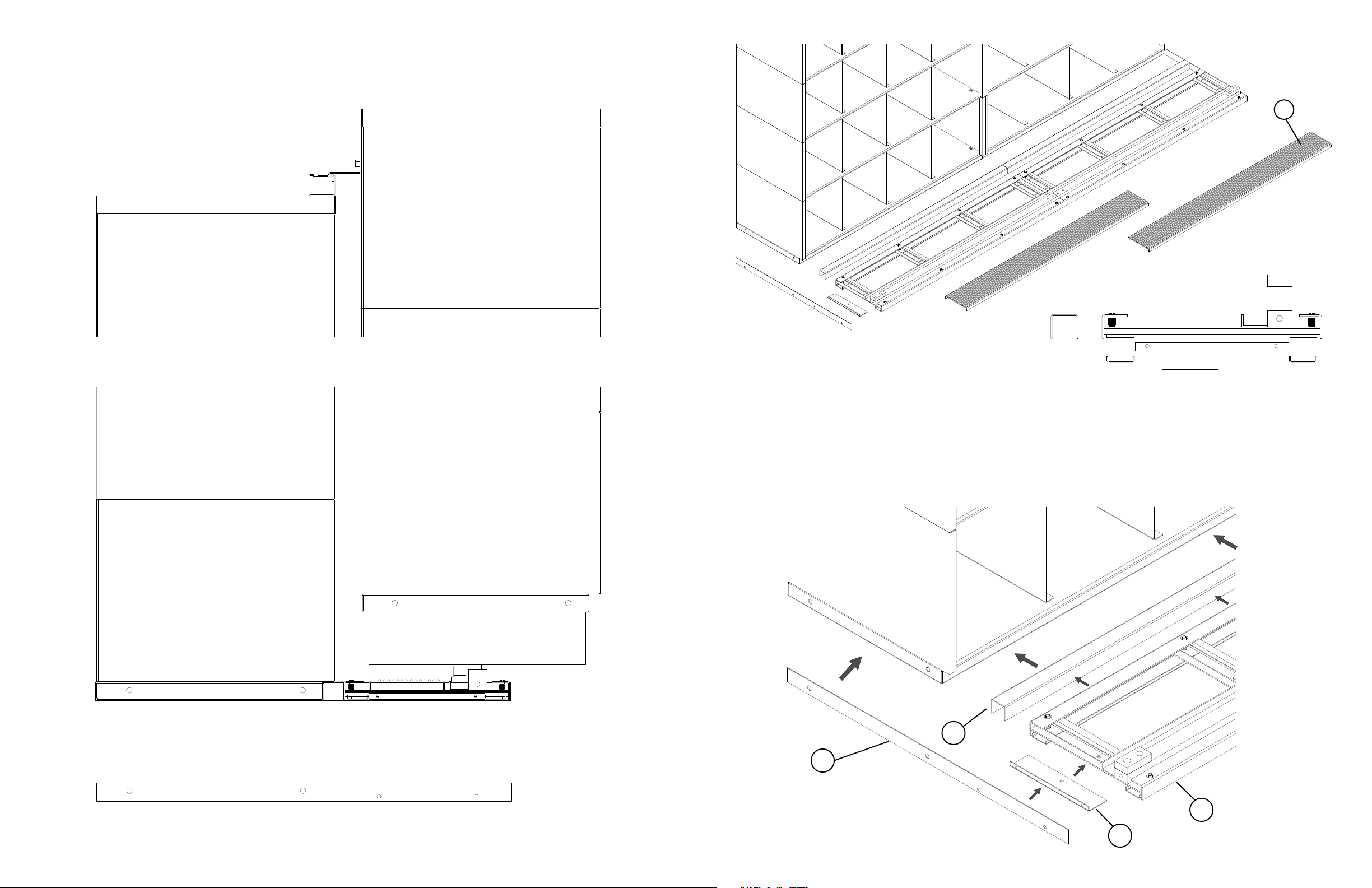
STEP 6) Attach End Plate Angle (#14) to track assembly using one bolt and nut as shown.
STEP 7) Place Spacer in front of stationary unit, locate track assembly(#2) in front of unit and flush with end of unit. At
both ends of the floor assembly, attach one end of the Track End Plate (#13) to the End Plate Angle (#14) using two (2)
machine screws (#15). Then attach this assembly to the end of the shelving. This will insure that this floor assembly
does not move.
STEP 8) Place the Deck Covers (#9) into the open portion of the Track Assembly. They are approximately 6" x 36" or
48" and have a ribbed safety vinyl laminated to the surface.
22
10
END VIEW OF UNITS AFTER THEY ARE COMPLETED
2
11
 Loading...