

Tennsco 1870, 1871, 1872, 2470, 2471 Assembly Instructions Manual
...
ASSEMBLY INSTRUCTIONS & PARTS MANUAL #1220497
DELUXE UNASSEMBLED CABINETS
Models 1870,1871,1872,
2470, 2471, 2472
Tennsco Corp., Dickson, TN 37056-1888 (615) 446-8000
READ INSTRUCTIONS CAREFULLY BEFORE ATTEMPTING TO ASSEMBLE YOUR CABINET.
RETAIN INSTRUCTIONS FOR FUTURE REFERENCE!
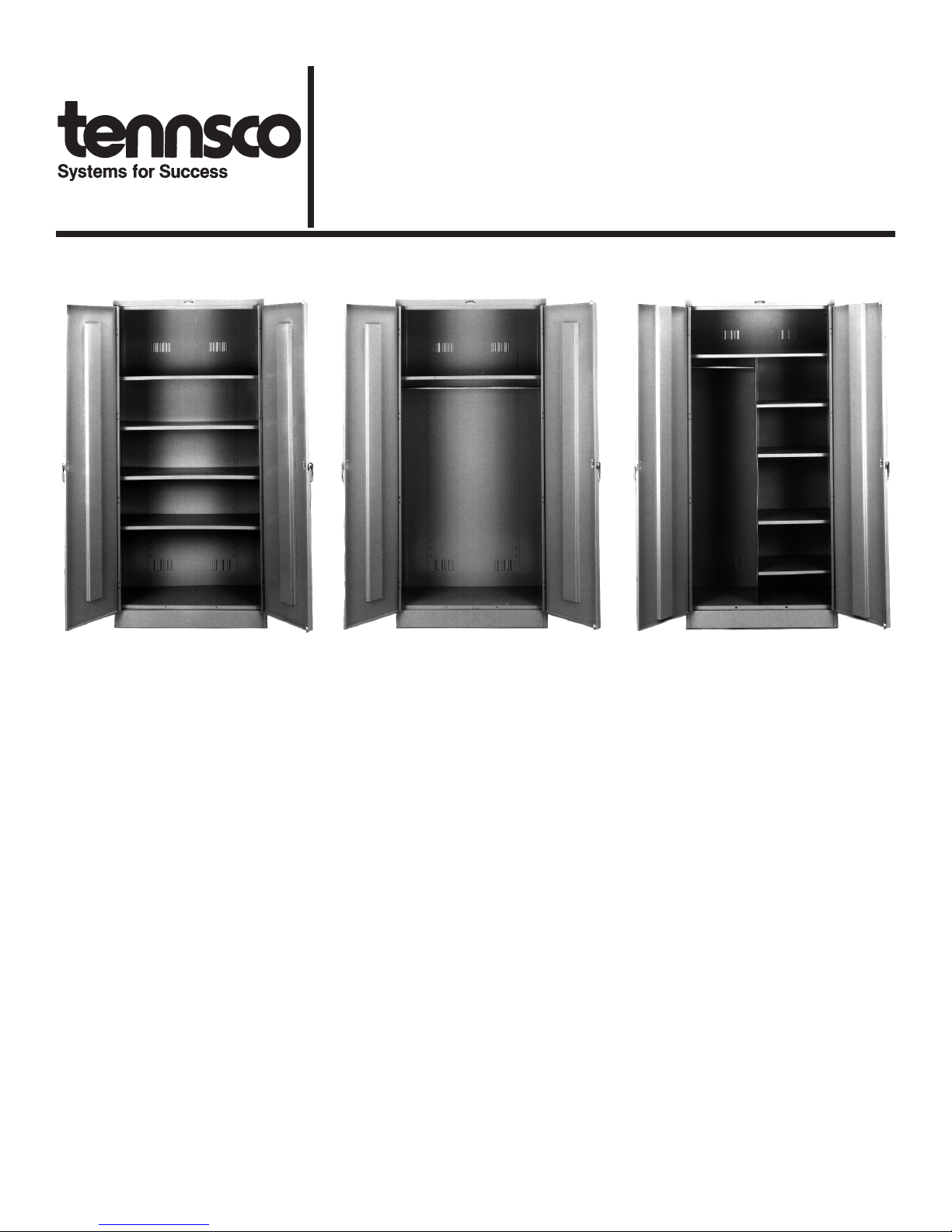
Deluxe Storage Cabinet
Models 1870 & 2470
Deluxe Wardrobe Cabinet
Models 1871 & 2471
DESCRIPTION
Tennsco cabinets are designed for use in offices, schools,
institutions, businesses and industrial storerooms. They provide secure storage for office supplies, books, records, small
parts, tools, office machines, etc. Our convenient built-in
handle lock with 2 keys and three point locking system
provide extra security. Nylon lock-bar guides ensure quiet
operation. And built-in levelers make the final positioning of
your cabinet an easy task.
Tennsco's heavy-guage steel construction with baked-on
enamel finish assures you years of trouble-free service, even
under the most demanding situations. Many unique features
not found on other cabinets make our Deluxe Line the most
efficient, durable and convenient cabinet you can use.
Models 1870 & 2470 have five openings with adjustable
shelves. Models 1871 & 2471 are wardrobe style cabinets
with a 36" coat rod and a hat shelf. Models 1872 & 2472 are
combination wardrobe and storage cabinets.
Deluxe Combination Cabinet
Models 1872 & 2472
SPECIFICATIONS
Overall Dimensions:
Models 1870, 1871 & 1872: ............... 36"w x 18"d x 78"h
Models 2470, 2471 & 2472: ............... 36"w x 24"d x 78"h
Basic Construction:
All models are constructed with 16 gauge steel frames, 22
gauge steel sides, back, top, bottom and shelves, and 20
gauge steel doors.
Weight (approximate):
Model 1870 ......................................................... 156 lbs.
Model 2470 ......................................................... 188 lbs.
Model 1871 ......................................................... 140 lbs.
Model 2471 ......................................................... 160 lbs.
Model 1872 ......................................................... 159 lbs.
Model 2472 ......................................................... 187 lbs.
Colors: ........................... Black, Sand, Champagne Putty,
.............................................. Light Grey & Medium Grey
GENERAL SAFETY INSTRUCTIONS
1. Some parts may have sharp edges. CARE must be taken when handling various pieces to avoid injury.
2. For safety, wear a pair of work gloves when assembling or performing any maintenance on your cabinet.

ASSEMBLY INSTRUCTIONS
(Refer to Figures 1, 2, and 3)
Do not tighten bolts until cabinet is completely assembled.
Tools required: Rubber mallet, slotted screwdriver, 11/32" nut driver
(11/32" socket may be substituted).
ALL MODELS
1. Place back (Ref. No. 1) on either padded
horses or on protected floor so the flange is
upward.
2. Attach sides (Ref. Nos. 2 & 3) to back by
placing side with flange around back and
bolting together with slotless #8-32 x 3/8"
bolts and nuts. Be certain that all shelf adjustment strips are pointed in the same direction.
3. Place a shelf (Ref. No. 7) into shelf adjustment
strips to hold sides in upright position. Be sure
channeled edge of shelf is to the front.
4. Locate top which has the holes along the
perimeter (Ref. No. 4). Place top, with two
holes toward front, under flanges at top of
sides and back. Bolt together.
5. Place door and frame assembly (Ref. No. 6)
over body.
6. Bolt sides to frame.
7. Place bottom (Ref. No. 5) in lowest notch of
shelf adjusting strips on sides and back so that
the flange with two holes faces the front and is
over the flange of frame sill. Push out on side
wall to enable bottom to more easily slide into
position.
8. Bolt bottom to frame sill.
MODELS 1870 AND 2470
9. Using a rubber mallet, place adjustable
shelves in desired position with channeled
edge toward front and press end and back
flanges into notches of shelf adjusting strips.
10. Stand unit upright.
MODELS 1871 AND 2471
11. Remove shelf from cabinet and place coat rod
bracket (Ref. No. 8) over each end and bolt
brackets to shelf. Place coat rod (Ref. No. 9)
into position. Replace shelf in top adjustment
notch.
12. Stand unit upright.
MODELS 1872 and 2472
13. Remove full shelf from cabinet and place coat
rod bracket (Ref. No. 8) over left end and
fasten with nut and bolt. Replace shelf in top
adjustment notch.
14. Install partition (Ref. No. 11) into place with
hemmed edge to front and shelf adjustment
strip facing the right side of cabinet. Secure
with nuts and bolts.
15. Place remaining bracket over coat rod (Ref.
No. 8) and slide end of coat rod through the
previous attached bracket. Align holes in
bracket and shelf and secure with nut and bolt.
16. Using rubber mallet, place adjustable partition
shelves in desired position with channeled
edge toward front and press end and back
flanges into notches of shelf adjusting strips.
ALL MODELS (CONTINUED)
17. Tighten all hardware.
18. Be sure cabinet is level. Place a screwdriver
through the hole in each end of the sill and
adjust the leveling screw until cabinet is level.
19. Install locking mechanism as follows (Refer to
Door Lock Detail):
a. Place locking handle (Ref. No. 13) on right
hand door and fasten with #8-32 bolts with
lockwashers.
b. Turn handle to open position and place
locking cam (Ref. No. 14) over square
shank of door handle with latch facing
downward.
c. Hook locking bars (Ref. No. 12) to locking
cam and hold in position while sliding nylon
lock bar guide inserts (Ref. No. 16) over
door lock bar and through door slots.
d. Place locking cam retainer (Ref. No. 15)
over square shank of door handle and drive
into place.
20. Place dummy handle on left hand door and
fasten with bolts with lock washers.
 Loading...