

Tennsco 1472 User Manual
ASSEMBLY INSTRUCTIONS & PARTS MANUAL #1760608
TENNSCO COMBINATION CABINET
Model 1472
Tennsco Corp., Dickson, TN 37056-1888 (615) 446-8000
RETAIN INSTRUCTIONS FOR FUTURE REFERENCE!
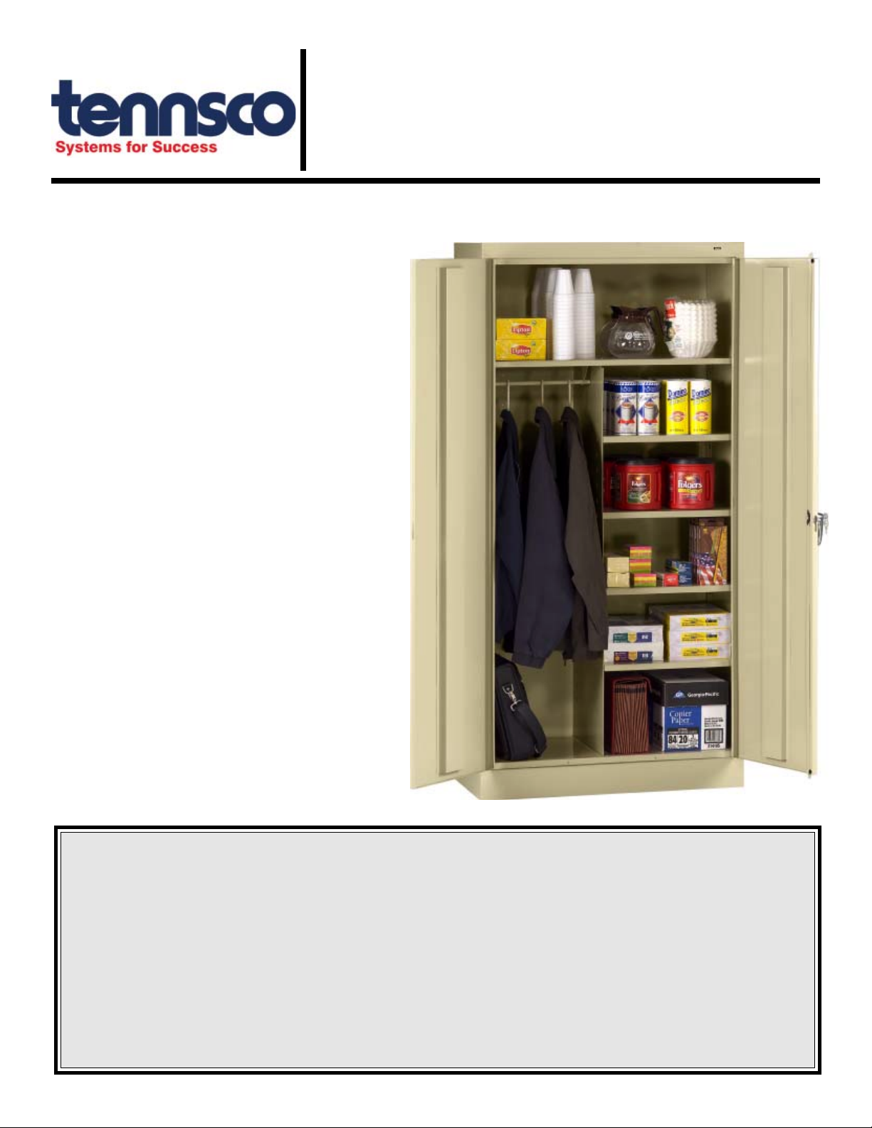
Congratulations on your purchase of a
Tennsco Combination Cabinet! Tennsco's
1472 units provide a level of quality you won't
find elsewhere. They provide secure storage
with a hanging rod for jackets, clothing, and
other hanging garments, along with shelves
along one side and at the top for hats,
books, tools, and other general storage.
These cabinets also offer a locking chrome
handle with two keys, and a three-point
locking system for extra security.
Tennsco's cabinets are constructed from top
quality 22 to 24 gauge steel, with 22 gauge
steel shelves, offering weight capacities of up
to 200 lbs. per shelf (evenly distributed). Our
attractive and durable powder-coated paint
finish will provide for years of service.
GENERAL SAFETY INFORMATION
Some parts may have sharp edges. CARE must
be taken when handling various pieces to avoid
injury. For safety, wear a pair of work gloves
when assembling or performing any maintenance on your cabinet.
LIMITED WARRANTY
Tennsco warrants goods purchased hereunder to be free of defects in materials and workmanship for a period of one (1) year from the date of shipment, hereunder.
This warranty shall not apply in the event goods are damaged as a result of misuse, abuse, neglect, accident, improper application, modification or repair by persons
not authorized by Seller, where goods are damaged during shipment, or where the date stamps on the goods have been defaced, modified or removed. UNLESS
CONSIDERED UNENFORCEABLE OR UNLAWFUL UNDER APPLICABLE LAW:
a. ALL IMPLIED WARRANTIES, INCLUDING BUT NOT LIMITED TO WARRANTIES OR MERCHANTABILITY AND FITNESS FOR A PARTICULAR PURPOSE
ARE HEREBY EXCLUDED:
b. BUYERS REMEDY, IF ANY, FOR ANY DEFECTIVE GOODS SHALL BE LIMITED TO A REFUND BY SELLER OR REPLACEMENT OF THE GOODS AT
SELLERS OPTION, AND SHALL IN NO EVENT INCLUDE DAMAGES OF ANY KIND, WHETHER INCIDENTAL, CONSEQUENTIAL OR OTHERWISE.
NO GOODS ACCEPTED FOR RETURN WITHOUT PRIOR APPROVAL. Seller shall have the right to inspect any goods claimed to be defective at Buyers place
of business or require Buyer to return the goods to Seller for inspection on Sellers premises. Transportation charges covering returned goods will be borne by
Seller only if such goods are proven to be defective, are covered by this warranty and are returned within the warranty period stated above.
TENNSCO Corp., P.O. BOX 1888, DICKSON, TN 37056-1888
(615) 446-8000 or (866) 446-8686 (toll free)
Website: www.tennsco.com E-mail: Info@tennsco.com
PK-1760608
ASSEMBLY OF 1472 CABINETS
Tools Needed: A free 11/32" nut driver is provided with each Tennsco cabinet (Ref. No. 21). In addition,
you will need a flathead screwdriver. A hammer is required to install the hinge pin and lock bar.
Two people recommended for assembly. Approximate assembly time: 15 to 25 minutes.
1. Reference numbers are there to help you identify
the various parts as they are mentioned, and refer
to the illustration on the back cover.
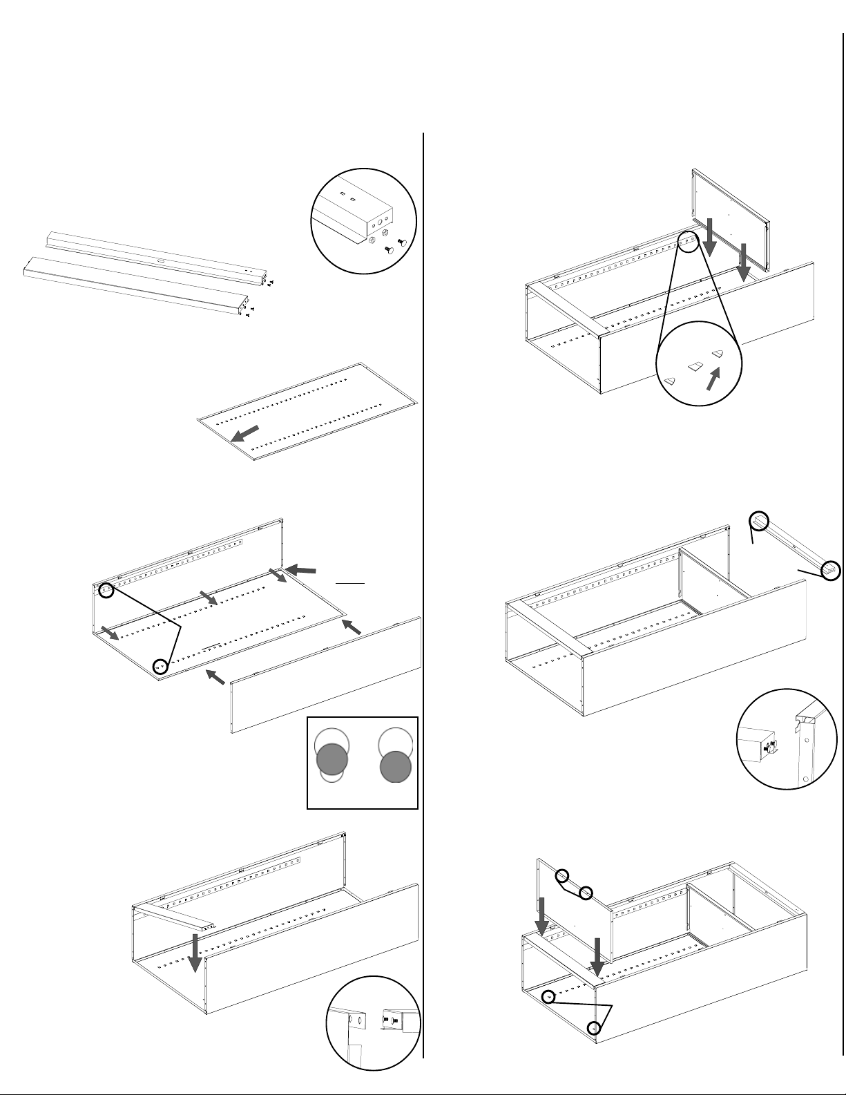
2. Prepare the header (Ref. No. 5) for
installation by inserting a bolt into
the two outside holes on
Sill
Header
each end, as
shown in
Inset A. The
Inset A
center
hole should remain empty. Loosely attach
nuts to each bolt, leaving enough slack so the
bolt heads may later be inserted into a
slot. Prepare
the sill (Ref. No. 6) in the same way.
3.
Place the cabinet back (Ref. No. 1)
on a protected
to
prevent
the paint
surface
scratching
. The flange on
Flange faces upward
the bottom of the back should be facing upward.
4. Attach the left side (Ref. No. 2) to the back by
placing flange (A) around the back and bolting
the pieces together with
seven bolts and
nuts (Ref.
Nos.
18 &
19).
Be
All lances point UP
B
on the back
and both sides.
sure that
the lances
on all shelf adjustment
strips (B) point in the
same direction. Attach
the right side in exactly
the same manner.
5.
Locate the two keyhole-shaped slots on
the front of each end-panel bottom.
No. 6) by inserting the loose bolt
heads (which
you
attached to
the sill in step 2) into
the large end
of the keyhole slots
(Inset B).
Position by
sliding the bolts
securely into the
smaller
end of the
slots. Inset C
right) shows improper and proper seating
boltheads.
Tighten the four nuts
Attach the sill (Ref.
(above
securely.
A
Improperly
seated
of
Flange tucks
under back
Inset C
Properly
seated
Inset B
6. Insert
position
Do this by inserting
the shelf
on the
(Ref. No. 4) into the top
shelf adjustment strips.
the shelf edges
into the lances on all four strips.
Be sure
that the channeled edge
of the shelf is toward the
cabinet front. If a
lance is too
tight, it
may be
helpful to
use a
screwdriver
to SLIGHTLY
pry it open.
7. Locate the two keyhole-shaped slots on the top
front of each end-panel. Attach the header (Ref.
No. 5) in the same way you attached
the sill, by inserting the previously
attached loose bolt heads
into the large end
of the key-
Two bolts
and nuts on
each side
hole
slots
(Inset D)
.
Position
by sliding
the bolts
securely into the
smaller
end of the
slots. Refer to Inset C
Inset D
(in step 6 above) for improper and
proper
seating
of the boltheads. Tighten
the four nuts securely.
8. Place the bottom (Ref. No. 7) in the bottom
lances of the
strips. The
flange with
two holes
should
face the
front, and
it should
hang over the
sill. Bolt to the
sill with two bolts and nuts.
shelf adjustment
Two holes must
be in front.
Insert shelf into
bottom lances.
 Loading...