

Tennant T350 Users guide
T350
Stand-On Rider Scrubber
English EN
Operator Manual
Hygenic® Fully Cleanable Recovery Tank
Tennant True® Parts
®
a Tennant Technology
IRIS
Pro-Panel® Controls
Smart-Fill™ Automatic Battery Watering
Insta-Click™ Magnetic Disk
North America / International
For the latest Parts Manuals and other
language Operator Manuals, visit:
www.tennantco.com/manuals
R
9016417
Rev. 01 (02-2021)
*9016417*
INTRODUCTION
INTENDED USE
This manual is available for each new model. It provides
necessary operation and maintenance instructions.
Read this manual completely and
understand the machine before
operating or servicing it.
This machine will provide excellent service. However, the
best results will be obtained at minimum costs if:
• The machine is operated with reasonable care.
• The machine is maintained regularly - per the
maintenance instructions provided.
• The machine is maintained with manufacturer supplied or
equivalent parts.
To view, print or download manuals online visit
www.tennantco.com/manuals
PROTECT THE ENVIRONMENT
Please dispose of packaging materials
and used machine components such as
batteries in an environmentally safe way
according to your local waste disposal
regulations.
The T350 stand-on rider fl oor scrubber is intended for
commercial use, for example in hotels, schools, hospitals,
factories, shops, offi ces and rental businesses. It is
designed to scrub hard fl oor surfaces (concrete, tile, stone,
synthetic, etc.) in an indoor environment. This machine is
not intended for cleaning carpets. Use only recommended
pads/brushes and commercially available fl oor cleaning
detergents. Do not use this machine other than described
in the Operator Manual.
MACHINE DATA
Please fi ll out at time of installation for future reference.
Model No. -
Serial No. -
Installation Date -
MACHINE SERIAL NUMBER LOCATION
Always remember to recycle.
Tennant Company
10400 Clean Street
Eden Prairie, MN 55344-2650
Phone: (800) 553-8033
www.tennantco.com
1-STEP, Pro-Membrane, Severe Environment, Zone Settings, and
Quiet-Mode are trademarks of Tennant Company.
Trojan® and HydroLINIK® are registered trademark of Trojan Battery
Company.
Windows 7® is a registered trademark of the Microsoft Corporation.
This product may contain portions of software that have various 3rd party
licenses. More information can be found at:
www.tennantco.com/opensource
Specifi cations and parts are subject to change without notice.
Original Instructions, copyright 2017, 2021 TENNANT Company.
UNCRATING MACHINE
Carefully check machine for signs of damage. Report
damages at once to carrier. Contact distributor or Tennant
for missing items.
To uncrate the machine, remove straps, wheel blocks and
shipping brackets. Using the supplied ramp carefully back
the machine off the pallet. Make sure scrub head is in the
raised position.
ATTENTION: Do not remove machine from pallet
without using ramp, machine damage may occur.
ATTENTION: Due to the center of gravity being higher
(making it easier to tip machine) for machines without
batteries installed, use care when uncrating the
machine if it does not have batteries installed. Install
batteries before moving machine from pallet.

CONTENTS
CONTENTS
Introduction .....................................................2
Intended Use ...................................................2
Machine Data ..................................................2
Machine Serial Number Location ...............2
Uncrating Machine ..........................................2
Contents ................................................................3
Important Safety Instructions - Save These
Instructions ............................................................6
Operation .............................................................10
Machine Components ...................................11
Scrub Head Types.........................................11
Control Panel Components ...........................12
Pro-Membrane Control Panel Model ....12
Pro-Panel Control Model .......................13
Machine Symbols. .........................................14
Pro-Panel Symbols .......................................15
Installing Batteries .........................................16
Battery Specifi cations ...........................16
How The Machine Works ..............................17
Brush And Pad Information ...........................17
Machine Setup ..............................................18
Attaching Squeegee Assembly ................18
Installing Brushes / Pads ..........................19
Filling Solution Tank .................................20
Filling Severe Environment Detergent
Tank (Ec-H2o Model Option) ...............21
Ec-H2o Water Conditioning Cartridge
(Ec-H2o Model) ...................................22
Filling Automatic Battery Watering Tank
(Option) ...............................................23
Control Panel Operation ...............................24
Operation Of Controls -
Pro-Membrane Controls ......................24
1-Step Button ........................................24
Brush Pressure Button ..........................24
Solution Flow Button .............................24
Quiet-Mode Button (Option) ..................24
Severe Environment Button
(Ec-H2o Model Option) ....................25
Preset Zone Control Buttons .................25
Ec-H2o Button / Indicator (Option) ........26
Service Indicator ...................................26
Battery Discharge Indicator ...................26
Automatic Battery Watering Indicator
(Option) ............................................26
Brush Change Button ............................27
Vacuum Fan Button ..............................27
Operation Of Controls -
Pro-Panel Controls ..............................28
Home Screen ........................................28
Help Button ...........................................28
Login Screen .........................................28
Ec-H2o Indicator (Option) .....................29
1-Step Button ........................................29
Vacuum Fan Button ..............................29
Brush Pressure Button ..........................29
Solution Flow Button .............................30
Brush Change Button ............................30
Severe Environment Button
(Ec-H2o Model Option) ....................30
Quiet-Mode Button (Option) ..................31
Battery Discharge Indicator ...................31
Video Tutorial Button
(Operator Mode Home Screen) .......31
Preset Zone Control Buttons .................31
Service Indicator Button ........................32
Fault Screens ........................................32
Machine Operation ........................................34
Pre-Operation Checklist ...........................34
Operating Machine ...................................34
Double Scrubbing .....................................36
Emergency Shut-Off Button .....................37
While Operating Machine .........................37
Circuit Breaker Panel ...............................38
Hour Meter ...............................................38
Draining Tanks ..............................................39
Draining Recovery Tank ...........................39
Draining Solution Tank .............................40
Service Indicator Codes ................................41
On-Board Battery Charger Service
Indicator Codes ...................................42
Ec-H2o System Service Indicator Codes
(Option) ...............................................43
Maintenance ........................................................44
Maintenance Chart ...................................44
Machine Maintenance ...................................46
Yellow Touch Points ......................................46
After Daily Use .........................................46
After Weekly Use .....................................48
After Every 50 Hours Of Use ....................49
After Every 100 Hours Of Use ..................49
After Every 200 Hours Of Use ..................49
Electric Motors .........................................49
T350 9016417 (02-2021)
3

CONTENTS
Batteries ........................................................50
Maintenance-Free Batteries .....................50
Flooded (Wet) Lead-Acid Batteries ..........50
Checking Connections / Cleaning ............50
Charging Batteries ...................................51
Battery Charger Settings ..........................52
Changing On-Board Battery Charger
Settings (Pro-Membrane Model) ......52
Hydrolink® Battery Watering System
(Trojan® Battery Option) .....................54
Manual Battery Watering System
(Trojan® Battery Option) .....................55
Smart-Fill Automatic Battery Watering
(Option) ...............................................57
Battery Compartment Drain Valve ............58
Brush And Pad Replacement ........................59
Replacing Brush(Es) Or Pad(S) On
Pro-Panel Machines ............................59
Replacing Brush(Es) Or Pad(S) On
Pro-Membrane Panel Machines ..........61
Squeegee Blade Replacement .....................62
Replacing Squeegees On Machines With
20 In. (500 Mm) Scrub Heads .............62
Replacing Squeegees On Machines With
24 In. (600 Mm) Scrub Heads .............64
Ec-H2o Water Conditioning Cartridge
Replacement ..........................................66
Machine Jacking ...........................................67
Jacking Up The Front Of The Machine ....68
Jacking Up The Rear Of The Machine .....68
Pushing, Towing, And T ransporting The
Machine ..................................................69
Pushing And Towing The Machine ...........69
Transporting The Machine .......................69
Storing Machine ............................................70
Freeze Protection .....................................70
Machine Troubleshooting ..............................72
General Machine Dimensions/Capacties/
Performance ........................................................74
Supervisor Controls .............................................77
Pro-Membrane Control Panel Model ............77
Entering The Supervisor Control
Modes ..............................................77
Pro-Panel Controls Model .............................79
Entering The Supervisor Mode .............79
To Add / Edit Profi les .............................80
Enabling The Login Screen ...................82
Disabling The Login Screen ..................83
Changing The Factory-Assigned
Supervisor Login Code ....................84
Changing The Scrub Speed ..................85
Changing Preset Zone Control
Buttons .............................................85
Changing The On-Board Battery
Charger Settings
(Pro-Panel Model) ............................86
Calibrating The Touch ...........................86
4
T350 9016417 (02-2021)

CONTENTS
T350 9016417 (02-2021)
5

SAFETY
IMPORTANT SAFETY INSTRUCTIONS - SAVE THESE INSTRUCTIONS
The following precautions are used throughout this
manual as indicated in their descriptions:
WARNING: To warn of hazards or
unsafe practices that could result in
severe personal injury or death.
FOR SAFETY: To identify actions that must be
followed for safe operation of equipment.
The following information signals potentially
dangerous conditions to the operator. Know
when these conditions can exist. Locate all safety
devices on the machine. Report machine damage
or faulty operation immediately.
WARNING: To Reduce the Risk of Fire,
Explosion, Electric Shock or Injury:
- Read manual before operating machine.
- Do not use or pick up fl ammable materials
or reactive metals.
- Do not use near fl ammable liquids, vapors
or combustible dusts.
This machine is not equipped with an
explosion proof motor. The electric
motor will spark upon start up and during
operation which could cause a fl ash fi re
or explosion if machine is used in an
area where fl ammable vapors/liquids or
combustible dusts are present.
- Batteries emit hydrogen gas. Explosion
or fi re can result. Keep sparks and open
fl ame away when charging.
- Disconnect battery cables and charger
cord before cleaning and servicing
machine.
- Do not charge batteries with damaged
cord. Do not modify plug.
If the charger supply cord is damaged
or broken, it must be replaced by the
manufacturer or its service agent or a
similarly qualifi ed person in order to avoid
a hazard.
- Do not use outdoors. Store indoors.
IRIS Telemetry - This machine may be
equipped with technology that automatically
communicates over the cellular network. If the
machine will be operated where cell phone use
is restricted because of concerns related to
equipment interference, please contact a Tennant
representative for information on how to disable
the cellular communication functionality.
FOR SAFETY:
1. Do not operate machine:
- Unless trained and authorized.
- Unless operator manual is read and
understood.
- Unless mentally and physically capable of
following machine instructions.
- Under the infl uence of alcohol or drugs.
- While using a cell phone or other types of
electronic devices.
- With brake disabled.
- If not in proper operating condition.
- With pads or accessories not supplied or
approved by Tennant. The use of other pads
may impair safety.
- In outdoor areas. This machine is for indoor
use only.
- In areas where fl ammable vapors/liquids or
combustible dusts are present.
- In areas that are too dark to safely see the
controls or operate the machine.
- In areas with possible falling objects.
- Do not place weights or heavy objects on
the operator presence pedal and/or green
go pedal.
2. Before Starting Machine:
- Check machine for fl uid leaks.
- Make sure all safety devices are in place
and operate properly.
- Check steering for proper operation.
3. When using machine:
- Use only as described in this manual.
- Do not pick up burning or smoking debris,
such as cigarettes, matches or hot ashes.
- Go slowly on inclines and slippery surfaces.
- Follow site safety guidelines concerning wet
fl oors.
- Do not scrub on inclines that exceed 9%
grade or transport on inclines that exceed
9% grade.
- Do not turn on inclines or ramps
- Reduce speed when turning.
- Keep all parts of body inside operator station
while machine is moving.
6
T350 9016417 (02-2021)

SAFETY
- Always be aware of surroundings while
operating machine.
- Always allow head clearance when going
through doorways, low ceilings, and
overhangs.
- Drive slowly through doorways and narrow
openings, especially with the dual disk
model as squeegee extends beyond width
of machine.
- Do not access the video / help screens while
the machine is moving. (Pro-Panel)
- Use care when reversing machine.
- Keep children and unauthorized persons
away from machine.
- Do not allow machine to be used as a toy.
- Do not carry passengers on any part of the
machine.
- Report machine damage or faulty operation
immediately.
- Follow mixing, handling and disposal
instructions on chemical containers.
- Follow site safety guidelines concerning wet
fl oors.
4. Before leaving or servicing machine:
- Stop on level surface.
- Turn off machine and remove key.
5. When servicing machine:
- All work must be done with suffi cient lighting
and visibility.
- Keep work area well ventilated.
- Avoid moving parts. Do not wear loose
clothing, jewelry and secure long hair.
- Block machine tires before jacking machine
up.
- Jack machine up at designated locations
only. Support machine with jack stands.
- Use hoist or jack that will support the weight
of the machine.
- Do not push or tow the machine without an
operator controlling the machine.
- Do not push or tow the machine on inclines
with the brake disabled.
- Do not power spray or hose off machine
near electrical components.
- Disconnect battery connections and charger
cord before working on machine.
- Do not use incompatible battery chargers
as this may damage battery packs and
potentially cause a fi re.
- Inspect charger cord regularly for damage.
- Do not plug in charger if prongs are wet.
- Open recovery tank to vent batteries if
temperature is above 80ºF/27ºC when
charging batteries.
- Do not disconnect the off−board charger’s
DC cord from the machine receptacle when
the charger is operating. Arcing may result.
If the charger must be interrupted during
charging, disconnect the AC power supply
cord fi rst.
- Avoid contact with battery acid.
- Always follow site safety rules when
disposing battery compartment liquid.
- Keep all metal objects off batteries.
- Use a non−conductive battery removal
device.
- Use a hoist and adequate assistance when
lifting batteries.
- Battery installation must be done by trained
personnel.
- Follow site safety guidelines concerning
battery removal.
- All repairs must be performed by trained
personnel.
- Do not modify the machine from its original
design.
- Use Tennant supplied or approved
replacement parts.
- Wear personal protective equipment as
needed and where recommended in this
manual.
For Safety: wear protective gloves.
For Safety: wear eye protection.
6. When loading/unloading machine onto/off truck
or trailer:
- Drain tanks before loading machine.
- Use a ramp that can support the machine
weight and operator.
- Do not drive on a slippery ramp.
- Do not operate the machine on a ramp
incline that exceeds an 18% grade level.
- Use a winch if ramp incline exceeds an 18%
grade level.
- Lower scrub head and remove squeegee
before tying down machine.
- Block machine tires.
- Tie machine down to truck or trailer.
T350 9016417 (02-2021)
7
SAFETY
The following safety labels are mounted on the
machine in the locations indicated. Replace
damaged / missing labels.
WARNING LABEL - Located on access panel.
WARNING LABEL - Electrical
hazard. Disconnect battery
cables before servicing
machine.
Located on on-board battery
charger mounting plate.
WARNING LABEL - Spinning
brush. Keep hands away.
Located on top of scrub head.
WARNING LABEL - Batteries emit
hydrogen gas. Explosion or fi re can
result. Keep sparks and open fl ame
away when charging.
Located on bottom of recovery tank.
1204364
WARNING LABEL - Magnetic Field Hazard.
Magnetic pad driver/brush can be harmful to
those with pacemakers or medical implants.
Located on Insta-Click magnetic pad driver/brush.
8
T350 9016417 (02-2021)

SAFETY
T350 9016417 (02-2021)
9
OPERATION
OPERATION
8
27
12
25
21 22
15
14
11
26
6
5
1
7
16
13
30
24
23
19
28
3
2
17
4
29
9
18
10
20
10
T350 9016417 (02-2021)
OPERATION
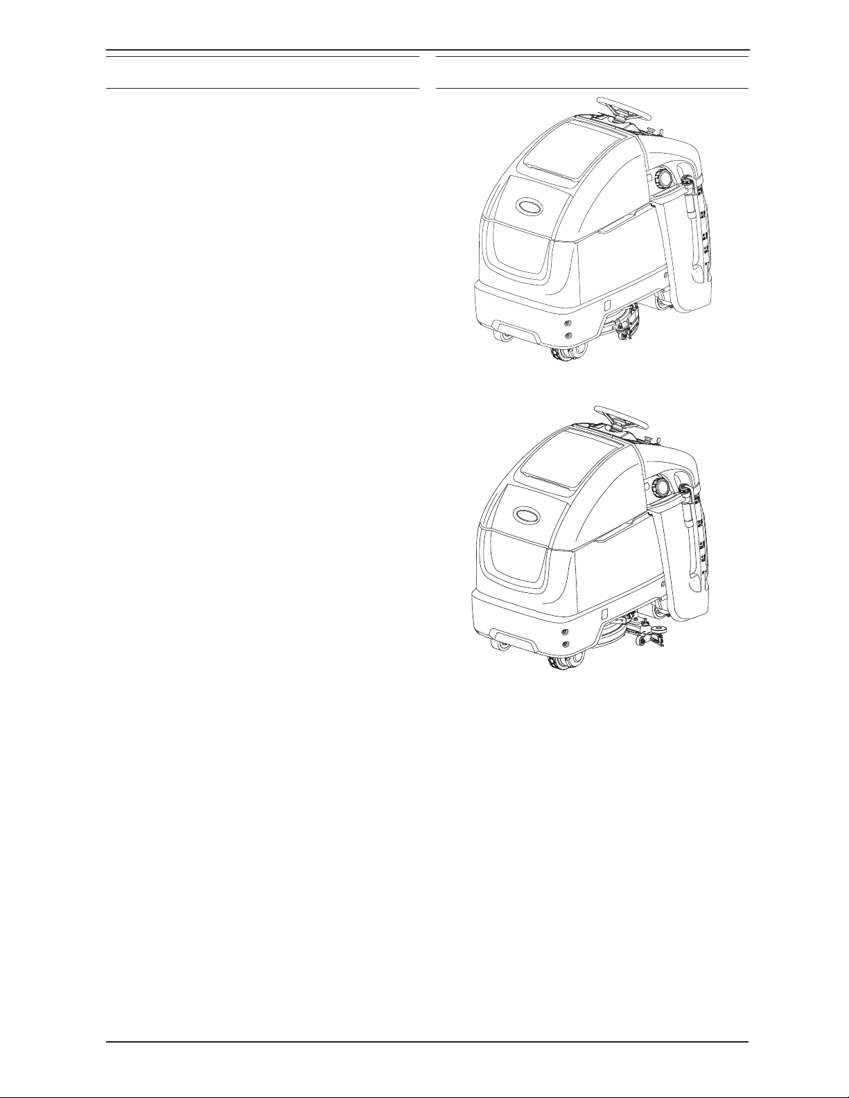
MACHINE COMPONENTS
1. Steering Wheel
2. Key switch
3. Forward / Reverse switch
4. Emergency shut-off button
5. Hour meter
6. Horn button
7. Control panel
8. Speed knob
9. Operator presence pedal
10. Green go pedal
11. Solution tank
12. Solution tank fi ll port
13. Solution tank level / drain hose
14. Recovery tank
15. Recovery tank cover
16. Recovery tank drain hose
17. Battery compartment
18. Automatic battery watering tank (option)
19. Severe Environment detergent tank
(option - with ec-H2O option only)
20. Detergent mixing ratio knob
(option - with ec-H2O option only)
21. ec-H2O module (option)
22. ec-H2O water conditioning cartridge
(option)
23. On-board battery charger (option)
24. Circuit breaker panel
25. Squeegee assembly
26. Scrub head
27. Scrub head skirt
28. On-board battery charger power cable
29. Access panel
30. Double scrub caster knob
SCRUB HEAD TYPES
20 in. 500 mm Single Disk
T350 9016417 (02-2021)
24 in. / 600 mm Dual Disk
11
OPERATION
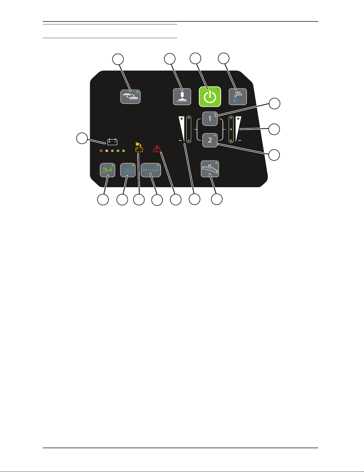
CONTROL PANEL COMPONENTS
PRO-MEMBRANE CONTROL PANEL MODEL
1
14
10
1. Brush change button
2. Brush pressure button
3. 1-Step button
4. Solution fl ow button
5. Preset zone control buttons
6. Solution fl ow indicator
7. Vacuum fan button
8. Brush pressure indicator
9. Service indicator
10. ec-H2O Button (option)
11. Automatic battery watering indicator
(option)
12. Severe Environment button (option)
13. Quiet-mode button (option)
14. Battery discharge / fault code indicator
2
9111213
3 4
5
6
5
78
12
T350 9016417 (02-2021)

PRO-PANEL CONTROL MODEL
OPERATION
18
19
1
10
2 3 4
9
1617
15
5
7
8
11
12
6
1314
1. Help button
2. Battery discharge indicator (BDI)
3. Severe Environment button (option)
4. ec-H2O button / indicator (option)
5. Service indicator / button
6. Solution fl ow button
7. Quiet mode button (option)
8. 1-Step button
9. Vacuum fan button
10. Brush pressure button
11. Solution fl ow increase button
12. Solution fl ow indicator
13. Solution fl ow decrease button
14. Brush change button
15. Preset zone control buttons
16. Video tutorial button
17. Brush pressure decrease button
18. Brush pressure indicator
19. Brush increase button
T350 9016417 (02-2021)
13
OPERATION
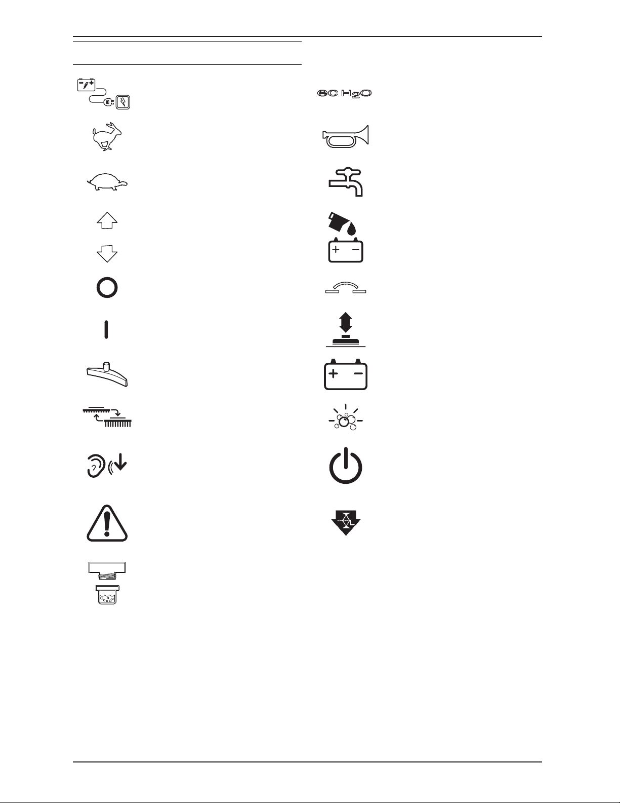
MACHINE SYMBOLS.
Battery charger ec-H2O scrubbing (option)
Fast scrub speed Horn
Slow scrub speed Solution fl ow
Direction (forward / reverse)
Key Off Circuit breaker
Key On Brush pressure
Vacuum fan Battery charge
Change brush Severe Environment (option)
Quiet mode (option) 1-Step
Service indicator Jack point
Automatic battery watering
(option)
14
Filter location
T350 9016417 (02-2021)
PRO-PANEL SYMBOLS
Home screen Machine Settings Factory reset
Back arrow Operator videos Operator
Login Supervisor menu Supervisor
Control help Video help Add profi le
Start-up video Add / Edit profi les Edit profi le
About Battery selection Copy profi le
Video list button Enable login Delete profi le
OPERATION
Video button Disable login User login
Video rotate view Calibrate touch Enter
Backspace
T350 9016417 (02-2021)
15
OPERATION
INSTALLING BATTERIES
WARNING: Batteries emit hydrogen
gas. Explosion or fi re can result. Keep
sparks and open fl ame away when
charging.
FOR SAFETY: When servicing machine, wear
appropriate personal protection equipment as
needed. Avoid contact with battery acid.
BATTERY SPECIFICATIONS
Requires four 6 volt deep-cycle batteries,
≤ 240 Ah @ 20 hr.
Contact distributor or Tennant for battery
recommendations.
FOR SAFETY: Before leaving or servicing
machine, stop on level surface, turn off
machine, and remove key.
1. Lift the recovery tank to access the battery
compartment.
3. Using the supplied battery post boots, connect
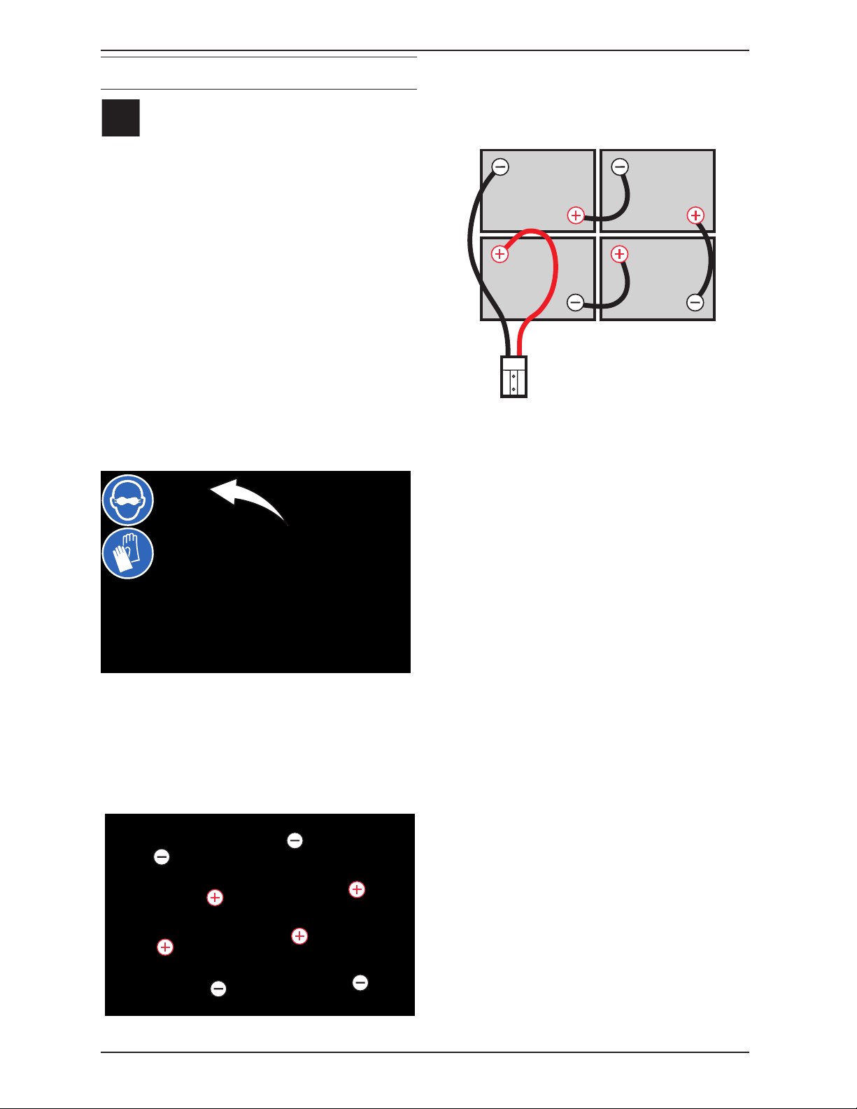
the cables to battery posts, RED TO POSITIVE
(+) & BLACK TO NEGATIVE (-). Tighten
cable connections to batteries per battery
manufacturer specifi cations.
BLACK
RED
IMPORTANT: Before charging batteries, make
sure the battery charger and the machine’s
battery discharge indicator are properly set for
battery type. Failure to properly set will result
in battery damage. See BATTERY CHARGER
SETTINGS.
2. Carefully install the batteries into the battery
compartment tray and arrange the battery
posts as shown.
FOR SAFETY: When servicing machine, use
a hoist or adequate assistance when lifting
batteries.
ATTENTION: Do not disconnect battery cables
while charger is plugged in, circuit board
damage may result.
ATTENTION: Batteries serve as a counterweight. Always maintain the minimum
counterweight to ensure machine stability and
traction.
IRIS Battery Charging Metrics Notifi cation:
Machines equipped with capability to report
battery charging data via IRIS are supplied with
a charger and set of batteries from the factory.
When a battery reaches its end of life and must
be replaced, Tennant highly recommends that
the same battery type be used to continue to
maximize the machines performance. In the event
a battery with a different amp hour (AH), type
(Flooded, AGM, Gel), or manufacturer is selected
for replacement please contact Tennant technical
service department for assistance in determining
the feasibility of the replacement batteries and
if so, selecting the correct charging profi le.
Availability of IRIS battery metric reporting is not
guaranteed with third party supplied batteries.
16
NOTE: If there is liquid in battery compartment,
drain battery compartment before installing
batteries. See BATTERY COMPARTMENT DRAIN
VALVE.
T350 9016417 (02-2021)

OPERATION
HOW THE MACHINE WORKS
Conventional scrubbing:
When using the conventional scrubbing mode,
water and detergent mixture from the solution tank
fl ows to the fl oor and the rotating brush(es)/pad(s)
scrub the fl oor clean. As the machine moves
forward, the squeegee with vacuum suction picks
up the dirty solution from the fl oor into the recovery
tank.
ec-H2O NanoClean Technology (option):
When using the ec-H2O NanoClean technology,
normal water passes through a module where it
is electrically converted into a cleaning solution.
The electrically converted water attacks the dirt,
allowing the machine to easily scrub away the
suspended soil. The converted water then returns
to normal water in the recovery tank.
BRUSH AND PAD INFORMATION
For best results, use the appropriate brush or
pad for the cleaning application. Listed below are
brushes and pads and the applications for which
each is best suited.
Stripping pad (Brown) - For stripping of fl oor
fi nish to prepare the fl oor for recoating.
Polypropylene Side Brush − For general
sweeping of light to medium debris.
Heavy duty stripping pad (Black) - Used for
aggressive stripping of heavy fi nishes/sealers, or
very heavy duty scrubbing.
Surface preparation pad (Maroon) - Used for
very aggressive chemical free removal of fl oor
fi nish to prepare the fl oor for re-coating.
Tufted pad driver - Standard pad driver has short
bristles, or “tufts,” on the back to hold the pad in
place. This driver works with all Tennant pads
except the black high productivity pad.
NOTE: The amount and type of soilage play an
important role in determining the type of brush or
pad to use. Contact a Tennant representative for
specifi c recommendations.
Soft nylon bristle scrub brush (White) -
Recommended for cleaning coated fl oors without
removing fi nish. Cleans without scuffi ng.
Polypropylene bristle scrub brush (Black) - This
general purpose polypropylene bristle scrub brush
is used for scrubbing lightly compacted soilage.
This brush works well for maintaining concrete,
wood and grouted tile fl oors.
Super abrasive bristle scrub brush (Gray) -
Nylon fi ber impregnated with abrasive grit to
remove stains and soilage. Strong action on any
surface. Performs well on buildup, grease, or tire
marks.
Polishing pad (White) - For maintaining highly
polished or burnished fl oors.
Buffi ng pad (Red) - For light duty scrubbing
without removing fl oor fi nish.
Scrubbing pad (Blue) − For medium to heavy
duty scrubbing. Removes dirt, spills, and scuffs.
T350 9016417 (02-2021)
17

OPERATION
MACHINE SETUP
ATTACHING SQUEEGEE ASSEMBLY
1. Lower the scrub head.
FOR SAFETY: Before leaving or servicing
machine, stop on level surface, turn off
machine, and remove key.
2. Rotate the squeegee carriage assembly to
the right side of the machine to access the
squeegee carriage.
5. Machines with 20 in. (500 mm) scrub
heads only: Be sure both squeegee tabs are
positioned above the scrub head skirt.
6. Connect the vacuum hose to the squeegee
assembly.
3. Align the squeegee carriage pins into the
squeegee assembly bracket.
4. Slide the squeegee assembly onto the
squeegee carriage until both squeegee
carriage pins are secured in the bracket.
7. Rotate and center the squeegee assembly
underneath the machine.
18
T350 9016417 (02-2021)

OPERATION
INSTALLING BRUSHES / PADS
1. Stand with both feet on the operator platform
(do not press the green go pedal), turn the
key to the ON position, and press the brush
change button to raise the scrub head to the
correct level for installing the pad(s).
Machines with Pro-Membrane controls:
Wait for the green LED light to stop fl ashing
and remain illuminated. See REPLACING
BRUSH(ES) PAD(S) ON PRO-MEMBRANE
MACHINES.
Machines with Pro-Panel controls: Follow
prompts on screen and wait for green
check mark to appear in the display. See
REPLACING BRUSH(ES) PAD(S) ON PROPANEL MACHINES.
WARNING: Magnetic Field Hazard.
Magnetic pad driver/brush can be
harmful to those with pacemakers or
medical implants.
Machines with 3-lug brush hubs: Position
the three lugs into the motor hub slots and
give the pad driver / brush a quick counterclockwise turn to engage hub.
FOR SAFETY: Before leaving or servicing
machine, stop on level surface, turn off
machine, and remove key.
2. Attach the pad to the pad driver before
installing the driver. Secure pad with centerlock.
3. Machines with magnetic brushes or pad
drivers: Position the brush under the scrub
head and lift the brush up onto the scrub head
until the magnet in the scrub head secures the
brush.
Replace pads or brushes when they no longer
clean effectively.
4. To remove the pad driver(s) / brush(es), repeat
Step 1, and then remove the brushes from
under the scrub head.
T350 9016417 (02-2021)
19

OPERATION
FILLING SOLUTION TANK
FOR SAFETY: Before leaving or servicing
machine, stop on level surface, turn off
machine, and remove key.
1. Remove the cap from the solution tank.
2. Insert the fi ll hose into the yellow strainer and
ensure the hose is held securely into place in
the strainer.
3. Fill the solution tank with water until level
reaches the 53 L (14 G) mark on the solution
tank indicator.
ec-H2O Scrubbing (Option)- Fill solution
tank with only cool clean water (less than
70°F/21°C). Do not add conventional fl oor
cleaning detergents. An ec-H2O system fault
will occur if cleaning detergents are added.
Conventional Scrubbing - Fill solution tank
with water (not to exceed 60°C/140°F). Pour
a recommended cleaning detergent into the
solution tank according to mixing instructions
on the container.
ATTENTION: For Conventional Scrubbing, only
use commercially approved cleaning detergents.
Machine damage due to improper detergent usage
will void the manufacturer’s warranty.
WARNING: Flammable materials can
cause an explosion or fi re. Do not use
fl ammable materials in tank(s).
NOTE: Do not use the ec-H2O system when
there are conventional cleaning detergents in the
solution tank. Drain, rinse, and refi ll the solution
tank with clean cool water before operating the ecH2O system. Conventional cleaning detergents will
cause an ec-H2O system fault.
4. Turn off the water supply and remove the fi ll
hose from the yellow strainer.
5. Replace the cap on the solution tank.
20
T350 9016417 (02-2021)

OPERATION
FILLING SEVERE ENVIRONMENT DETERGENT
TANK (ec-H2O MODEL OPTION)
FOR SAFETY: Before leaving or servicing
machine, stop on level surface, turn off
machine, and remove key.
1. Pull the access panel open to access the
Severe Environment tank.
2. Remove the Severe Environment tank from the
machine and set it on the fl oor.
3. Remove black cap from Severe Environment
tank and add a recommended cleaning
detergent at full concentration. Do not add
water.
WARNING: Flammable materials can
cause an explosion or fi re. Do not use
fl ammable materials in tank(s).
ATTENTION: Only use commercially approved
cleaning detergents in the Severe Environment
tank. Do not use cleaners based with d-limonene.
Machine damage due to improper detergent usage
will void the manufacturer’s warranty.
NOTE: Remove the Severe Environment tank from
the machine before fi lling the tank with detergent
to prevent damaging electronic components.
NOTE: To prevent from running out of detergent
while operating, it is recommended to refi ll the
Severe Environment tank when refi lling the
solution tank.
4. Replace cap on the Severe Environment tank.
5. Adjust the detergent mixing ratio knob
according to the cleaning detergent’s mixing
instructions.
T350 9016417 (02-2021)
21
OPERATION
ec-H2O WATER CONDITIONING CARTRIDGE
(ec-H2O MODEL)
FOR SAFETY: Before leaving or servicing
machine, stop on level surface, turn off
machine, and remove key.
The ec-H2O system is equipped with a water
conditioning cartridge. The cartridge is designed
to protect the machine’s plumbing system from
potential scaling.
The cartridge is required to be replaced when it
reaches its maximum water usage or expiration
time on when the cartridge was activated, which
ever comes fi rst.
Depending on machine usage a new cartridge can
last anywhere from 12 to 24 months.
All cartridges are labeled with a manufacture date.
The shelf-life of an un-installed cartridge is one
year from manufacture date. For new cartridge
replacement, the ec-H2O module timer must be
reset. See ec-H2O WATER CONDITIONING
CARTRIDGE REPLACEMENT.
Pro-Panel Models
ATTENTION: During fi rst time use and after
replacing the water conditioning cartridge, the
ec-H2O system will automatically override the
selected solution fl ow rate for up to 75 minutes.
The control panel will signal the following code
when it’s time to replace the cartridge. The ec-H2O
icon will begin to blink blue and red. See SERVICE
INDICATOR CODES for further details.
Pro-Membrane Models
22
T350 9016417 (02-2021)
OPERATION
FILLING AUTOMATIC BATTERY WATERING
TANK (OPTION)
FOR SAFETY: Before leaving or servicing
machine, stop on level surface, turn off
machine, and remove key.
1. Lift the recovery tank to access the automatic
battery watering tank. Drain recovery tank
before lifting tank.
2. Reposition the automatic battery watering tank
so that it can be easily fi lled.
4. Pour distilled water into tank. To avoid getting
water on sensitive components, use a funnel to
fi ll automatic battery watering tank.
FOR SAFETY: When using machine, only
use distilled water when fi lling the automatic
battery watering tank.
5. When the tank needs refi lling, the automatic
battery watering indicator will alert user to
add distilled water. See CONTROL PANEL
OPERATION for further details.
Pro-Membrane Model
3. Remove the blue cap from the automatic
battery watering tank.
T350 9016417 (02-2021)
Pro-Panel Model
6. Replace blue cap on automatic battery
watering tank and return the automatic battery
watering tank to the upright stowed position.
23
OPERATION
CONTROL PANEL OPERATION
The control panel operation can be set up with
lockout functionality by using the Supervisor
Controls feature. This will prevent the operator
from changing or saving the settings. See
SUPERVISOR CONTROLS instructions at the
back of the manual.
The supervisor controls feature will lower machine
variability for consistent, repeatable cleaning
results, provide machine quality assurance
regardless of user experience, and reduce user
training requirements.
OPERATION OF CONTROLS PRO-MEMBRANE CONTROLS
1-STEP BUTTON
With key turned on, press the 1-Step button to
activate the scrub function. The scrub head and
squeegee will lower to fl oor. Press button again
to stop the scrub function and to raise scrub head
and squeegee.
SOLUTION FLOW BUTTON
Press the solution fl ow button to increase or
decrease the solution fl ow rate. The solution fl ow
indicator will display fl ow setting. No LED = No
fl ow, One LED = Low fl ow, two LED’s = Medium
fl ow, three LED’s = High fl ow.
QUIET-MODE BUTTON (OPTION)
Press the Quiet-Mode button to reduce the
vacuum motor sound. The LED will illuminate
when activated. Press button again to turn off.
BRUSH PRESSURE BUTTON
Press the brush pressure button to increase or
decrease the brush pressure. The brush pressure
indicator will display the pressure setting. One LED
= Low pressure and two LED’s = High pressure.
24
T350 9016417 (02-2021)

OPERATION
SEVERE ENVIRONMENT BUTTON
(ec-H2O MODEL OPTION)
NOTE: When the Severe Environment mode is
turned on, the ec-H2O system will automatically
turn off and the brush pressure and solution
fl ow settings will increase to the high settings.
When turned off, the settings will revert back
to the original settings. When operating the
Severe Environment mode for extended periods,
if desired, the solution fl ow rate and the down
pressure can be decreased to a lower setting
to conserve solution and detergent usage and
optimize battery run time.
Press the Severe Environment button to deliver
a boost of cleaning detergent for areas with
excessive soil buildup.
Press button one time for a 30 second boost. A
green LED in the corner will blink slowly when
dispensing. During the last 5 seconds, the LED
will blink rapidly as an alert that the dispensing is
about to stop.
To deliver a continuous detergent boost, press and
hold button for 3 seconds until green LED turns
solid green. Press button at anytime to turn off.
PRESET ZONE CONTROL BUTTONS
Note: Zone 3 is only available on machines built
before serial number 11003113.
Use the zone control buttons to preset up to three
zones with different solution fl ow rates, brush
pressures, scrub speeds and scrub modes.
Zone 1 = Preset Zone Control Button 1
Zone 2 = Preset Zone Control Button 2
Zone 3 = Preset Zone Control Buttons 1 & 2
The zone control buttons are factory preset for
different scrubbing applications. To use Zone
3, press zone buttons 1 & 2 at the same time.
A green LED in the corner will turn on when
activated.
To alert user when Severe Environment tank is
empty, the bubbles icon will blink for 15 seconds. If
button is pressed when tank is empty, the bubbles
icon will continue to blink for 15 seconds until tank
is refi lled.
To preset the zone control buttons for different
scrubbing applications, select the desired settings
from list below, then press and hold the zone
button until the green LED blinks three times to
save preset. To preset zone 3, press and hold
zone buttons 1 & 2 at the same time.
- Brush pressure setting
- Solution fl ow rate
- Quiet-Mode on or off
- ec-H2O system on or off (option)
- Severe Environment mode on or off (option)
- Maximum scrub speed (see Supervisor
Controls)
NOTE: The Severe Environment mode and
ec-H2O system cannot be preset together.
T350 9016417 (02-2021)
25
OPERATION
ec-H2O BUTTON / INDICATOR (OPTION)
The ec-H2O system automatically turns on at each
key start. A blue ec-H2O indicator appears when
machine is equipped with the ec-H2O option. The
green LED illuminates when ec-H2O is activated.
To turn off the ec-H2O system, press the ec-H2O
button. The green LED indicator will disappear.
ec-H2O INDICATOR CONDITION
Solid green Normal operation
Blinking blue/red Water conditioning
cartridge expired.
Replace cartridge.
Solid or blinking red A system fault has
occurred. See Service
Indicator Codes.
NOTE: If a fault occurs to the ec-H2O system,
the machine may automatically turn off the ecH2O system and convert over to conventional
scrubbing. The service indicator icon will remain
solid red or continue to blink red until the ec-H2O
fault is serviced.
BATTERY DISCHARGE INDICATOR
The battery discharge indicator (BDI) displays the
charge level of the batteries while the machine is
operating. When the batteries are fully charged,
all fi ve indicators are lit. When the discharge level
reaches the red light, stop scrubbing and recharge
the batteries. When the red light begins to fl ash,
the scrub function will be disabled to protect the
batteries from total discharge. The machine will
still propel when the red light is fl ashing. This will
allow user to transport the machine to the charging
station.
AUTOMATIC BATTERY WATERING INDICATOR
(OPTION)
The automatic battery watering indicator will fl ash
when the battery watering tank is empty and needs
refi lling. To protect the batteries from damage, the
machine’s scrub function will be disabled after 10
hours of additional use if tank is not refi lled. When
the indicator fl ashes rapidly, the scrub function
will be disabled. Add distilled water and restart
key to clear the fl ashing indicator. See FILLING
AUTOMATIC BATTERY WATERING TANK.
SERVICE INDICATOR
When the machine or on-board battery charger
detects a fault, the service indicator will light up
and begin fl ashing. The battery discharge indicator
lights will also fl ash a fault code. See SERVICE
INDICATOR CODES to diagnose machine fault.
26
T350 9016417 (02-2021)
 Loading...