

Tennant 8200 User Manual
8200
Home
Find...
Go To..
Operator Manual
www.tennantco.com
330060
Rev. 08 (3-2006)
*330060*
This manual is furnished with each new model. It provides
Home
Find...
Go To..
necessary operation and maintenance instructions.
Read this manual completely and understand the machine before operating or servicing it.
MACHINE DATA
This machine will provide excellent service. However, the
best results will be obtained at minimum costs if:
S The machine is operated with reasonable care.
S The machine is maintained regularly - per the ma-
chine maintenance instructions provided.
S The machine is maintained with manufacturer sup-
plied or equivalent parts.
PROTECT THE ENVIRONMENT
Please dispose of packaging materials,
old machine components such as
batteries, hazardous fluids such as
antifreeze and oil, in a safe
environmentally way according to your
local waste disposal regulations.
Always remember to recycle.
Please fill out at time of installation for future reference.
Model No.- 8200
Serial No.-
Machine Options --
Sales Rep. --
Sales Rep. phone no. --
Customer Number --
Installation Date --
Tennant Company
PO Box 1452
Minneapolis, MN 55440
Phone: (800) 553--8033 or (763) 523--2850
CALIFORNIA PROPOSITION 65 WARNING:
Engine exhaust from this product contains chemicals known to the State of California to cause cancer,
birth defects, or other reproductive harm.
MAXPRO and ES are United States registered trademarks of the Tennant Company
Thermo Sentry is a United States trademark of Tennant Company.
Specifications and parts are subject to change without notice.
Copyright E 1998-- 2000, 2002--2006 TENNANT, Printed in U.S.A.

CONTENTS
Home
Find...
Go To..
CONTENTS
Page
SAFETY PRECAUTIONS 3...................
OPERATION 7..............................
OPERATOR RESPONSIBILITY 7...........
MACHINE COMPONENTS 8...............
SYMBOL DEFINITIONS 9..................
CONTROLS AND INSTRUMENTS 1 1.....
OPERATION OF CONTROLS 12.........
DIRECTIONAL PEDAL 12.............
BRAKE PEDAL 13...................
PARKING BRAKE PEDAL 13..........
IGNITION SWITCH 14................
STEERING WHEEL 14...............
STEERING COLUMN TILT LEVER
(OPTION) 14.....................
CHECK ENGINE LIGHT (GM ENGINE) 15
MAIN SWEEP BRUSH LEVER 15......
MAIN SWEEP BRUSH DOWN
PRESSURE KNOB 15.............
SIDE BRUSH LEVER 16..............
SIDE BRUSH DOWN PRESSURE
HANDLE 16......................
HOPPER LEVER 16..................
HOPPER DOOR LEVER 17...........
CONTROL PANEL 17.................
HOURMETER 17....................
FUEL LEVEL GAUGE 17..............
SCRUB SWITCH 18..................
SQUEEGEE SWITCH 19..............
EDGE SCRUB SWITCH (OPTION) 19..
ES SWITCH (OPTION) 20.............
RECOVERY TANK FULL INDICAT OR 20
DETERGENT PUMP SWITCH
(OPTION) 21.....................
ENGINE SPEED SWITCH 21..........
SWEEPING VACUUM FAN SWITCH 22
FILTER SHAKER SWITCH 22.........
OPERATING LIGHTS SWITCH 23.....
OPERATING/HAZARD LIGHT
SWITCH (OPTION) 23.............
SOLUTION FLOW SWITCH 23........
MANUAL FLOW VALVE 24............
ENGINE CHOKE KNOB
(FORD ENGINE) 24...............
CHARGING SYSTEM LIGHT 25.......
ENGINE OIL PRESSURE LIGHT 25....
ENGINE WATER TEMPERATURE
LIGHT 25.........................
HOPPER TEMPERATURE LIGHT --
THERMO SENTRY 26.............
OK LIGHT 26........................
CLOGGED FILTER LIGHT (OPTION) 26
HOPPER DOOR CLOSED LIGHT
(OPTION) 27.....................
HYDRAULIC FILTER BYPASS LIGHT
(OPTION) 27.....................
HORN BUTTON 27...................
Page
CIRCUIT BREAKERS 28..............
FUSES (GM ENGINE) 28
OPERATOR SEAT 29.................
ADJUSTABLE SEAT (OPTION) 29.......
DELUXE SUSPENSION SEAT
(OPTION) 29.......................
HOPPER SUPPORT BAR 31............
ENGINE COVER GAS SPRING 31.......
LATCHES 31..........................
HOW THE MACHINE WORKS 32...........
PRE-OPERATION CHECKLIST 33..........
CHANGING AN LPG FUEL TANK 34........
STARTING THE MACHINE 36..............
SWEEPING, SCRUBBING, AND
BRUSH INFORMATION 38..............
SWEEPING 40...........................
STOP SWEEPING 41.....................
EMPTYING THE HOPPER 42..............
FILLING THE TANKS 44...................
SCRUBBING 46..........................
DOUBLE SCRUBBING 48..................
STOP SCRUBBING 48....................
DRAINING AND CLEANING THE TANKS 49.
STOP THE MACHINE 52..................
POST-OPERATION CHECKLIST 54.........
ENGAGING HOPPER SUPPORT BAR 55...
DISENGAGING HOPPER
SUPPORT BAR 57.....................
OPERATION ON INCLINES 58.............
TIE DOWNS 58...........................
MACHINE TROUBLESHOOTING 59........
MAINTENANCE 62..........................
MAINTENANCE CHART 62................
LUBRICATION 64.........................
ENGINE (FORD) 64....................
ENGINE (GM) 64......................
REAR WHEEL SUPPORT 65............
FRONT WHEEL BEARINGS 66..........
HOPPER LIFT ARM PIVOTS 66.........
SCRUB HEAD DRAG LINK ARMS 66.....
HYDRAULICS 67.........................
HYDRAULIC FLUID RESERVOIR 67.....
HYDRAULIC FLUID 68.................
HYDRAULIC HOSES 69................
PROPELLING MOTOR 69...............
ENGINE 70..............................
COOLING SYSTEM 70.................
AIR FILTER INDICATOR (OPTIONAL) 71.
AIR FILTER 71.........................
FUEL FILTER (GASOLINE) 72...........
FUEL FILTER (GM LPG) 72.............
SPARK PLUGS 72.....................
CRANKCASE VENTILATION SYSTEM 72.
INTAKE MANIFOLD (FORD) 72
TIMING BELT (GM) 72..................
BATTERY 73.............................
.............
..........
8200 330060 (3-- 06)
1

CONTENTS
Home
Find...
Go To..
Page
BELTS AND CHAINS 74...................
ENGINE AND ACCESSORY
PUMP BELT (FORD) 74..............
ENGINE BELT (GM) 74.................
STATIC DRAG CHAIN 75...............
DEBRIS HOPPER 76......................
HOPPER DUST FILTER 76..............
REMOVING HOPPER DUST
FILTER 77.......................
THERMO SENTRY 77..................
SCRUB HEAD 78.........................
BRUSHES 78.............................
MAIN SWEEP BRUSH 78..................
REPLACING MAIN SWEEP BRUSH 79...
CHECKING AND ADJUSTING MAIN
SWEEP BRUSH PATTERN 81........
SIDE BRUSH 83..........................
REPLACING SIDE BRUSH 84...........
SCRUB BRUSHES 85.....................
REPLACING THE SCRUB BRUSHES 86.
SOLUTION SYSTEM 86...................
RECOVERY TANK 86..................
SOLUTION TANK 87...................
SQUEEGEES 87..........................
REAR SQUEEGEE 87..................
LEVELING THE REAR SQUEEGEE 88
ADJUSTING REAR SQUEEGEE
BLADE DEFLECTION 89..........
SIDE SQUEEGEES 90.................
ADJUSTING THE SIDE
SQUEEGEES 90.................
SQUEEGEE BLADES 90..................
REAR SQUEEGEE 90..................
REPLACING OR ROTATING REAR
SQUEEGEE BLADES 90..........
SIDE SQUEEGEES 91.................
REPLACING SIDE SQUEEGEE
BLADES 91......................
SKIRTS AND SEALS 92...................
REAR SKIRTS 92......................
BRUSH DOOR SEALS 92...............
HOPPER LIP SKIRTS 92................
HOPPER SEALS 93....................
HOPPER DOOR SEALS 93.............
HOPPER FILTER SEALS 93.............
HOPPER VACUUM FAN SEAL 94........
TANK COVER SEALS 94...............
BRAKES AND TIRES 95...................
SERVICE BRAKES 95..................
PARKING BRAKE 95...................
TIRES 95.............................
REAR WHEEL 95......................
PUSHING, TOWING, AND
TRANSPORTING THE MACHINE 96.....
PUSHING OR TOWING THE
MACHINE 96.......................
TRANSPORTING THE MACHINE 97.....
MACHINE JACKING 99....................
STORING MACHINE 99...................
Page
SPECIFICATIONS 100......................
GENERAL MACHINE PERFORMANCE 100.
POWER TYPE 101.......................
STEERING 101..........................
HYDRAULIC SYSTEM 102................
BRAKING SYSTEM 102..................
TIRES 102..............................
MACHINE DIMENSIONS 103..............
INDEX 104.................................
2
8200 330060 (3-- 06)

SAFETY PRECAUTIONS
Home
Find...
Go To..
SAFETY PRECAUTIONS
The following precautions are used throughout
this manual as indicated in their description:
WARNING: To warn of hazards or
unsafe practices that could result in
severe personal injury or death.
FOR SAFETY: To identify actions that
must be followed for safe operation of
equipment.
CAUTION: To warn of unsafe practices
that could result in minor or moderate
personal injury.
The machine is suited to sweep disposable
debris. Do not use the machine other than
described in this Operator Manual. The machine
is not designed for use on public roads.
The following information signals potentially
dangerous conditions to the operator or
equipment:
WARNING: Engine emits toxic gases.
Severe respiratory damage or
asphyxiation can result. Provide
adequate ventilation. Consult with your
regulatory authorities for exposure
limits. Keep engine properly tuned.
WARNING: Raised hopper may fall.
Engage hopper support bar.
WARNING: Lift arm pinch point. Stay
clear of hopper lift arms.
WARNING: Moving belt and fan. Keep
away.
WARNING: Flammable materials can
cause an explosion or fire. Do not use
flammable materials in tank(s).
WARNING: Flammable materials or
reactive metals can cause explosion or
fire. Do not pick up.
FOR SAFETY:
1. Do not operate machine:
-- Unless trained and authorized.
-- Unless operator manual is read and
understood.
-- If it is not in proper operating
condition.
-- In flammable or explosive areas unless
designed for use in those areas.
-- In areas with possible falling objects
unless equipped with overhead guard.
2. Before starting machine:
-- Check for fuel, oil, and liquid leaks.
-- Keep sparks and open flame away
from refuelin g area.
-- Make sure all safety devices are in
place and operate properly.
-- Check brakes and steering for proper
operation.
3. When starting machine:
-- Keep foot on brake and directional
pedal in neutral.
4. When using machine:
-- Use brakes to stop machine.
-- Go slow on inclines and slippery
surfaces.
-- Use care when reversing machine.
-- Move machine with care when hopper
is raised.
-- Make sure adequate clearance is
available before raising hopper.
-- Do not carry passengers on machine.
-- Always follow safety and traffic rules.
-- Report machine damage or faulty
operation immediately.
-- Follow mixing and handling
instructions on chemical containers.
5. Before leaving or servicing machine:
-- Stop on level surface.
-- Set parking brake.
-- Turn off machine and remove key.
WARNING: Hot bumper. Keep away.
CAUTION: LPG engine will run for a few
seconds after the key is turned off.
Apply the partking brake before leaving
the machine.
8200 330060 (9-- 05)
3

SAFETY PRECAUTIONS
Home
Find...
Go To..
6. When servicing machine:
-- Avoid moving parts. Do not wear loose
jackets, shirts, or sleeves.
-- Block machine tires before jacking
machine up.
-- Jack machine up at designated
locations only. Block machine up with
jack stands.
-- Use hoist or jack that will support the
weight of the machine.
-- Wear eye and ear protection when
using pressurized air or water.
-- Disconnect battery connections before
working on machine.
-- Avoid contact with battery acid.
-- Avoid contact with hot engine coolant.
-- Allow engine to cool.
-- Keep flames and sparks away from
fuel system service area. Keep area
well ventilated.
-- Use cardboard to locate leaking
hydraulic fluid under pressure.
-- Use Tennant supplied or approved
replacement parts.
7. When loading/unloading machine
onto/off truck or trailer:
-- Turn off machine.
-- Use truck or trailer that will support
the weight of the machine.
-- Use winch. Do not drive the machine
onto/off the truck or trailer unless the
load height is 380 mm (15 in) or less
from the ground.
-- Set parking brake after machine is
loaded.
-- Block machine tires.
-- Tie machine down to truck or trailer.
4
8200 330060 (6-- 03)
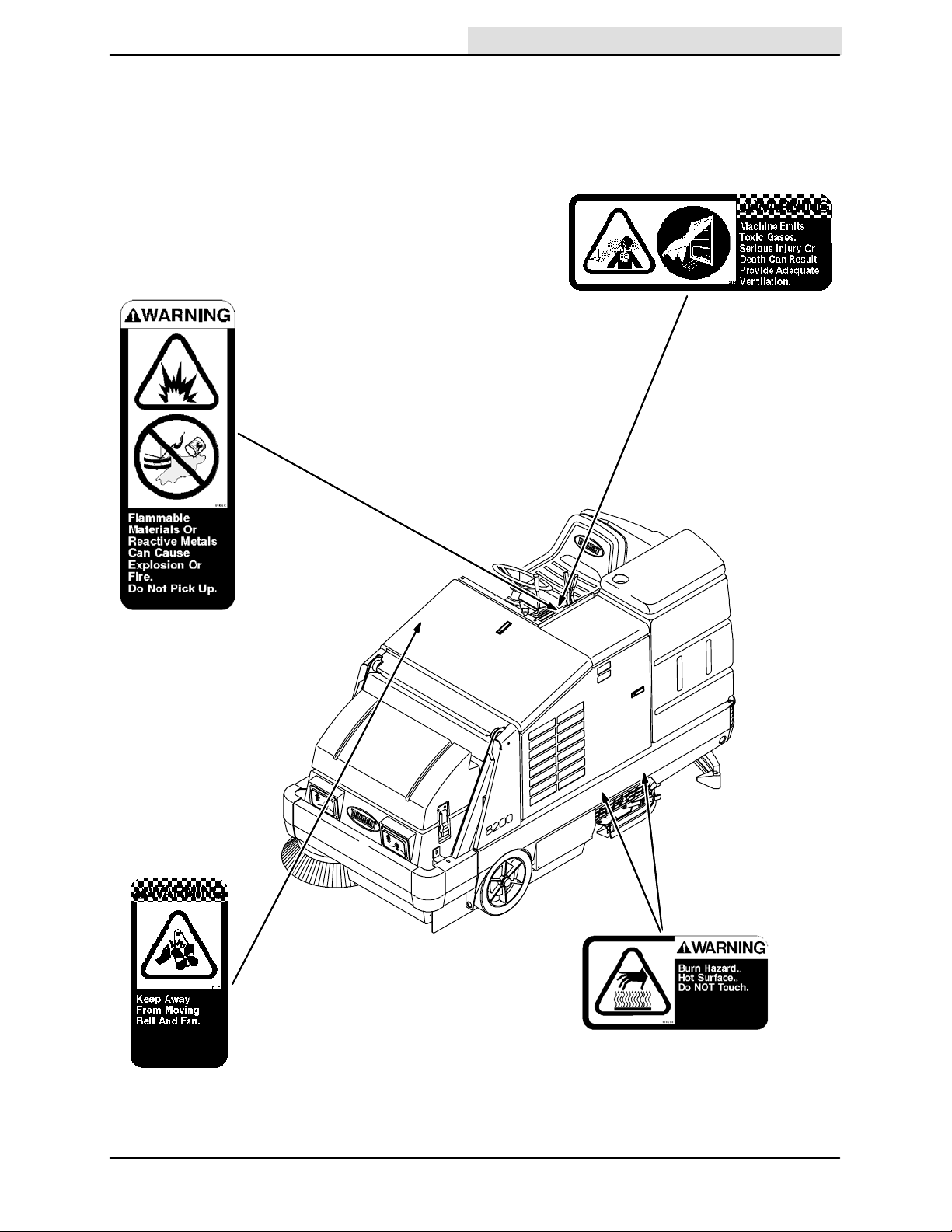
The following safety labels are mounted on the
Home
Find...
Go To..
machine in the locations indicated. If these or any
label becomes damaged or illegible, install a new
label in its place.
FLAMMABLE SPILLS LABEL -- LOCATED
ON THE SIDE PANEL OF THE OPERATOR
COMPARTMENT.
SAFETY PRECAUTIONS
EMISSIONS LABEL -- LOCATED ON THE SIDE
PANEL OF THE OPERATOR COMPARTMENT.
ENGINE FAN AND BELT LABEL -- LOCATED
ON THE RADIAT OR SHROUD.
8200 330060 (3-- 06)
HOT SURFACE LABEL -LOCATED ON THE SIDE OF
THE BUMPER
351550
5
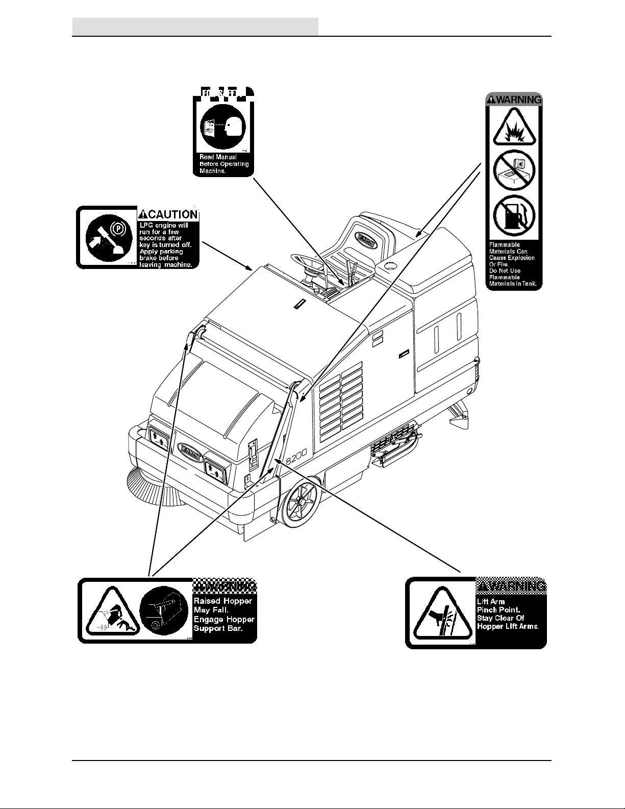
SAFETY PRECAUTIONS
Home
Find...
Go To..
LPG ENGINE WILL RUN LABEL-LOCATED ON THE SIDE OF THE
INSTRUMENT PANEL.
FLAMMABLE MATERIALS LABEL -- LOCATED
ON THE SOLUTION TANK COVER & ON THE
BA TTER Y TRA Y ON MACHINES WITH THE
DETERGENT TANK OPTION.
FOR SAFETY LABEL -LOCATED ON THE SIDE
PANEL OF THE OPERATOR
COMPARTMENT.
HOPPER SUPPORT BAR LABEL -- LOCATED
ON THE HOPPER SUPPORT BAR AND ON
BOTH HOPPER LIFT ARMS.
6
HOPPER LIFT ARMS LABEL -- LOCATED
ON BOTH HOPPER LIFT ARMS.
351550
8200 330060 (9-- 05)
OPERATOR RESPONSIBILITY
Home
Find...
Go To..
- The operator’s responsibility is to take care
of the daily maintenance and checkups of
the machine to keep it in good working
condition. The operator must inform the
service mechanic or supervisor when the
required maintenance intervals occur as
stated in the MAINTENANCE section of this
manual.
- Read this manual carefully before operating
this machine.
FOR SAFETY: Do not operate machine,
unless operation manual is read and
understood.
- Check the machine for shipping damage.
Check to make sure machine is complete
per shipping instructions.
OPERATION
OPERAT ION
- Keep your machine regularly maintained by
following the maintenance information in this
manual. We recommend taking advantage
of a regularly scheduled service contract
from your Tennant representative.
- Order parts and supplies directly from your
authorized Tennant representative. Use the
parts manual provided when ordering parts.
- After the first 50 hours of operation, follow
the recommended procedures stated in the
MAINTENANCE CHART.
07324
8200 330060 (1-- 98)
7
OPERATION
Home
Find...
Go To..
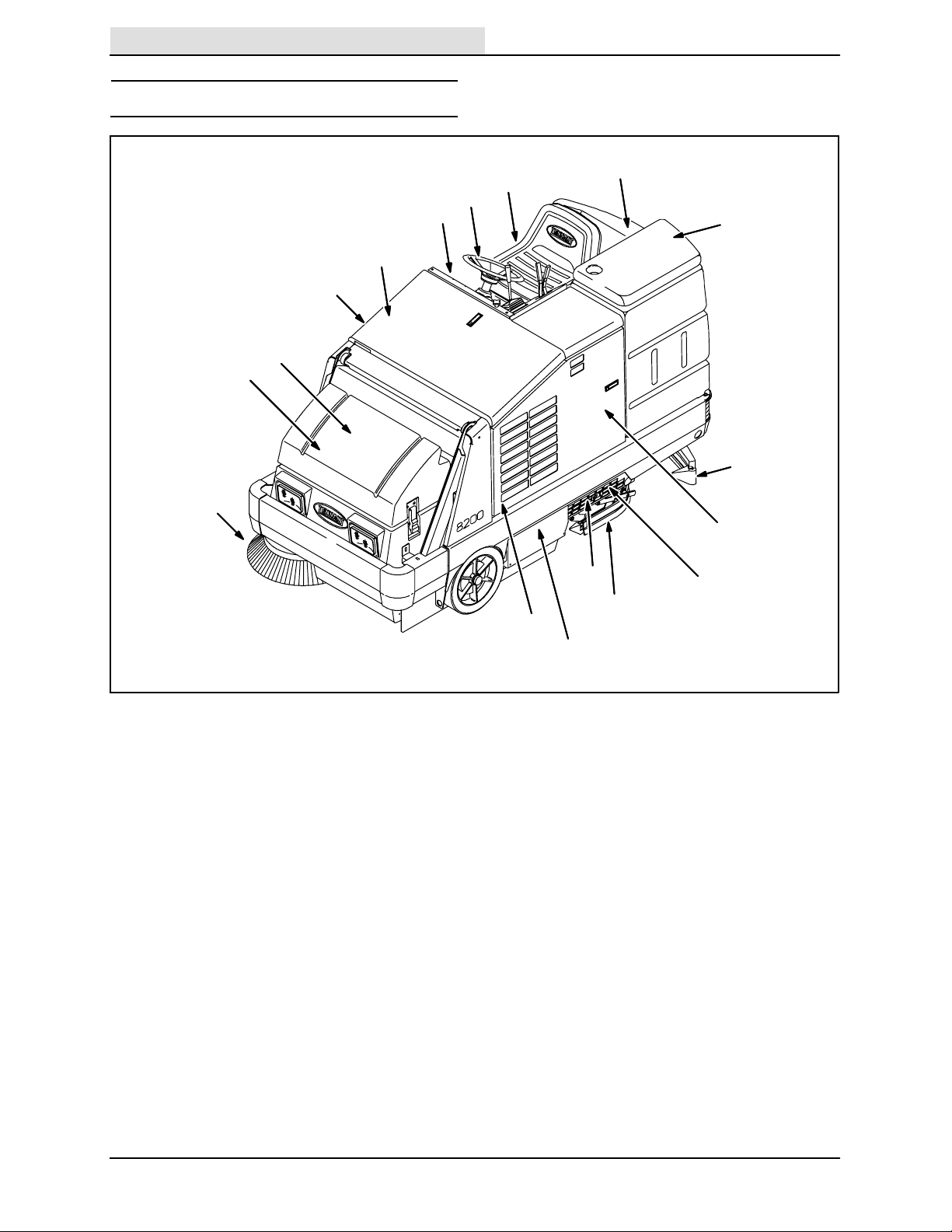
MACHINE COMPONENTS
C
B
A
D
H
I
J
N
P
K
L
F
E
Q
G
O
A. Control panel
B. Steering wheel
C. Operator seat
D. Engine cover
E. Engine side door
F. Rear squeegee
G. Side squeegee
H. Sweeping brush access door
I. Hopper cover
J. Hopper dust filter
K. Solution tank
L. Recovery tank
M. Main sweeping brush
N. Side brush
O. Scrub brushes
P. Detergent tank (option)
Q. Scrub head
M
351550
8
8200 330060 (6-- 04)
SYMBOL DEFINITIONS
Home
Find...
Go To..
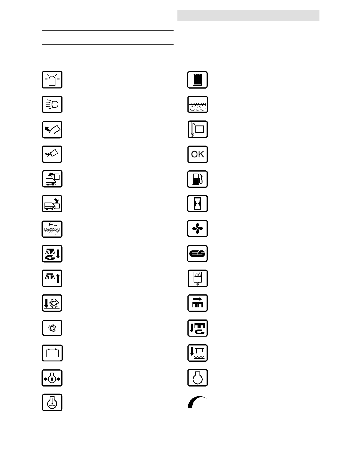
These symbols identify controls, displays, and
features on the machine:
Hazard light Recovery tank full
Operating lights Filter clogged
Hopper door open Hopper temperature -- Thermo Sentry
Hopper door close Diagnostics
Hopper raise Gasoline fuel only
OPERATION
Hopper lower Hourmeter
Filter shaker Fan
Side brush down and on ES (option)
Side brush up and off Detergent flow
Main brush down and on Scrub brush edge clean
Main brush up and off Scrub brushes down and on
Charging system Rear squeegee down and vacuum on
Engine oil pressure Engine
Engine water temperature Variable pressure
8200 330060 (6-- 04)
9
OPERATION
Home
Find...
Go To..
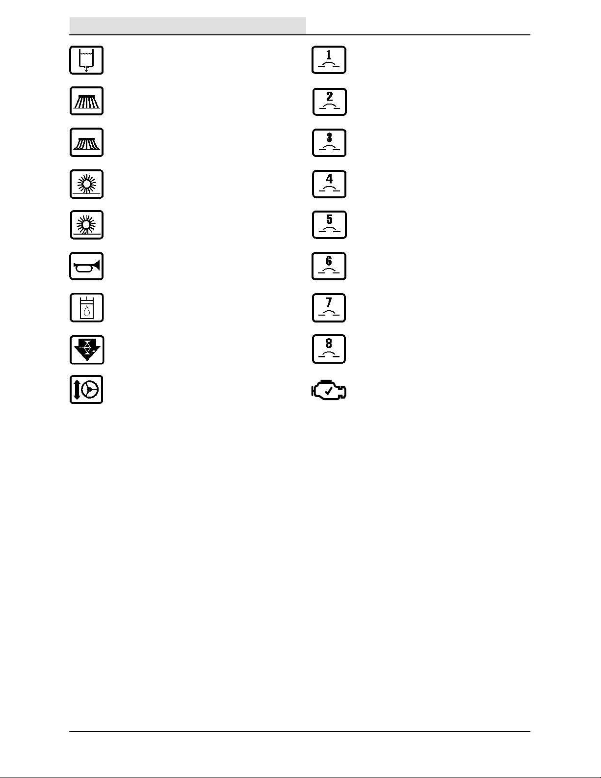
Solution flow Circuit breaker 1
Side brush down pressure light Circuit breaker 2
Side brush down pressure heavy Circuit breaker 3
Main sweep brush down pressure light Circuit breaker 4
Main sweep brush down pressure heavy Circuit breaker 5
Horn Circuit breaker 6
Hydraulic fluid only Circuit breaker 7
Jackpoint Circuit breaker 8
Steering tilt (option) Check Engine
10
8200 330060 (6-- 04)
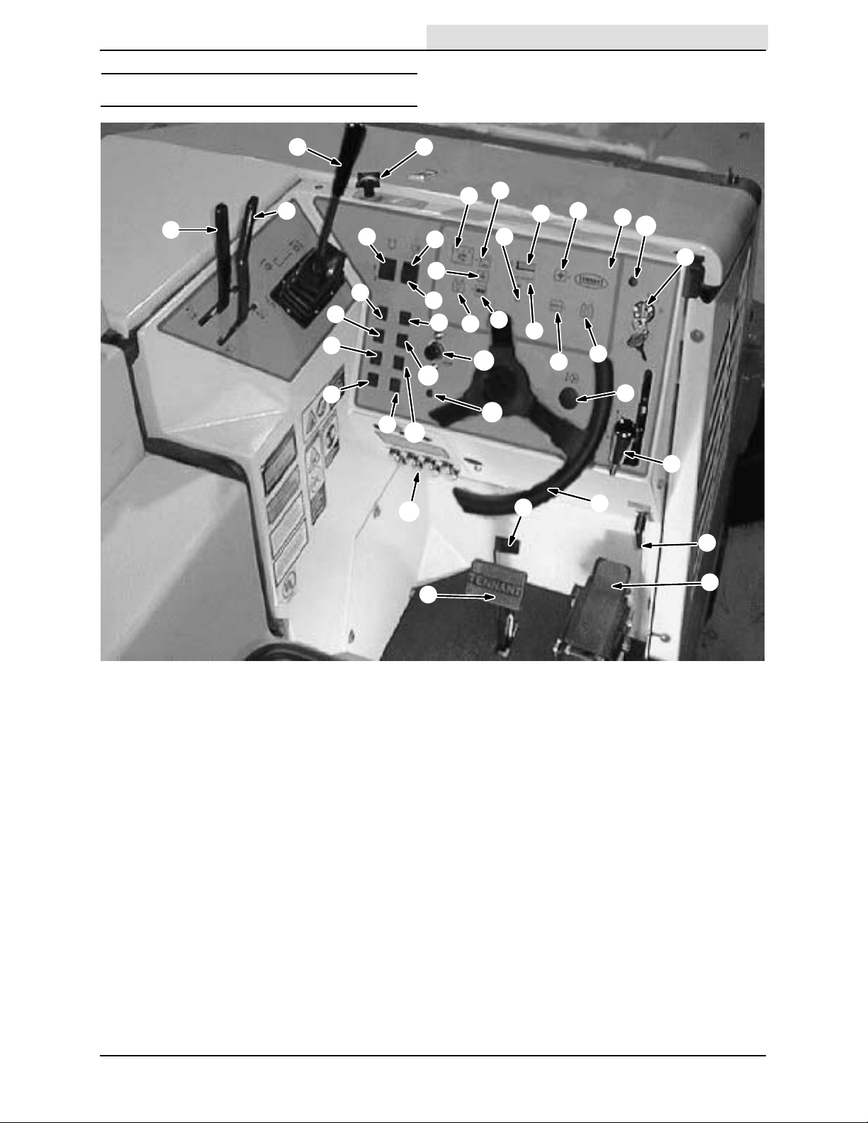
CONTROLS AND INSTRUMENTS
Home
Find...
Go To..
OPERATION
L
J
K
I
BB
CC
DD
EE
R
U
T
G
V
H
FF
GG
II
HH
KK
N
W
X
JJ
LL
Q
C
Z
P
AA
O
MM
D
Y
F
M
E
S
B
A
A. Directional pedal U. Squeegee switch
B. Brake pedal V. Edge scrub switch (option)
C. Parking brake pedal W. ES switch (option)
D. Ignition switch X. Detergent pump switch (option)
E. Steering wheel Y. Engine speed switch
F. Steering column tilt lever (option) Z. Sweeping vacuum fan switch
G. Operating lights switch AA. Filter shaker switch
H. Operating/hazard light switch BB. Charging system light
(option) CC. Engine oil pressure light
I. Solution flow switch DD. Engine water temperature light
J. Hopper door lever EE. Hopper temperature light -K. Hopper lever Thermo Sentry
L Main sweep brush lever FF. OK light
M. Side brush lever GG. Clogged filter light (option)
N. Recovery tank full indicator HH. Hopper door closed light (option)
O. Control panel II. Hydraulic filter bypass light (option)
P. Hourmeter JJ. Horn button
Q. Fuel level gauge KK. Circuit breakers
R. Main sweep brush down pressure LL. Engine choke knob (FORD engine)
S. Side brush down pressure handle MM. Check Engine Light (GM engine)
T. Scrub switch
8200 330060 (3-- 06)
11
OPERATION
Home
Find...
Go To..
OPERATION OF CONTROLS
DIRECTIONAL PEDAL
The directional pedal controls direction of travel
and the propelling speed of the machine. Change
the speed of the machine with the pressure of
your foot; the harder you press the pedal, the
faster the machine travels.
Forward: Press the top of the directional pedal
with the toe portion of your foot.
Reverse: Press the bottom of the directional
pedal with the heel of your foot.
Neutral: Take your foot off the directional pedal
and it will return to the neutral position.
12
8200 330060 (1-- 98)

BRAKE PEDAL
Home
Find...
Go To..
The brake pedal stops the machine.
Stop: Take your foot off the directional pedal and
let it return to the neutral position. Step on the
brake pedal.
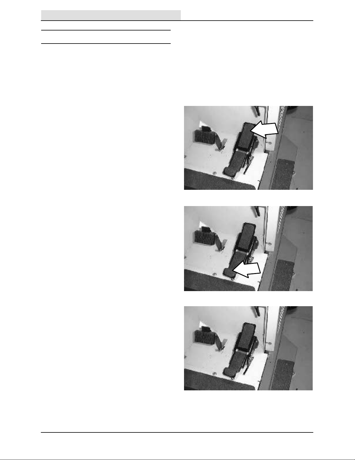
PARKING BRAKE PEDAL
The parking brake pedal sets and releases the
front wheel brakes.
Set: While pressing the brake pedal as far as it
will go, set the parking brake by pressing the
parking brake pedal with the toe portion of your
foot.
OPERATION
FOR SAFETY: Before leaving or
servicing machine; stop on level
surface, set parking brake, turn off
machine and remove key.
Release: Press on the brake pedal to unlock the
parking brake pedal.
8200 330060 (1-- 98)
13
OPERATION
Home
Find...
Go To..
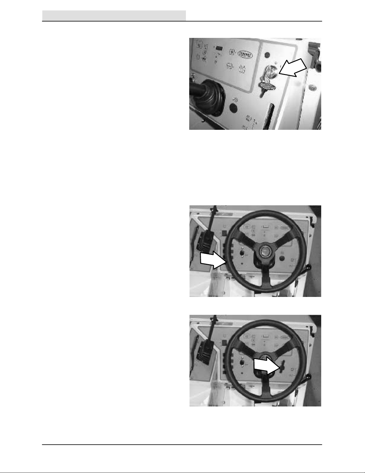
IGNITION SWITCH
The ignition switch starts and stops the engine
with a key.
FOR SAFETY: When starting machine,
keep foot on brake and directional pedal
in neutral.
Start: Turn the key all the way clockwise.
Release the key as soon as the engine starts.
Stop: Turn the key counter-clockwise.
CAUTION: LPG engine will run for a few
seconds after the key is turned off.
Apply the partking brake before leaving
the machine.
NOTE: T o protect the GM engines emmision
components on the LPG powered machines, the
engine will continue to operate for a few seconds
after the switch is turned off.
STEERING WHEEL
The steering wheel controls the machine’s
direction. The machine is very responsive to the
steering wheel movements.
Left: Turn the steering wheel to the left.
Right: Turn the steering wheel to the right.
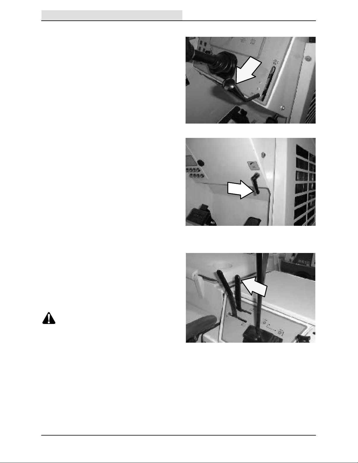
STEERING COLUMN TILT LEVER (O PTION)
The steering column tilt handle controls the angle
of the steering wheel.
Adjust: Pull out the tilt handle, then move the
wheel to the desired position and release the tilt
handle.
14
8200 330060 (9-- 05)
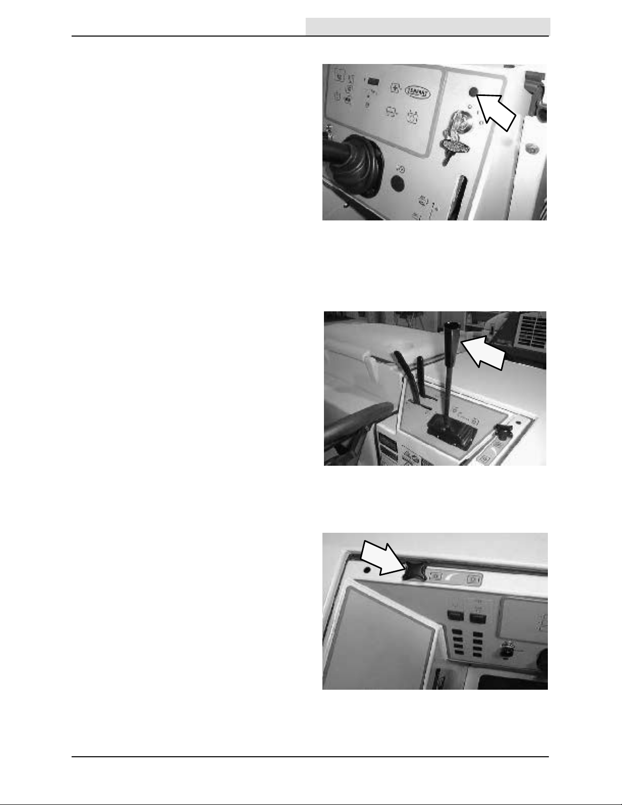
CHECK ENGINE LIGHT (GM ENGINE)
Home
Find...
Go To..
The check engine light comes on if the engines
control system detects a fault during machine
operation.
If the check engine light comes on while operating
the machine, contact a TENNANT service
representative.
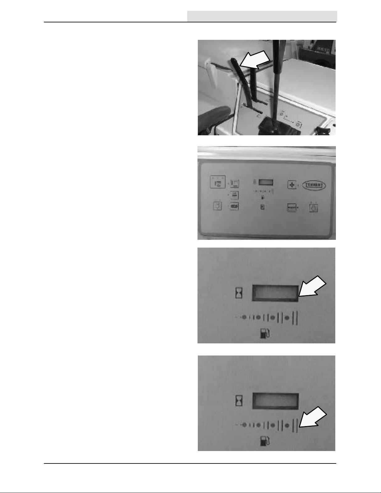
MAIN SWEEP BRUSH LEVER
The main sweep brush lever controls the position
and rotation of the main sweeping brush.
OPERATION
Main brush down and on: Pull the lever back and
to the right, then allow it to move forward into the
main brush down and on position.
Main brush up and off: Pull the lever back and to
the left into the main brush up and off position.
The brush will raise, stop rotating, and the
vacuum fan will shut off automatically.
NOTE: The filter shaker will automatically shake
the filter for 15 seconds each time the main brush
is raised.
MAIN SWEEP BRUSH DOWN PRESSURE
KNOB
The main brush down pressure knob changes the
amount of contact the main brush has with the
surface being swept.
Increase: Turn the main brush down pressure
knob counter--clockwise.
Decrease: Turn the main brush down pressure
knob clockwise.
8200 330060 (6-- 04)
15
OPERATION
Home
Find...
Go To..
SIDE BRUSH LEVER
The side brush lever controls the position and
rotation of the side brush.
Side brush down and on: Pull the lever back and
to the right, then allow it to move forward into the
side brush down and on position. The brush will
automatically start rotating.
Side brush up and off: Pull the lever back and to
the left into the side brush up and off position.
SIDE BRUSH DOWN PRESSURE HANDLE
The side brush down pressure handle changes
the amount of contact the side brush has with the
surface being swept.
Increase: Turn the side brush down pressure
handle counter-clockwise.
Decrease: Turn the side brush down pressure
handle clockwise.
HOPPER LEVER
The hopper lever raises and lowers the hopper.
Hopper up: Pull and hold the hopper lever
backward until the hopper reaches the desired
height.
Hold: Release the hopper lever into the middle
position.
WARNING: Raised hopper may fall.
Engage hopper support bar.
Hopper down: Push the hopper lever forward until
the hopper has lowered completely.
NOTE: The main sweeping brush, side brush, and
sweep vacuum fan will stop operating when the
hopper is raised. If the sweep vacuum fan, side
brush switch, or the main brush switch is pressed
while the hopper is raised, none of the sweeping
operations will activate.
16
8200 330060 (6-- 04)
HOPPER DOOR LEVER
Home
Find...
Go To..
The hopper door lever opens and closes the
hopper door.
Hopper door close: Pull and hold the hopper door
lever backward for approximately four seconds or
until the hopper door closed light (option) on the
dashboard illuminates.
Hopper door open: Push the hopper door lever
forward to the detent position.
CONTROL PANEL
The control panel controls all scrubbing
operations and the sweeping vacuum fan and
filter shaker motor.
OPERATION
HOURMETER
The hourmeter records the number of hours the
machine has been operated. Check the hourmeter
regularly; this information is used to determine
when to perform routine machine maintenance.
FUEL LEVEL GAUGE
The fuel level gauge indicates the amount of fuel
remaining in the fuel tank. As the fuel is
consumed, the indicator lights will move across
the display from right to left. When only the light
on the far left is lit, the fuel tank is nearly empty.
Refill the fuel tank as soon as possible.
LPG powered machine: The fuel gauge is located
on the top of the LP tank.
NOTE: Do not use leaded fuels. The use of
leaded fuels will cause permanent damage to the
system’s oxygen sensor and catalytic converter.
8200 330060 (6-- 04)
17

OPERATION
Home
Find...
Go To..
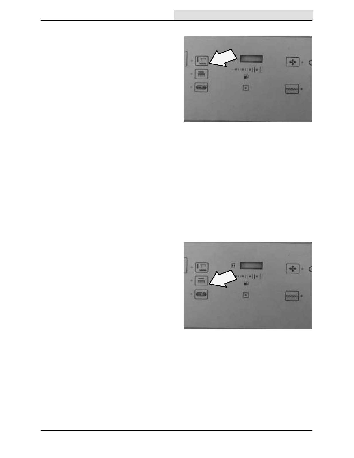
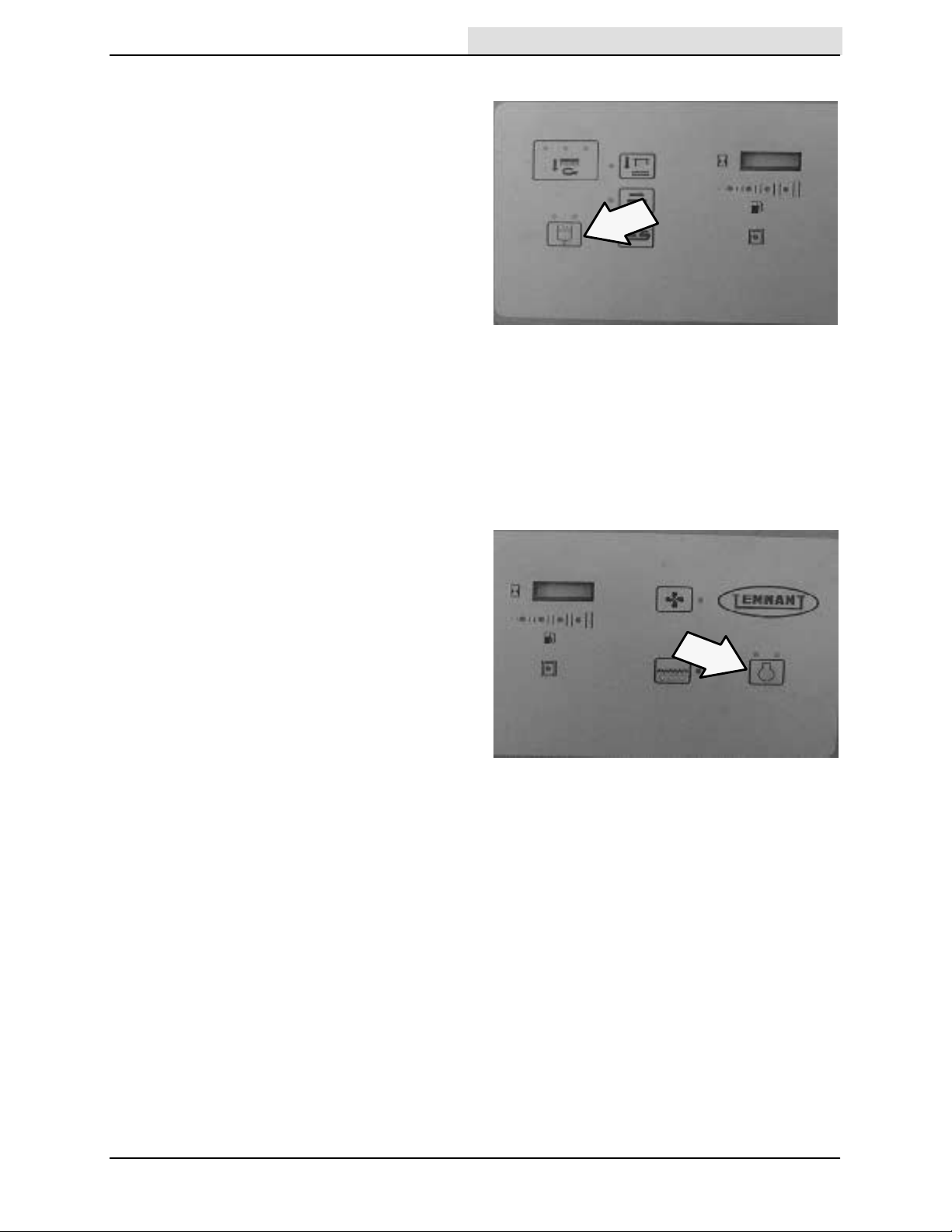
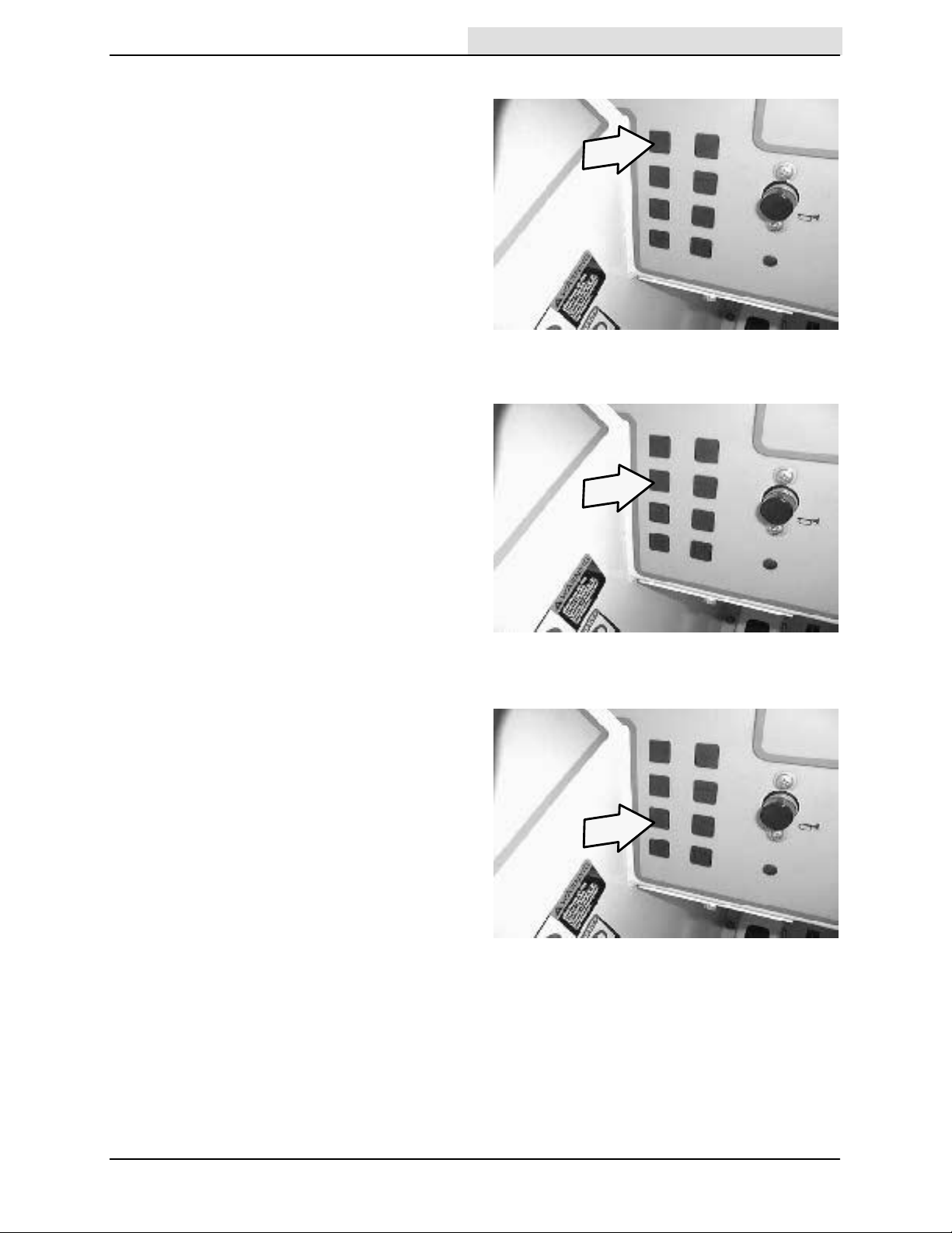
SCRUB SWITCH
The scrub switch controls the scrubbing
operations. The scrub switch also sets the scrub
brush pressure.
The scrubbing operations include the functions
described below . When the machine is moving
forward, the scrub head lowers and the scrub
brushes activate. The scrub head will move into
the edge scrub position if the edge scrub switch
(option) is pressed. The rear squeegee will lower
and the vacuum fan will start. The solution system
will start, if the solution flow switch is on. Also, the
optional ES system and detergent pump will start
if the switches are on. The engine speed will
change to fast.
Start: Press the scrub switch.
Stop: Press the scrub switch again.
Scrub brush pressure: Press and hold the scrub
switch. The brush pressure will scroll through
three settings. The pressure setting selected
when the switch is released will be the new
default brush pressure setting.
Thebrushpressurecanbesetintothreedifferent
positions. Under normal conditions, the brush
pressure should be set in the minimum settings
(one or two indicators above switch are lit). Under
heavy grime conditions, the brush pressure
should be set in the maximum setting (three
indicators above switch are lit). Travel speed and
floor conditions will affect the scrubbing
performance.
NOTE: The brush pressure setting, and the
detergent flow rate will default to the last settings
used when the scrubbing operations are started
again.
NOTE: The scrub head will raise when the
directional pedal is in the neutral position. The
rear squeegee will raise when the directional
pedal is in the reverse position.
18
8200 330060 (1-- 98)
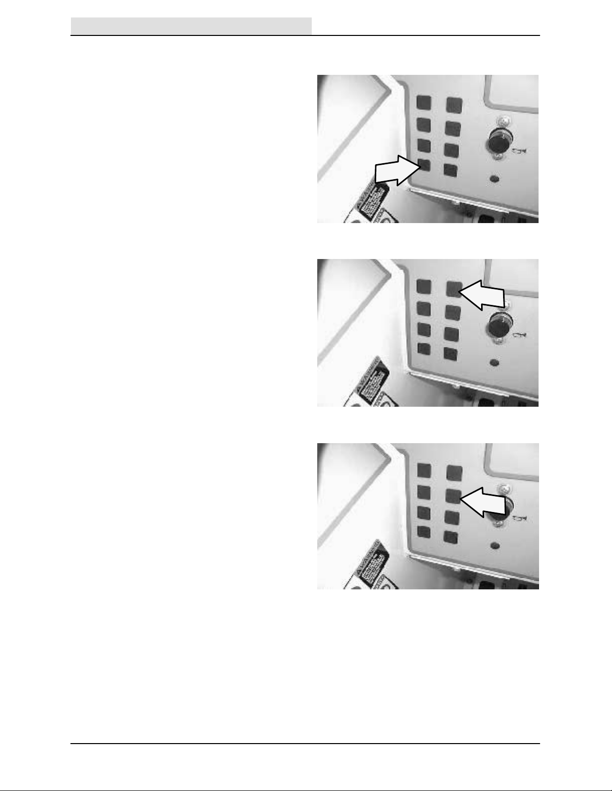
SQUEEGEE SWITCH
Home
Find...
Go To..
The squeegee switch controls the position of the
rear squeegee. The rear squeegee can be
operated separately from the scrub brushes for
the purpose of double scrubbing.
Double scrubbing is the process of making two or
more passes over a heavily soiled area. The first
pass is made with the rear squeegee raised to
allow the solution to soak into the floor.
Lower: Press the squeegee switch. The indicator
light next to the switch will illuminate.
Raise and stop: Press the squeegee switch. The
indicator next to the switch goes off. There will be
a slight delay before the vacuum shuts off.
NOTE: The rear squeegee lowers and scrubbing
vacuum starts automatically when the scrubbing
operations start.
NOTE: The rear squeegee will raise and the
scrubbing vacuum will shut off after a short delay
when the machine travels in reverse.
OPERATION
NOTE: The rear squeegee will raise and the
scrubbing vacuum fan will shut off after a short
delay when the scrubbing operations are shut off.
EDGE SCRUB SWITCH (OPTION)
The edge scrub switch extends the scrub head to
the right to allow close edge scrubbing.
Edge scrub out: Press the edge scrub switch
during scrubbing. The indicator light next to the
switch will illuminate.
Edge scrub in: Press the edge scrub switch. The
indicator light next to the switch will go out.
8200 330060 (1-- 98)
19
OPERATION
Home
Find...
Go To..
ES SWITCH (OPTION)
The ES switch turns the extended scrub system
on and off . When the machine is started, the ES
switch will default to the last setting used.
On: Press the ES switch. The indicator light next
to the switch will illuminate.
Off: Press the ES switch. The indicator light next
to the switch will go out.
NOTE: When the ES switch is on and the water
levels in the tanks are at the proper levels, there
will be a slight delay before the ES pump turns on.
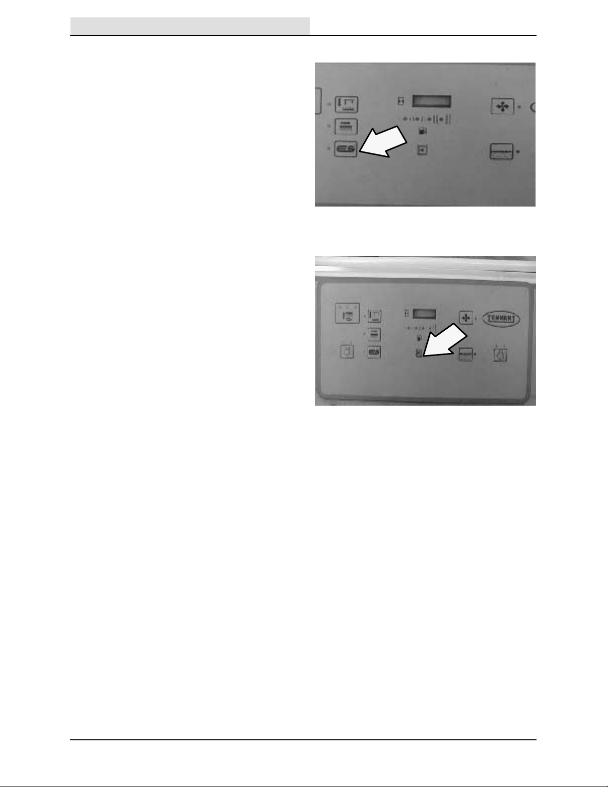
RECOVERY TANK FULL INDICATOR
The recovery tank full indicator will illuminate
when the recovery tank is full of recovered
solution. All scrubbing functions will stop
automatically soon after the recovery tank
becomes full. Drain the recovery tank as soon as
possible after the indicator illuminates. The
indictor light will remain lit until the tank is drained.
20
8200 330060 (6-- 04)
DETERGENT PUMP SWITCH (OPTION)
Home
Find...
Go To..
The detergent switch controls the amount of
detergent that flows to the floor while scrubbing.
When the machine is started, the detergent pump
switch will default to the last setting used.
NOTE: The detergent pump switch will not
activate unless the main scrub brushes are active,
the machine is moving forward, and the solution
switch is in the high or low position.
High: Press and hold the detergent pump switch
until both indicator lights above the switch are
illuminated. Release the switch.
Low: Press and hold the detergent pump switch
until one indicator light above the switch is
illuminated. Release the switch.
Off: Press and release the detergent pump switch
until none of the indicator lights above the switch
are lit.
OPERATION
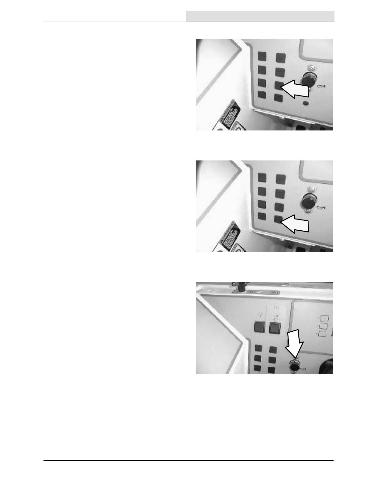
ENGINE SPEED SWITCH
The engine speed switch controls the engine
governed speed. When the left indicator light
above the switch is illuminated, the engine is in
idle speed. When the right indicator light above
the switch is illuminated, the engine is in fast
speed.
Idle speed: The engine will automatically start in
idle speed. To return the engine to idle from the
fast engine speed, press and hold the engine
speed switch until the left indicator illuminates.
The scrubbing and sweeping operations will turn
off automatically.
NOTE: If the scrubbing operations are on when
the idle speed is selected, the rear squeegee will
raise and the scrubbing vacuum fan will shut off.
Fast speed: Press and hold the engine speed
switch until the right indicator light illuminates.
This speed is for transporting, sweeping, and
scrubbing.
NOTE: The engine will automatically operate in
the fast speed when the scrubbing or sweeping
operations are started.
8200 330060 (1-- 98)
21
OPERATION
Home
Find...
Go To..
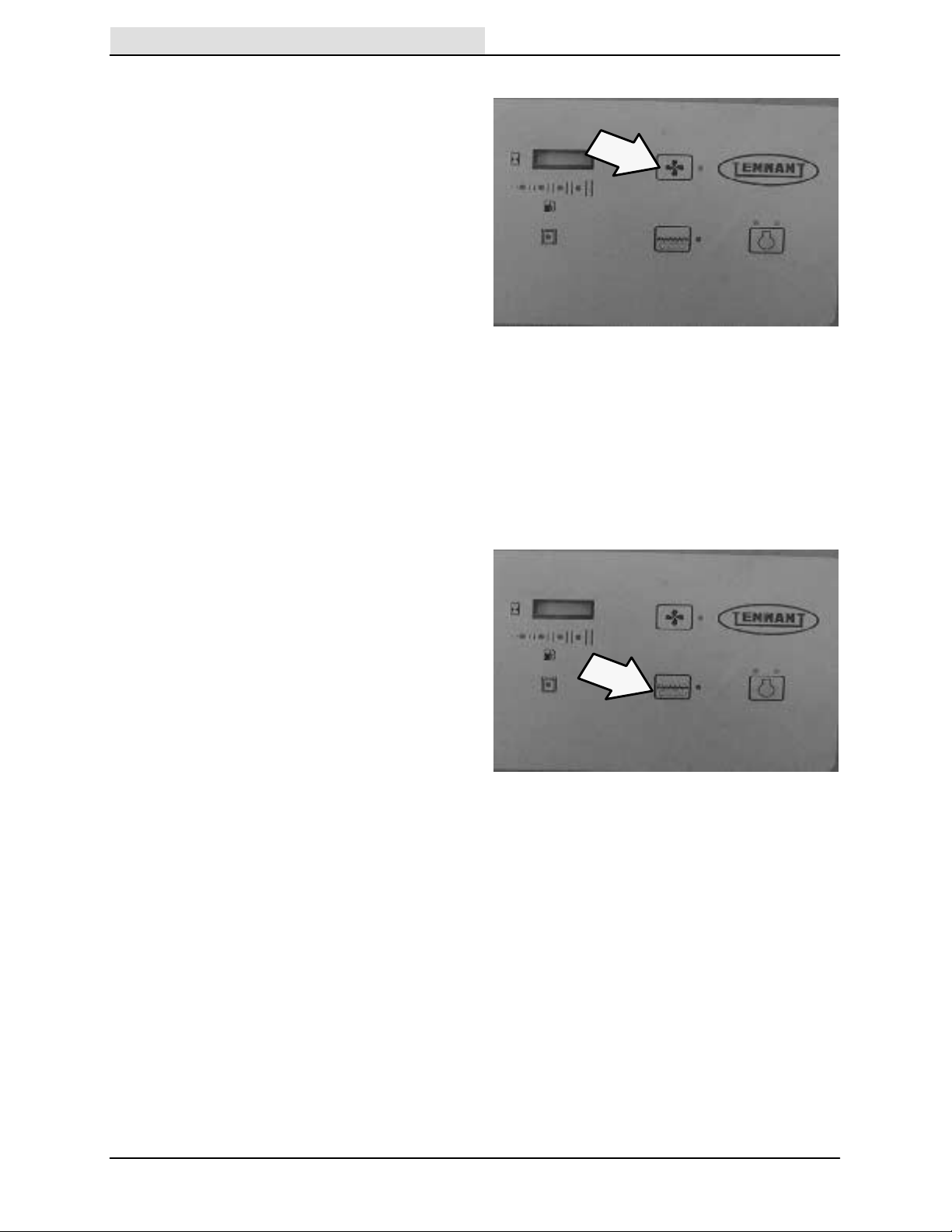
SWEEPING VACUUM FAN SWITCH
The sweep vacuum fan switch starts and stops
the sweep vacuum fan. Do not operate the
vacuum fan when sweeping in wet conditions.
Start: Press the switch. The indicator next to the
switch will illuminate.
Stop: Press the switch. The indicator light next to
the switch will go out.
NOTE: The sweep vacuum fan activates
automatically when the main sweeping brush
starts operating. The sweep vacuum fan will not
activate unless the main sweeping brush is
operating.
NOTE: The sweep vacuum fan will not start if the
hopper is raised, even slightly. If the sweep
vacuum fan switch is pressed while the hopper is
raised, the sweep vacuum will not start.
FILTER SHAKER SWITCH
The filter shaker switch starts the hopper dust
filter shaker. The shaker automatically operates
for 30 seconds.
Start: Press the filter shaker switch. The indicator
light will remain on while the filter shaker is
operating.
NOTE: The filter shaker will activate automatically
for a short time each time the sweeping
operations are stopped. The filter shaker will not
operate while the sweeping or vacuum system is
operating.
22
8200 330060 (1-- 98)
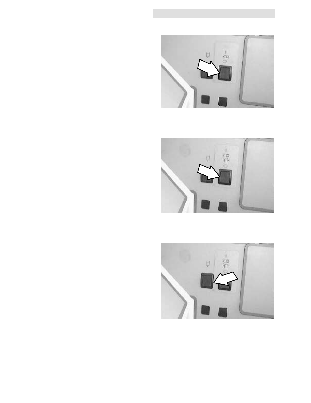
OPERATING LIGHTS SWITCH
Home
Find...
Go To..
The operating lights switch powers the headlights
and taillights on and off.
On: Press the top of the operating lights switch.
Off: Press the bottom of the operating lights
switch.
OPERATING/HAZARD LIGHT SWITCH
(OPTION)
The operating/hazard light switch powers the
headlights and taillights, and the revolving hazard
light (option) on and off.
OPERATION
Operating lights on: Press the top of the hazard
light switch.
Operating lights/Hazard light (option) on: Press
the bottom of the hazard light switch.
All lights off: Set the the hazard light switch in the
middle position.
SOLUTION FLOW SWITCH
The solution flow switch controls the amount of
solution that flows to the floor while scrubbing.
(1) Low: Press the top of the switch. Use this flow
rate for smooth floors and light dirt.
(0) Off: Press the middle of the switch.
(2) High: Press the bottom of the switch. Use this
flow rate for rough floors and heavy or compacted
dirt.
1
0
2
8200 330060 (1-- 98)
23
OPERATION
Home
Find...
Go To..
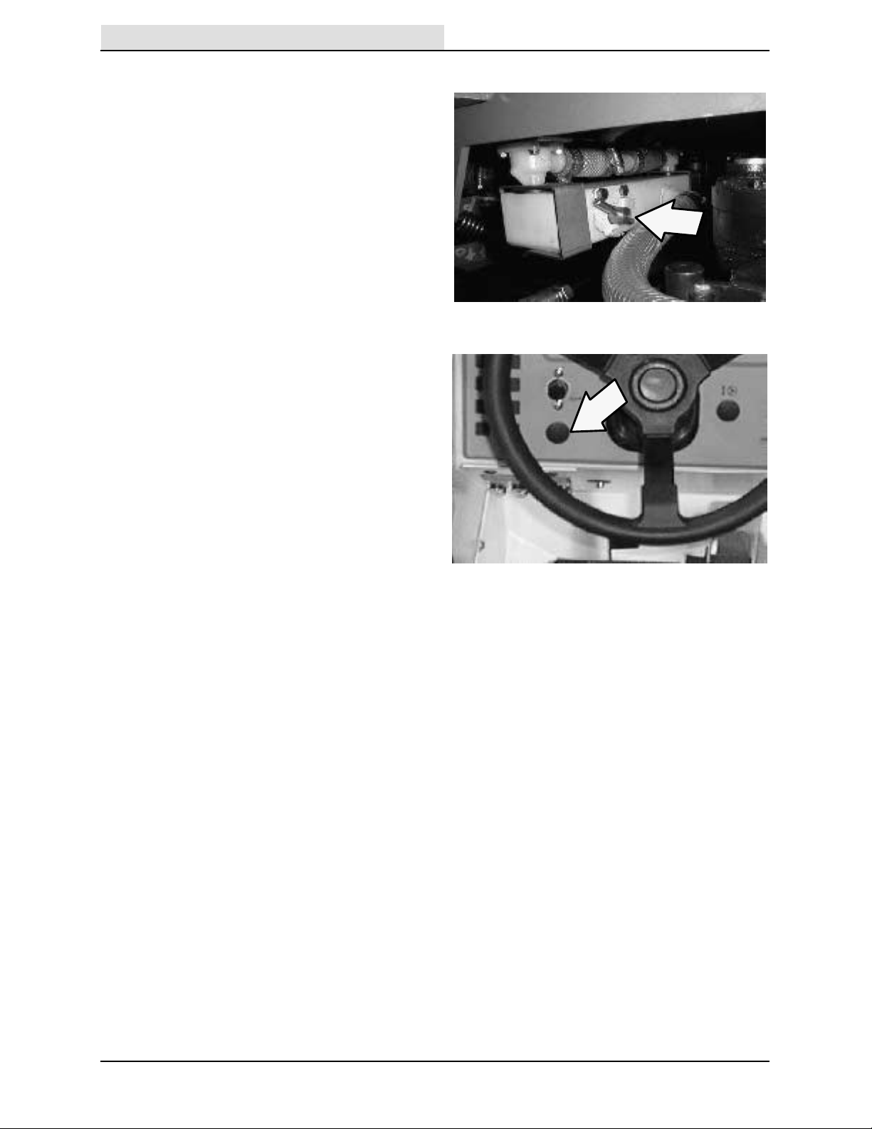
MANUAL FLOW VALVE
The machine is equipped with a manually
adjustable solution flow valve that is located on
the right side of the scrubhead. The valve can be
adjusted to dispense either more or less solution.
Contact your TENNANT representative with
solution flow rate questions.
Maximum flow: Turn the flow lever to the
horizontal position.
Minimum flow: Turn the flow lever to the vertical
position.
ENGINE CHOKE KNOB (FORD ENGINE)
The engine choke knob controls the engine choke
on FORD gasoline powered machines.
On: For cold starting, pull the engine choke knob
out.
Off: Push the engine choke knob in.
24
8200 330060 (6-- 04)
CHARGING SYSTEM LIGHT
Home
Find...
Go To..
The charging system light will illuminate when the
alternator is not operating within the normal range.
If the light illuminates stop the machine
immediately, then find the problem and have it
corrected.
ENGINE OIL PRESSURE LIGHT
The engine oil pressure light will illuminate when
the engine oil pressure falls below 40 kPa (5 psi).
In this situation, an alarm will sound until the oil
pressure problem is corrected. If the light
illuminates stop the machine immediately, then
find the problem and have it corrected.
OPERATION
ENGINE WATER TEMPERATURE LIGHT
The engine water temperature light will illuminate
when the temperature of the engine coolant is
more than 107_ C (225_ F). If the light illuminates
stop the machine immediately, then find the
problem and have it corrected.
8200 330060 (11--98)
25
OPERATION
Home
Find...
Go To..
HOPPER TEMPERATURE LIGHT -THERMO SENTRY
The hopper temperature light will illuminate when
there is too much heat, possibly from a fire, in the
hopper. The Thermo Sentry will stop the sweeping
vacuum fan. If the light illuminates stop the
machine immediately, then find the problem and
have it corrected.
OK LIGHT
Each time the key switch is turned to the on
position the instrument panel will run a
self--diagnostic test. If the instrument panel
passes the test, the OK light will illuminate.
CLOGGED FILTER LIGHT (OPTION)
The clogged filter light will illuminate when the
hopper dust filter is clogged.
To clean the filter, press the filter shaker switch. If
the clogged filter light remains lit, manually clean
the hopper dust filter. See HOPPER DUST
FILTER in the MAINTENANCE section of this
manual.
26
8200 330060 (6-- 04)
HOPPER DOOR CLOSED LIGHT (OPTION)
Home
Find...
Go To..
The hopper door closed light will illuminate when
the hopper door is closed.
Make sure the the hooper door is open (the light
will be out), while sweeping.
HYDRAULIC FILTER BYPASS LIGHT (OPTION)
The hydraulic filter bypass light will illuminate
when the hydraulic filter becomes clogged. If the
light illuminates stop the machine immediately,
then change the hydraulic filter and hydraulic fluid
as soon as possible.
OPERATION
HORN BUTTON
The horn button operates the horn.
Sound: Press the button.
8200 330060 (1-- 98)
27
OPERATION
Home
Find...
Go To..
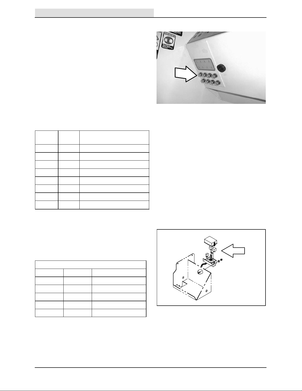
CIRCUIT BREAKERS
The circuit breakers are resetable electrical circuit
protection devices. Their design stops the flow of
current in the event of a circuit overload. Once a
circuit breaker is tripped, it must be reset
manually. Press the reset button after the breaker
has cooled down.
If the overload that caused the circuit breaker to
trip is still there, the circuit breaker will continue to
stop current flow until the problem is corrected.
The circuit breakers are located in the operator
compartment.
The chart lists the circuit breakers and the
electrical components they protect.
Circuit
Breaker
CB-1 15 A Horn
CB-2 15 A Ignition
CB-3 15 A Headlights / Taillights
CB-4 5A Logic Power
CB-5 15 A Sweeping
CB-6 15 A Scrubbing Accessories
CB-7 15 A Scrubbing Brushes
CB-8 15 A Filter Shaker Motor
Rating Circuit Protected
FUSES (GM ENGINE)
On machines with the GM engine, there are
engine harness fuses that are located on the
battery box inside the engine side door. Access
the fuses by opening the engine side door.
Engine Harness Fuses
Fuse Rating Circuit Protected
FU-1 5A Key switch
FU-2 20 A Main power
FU-3 15 A Auxilary power
FU-4 15 A Fuel pump
FU-5 50 A Alternator
28
8200 330060 (6-- 04)
 Loading...