

Tennant 7400 User Manual
7400
Home
Find...
Go To..
(Gas/LPG)
(007000-- )
(GM Engine)
Rider Scrubber
Operator Manual
The Safe Scrubbing Alternative
R
ES Extended Scrub System
R
North America / International
www.tennantco.com
330970
Rev. 04 (3-2007)
*330970*
This manual is furnished with each new model. It provides necessary operation and maintenance instructions.
Home
Find...
Go To..
Read this manual completely and understand the machine before operating or servicing it.
This machine will provide excellent service. However, the best results will be obtained at minimum costs if:
S The machine is operated with reasonable care.
S The machine is maintained regularly - per the machine maintenance instructions provided.
S The machine is maintained with manufacturer supplied or equivalent parts.
PROTECT THE ENVIRONMENT
Please dispose of packaging materials,
old machine components such as
batteries, hazardous fluids such as
antifreeze and oil, in an environmentally
safe way according to local waste
disposal regulations.
Always remember to recycle.
MACHINE DATA
Please fill out at time of installation for future reference.
Model No. --
Serial No. --
Machine Options --
Sales Rep. --
Sales Rep. phone no. --
Customer Number --
Installation Date --
Tennant Company
PO Box 1452
Minneapolis, MN 55440
Phone: (800) 553--8033 or (763) 513--2850
www.tennantco.com
CALIFORNIA PROPOSITION 65 WARNING:
Engine exhaust from this product contains chemicals known to the State of California to cause cancer,
birth defects, or other reproductive harm.
FaST--PAK is a US registered and unregistered trademark of Tennant Company.
Specifications and parts are subject to change without notice.
Copyright E 1998-- 2000, 2002--2007 TENNANT Company, Printed in U.S.A.

CONTENTS
Home
Find...
Go To..
CONTENTS
Page
SAFETY PRECAUTIONS 3.................
OPERATION 7..............................
OPERATOR RESPONSIBILITY 7.........
MACHINE COMPONENTS 8.............
SYMBOL DEFINITIONS 9................
CONTROLS AND INSTRUMENTS 10......
OPERATION OF CONTROLS 11..........
DIRECTIONAL PEDAL 11..............
BRAKE PEDAL 12....................
PARKING BRAKE PEDAL 12...........
CHARGING SYSTEM LIGHT 12........
ENGINE OIL PRESSURE LIGHT 13.....
HIGH ENGINE TEMPERATURE
LIGHT 13..........................
MAINTENANCE MODE LIGHT 13.......
RECOVERY TANK FULL LIGHT 14.....
FUEL LEVEL LOW LIGHT 14...........
OK LIGHT 14.........................
FUEL LEVEL GAUGE 15...............
HOURMETER 15.....................
SQUEEGEE SWITCH 15................
ES SWITCH (OPTION) 16...............
SIDE BRUSH SWITCH (OPTION) 16.....
DETERGENT FLOW SWITCH
(OPTION) 16.......................
SCRUB SWITCH 17....................
ENGINE SPEED SWITCH 18............
STEERING WHEEL 18.................
COVER RELEASE KNOB 18............
HORN BUTTON 19.....................
IGNITION SWITCH 19..................
STEERING COLUMN TILT HANDLE 19...
CHECK ENGINE LIGHT 20..............
CIRCUIT BREAKERS 20................
FUSES 21.............................
SOLUTION FLOW SWITCH
(WITHOUT FaST) 22................
SOLUTION FLOW SWITCH (FaST) 22...
FaST SWITCH 22......................
SOLUTION TANK DRAIN HOSE 23......
RECOVERY TANK DRAIN HOSE 23.....
OPERATOR SEAT 24...................
LATCHES 24..........................
HOW THE MACHINE WORKS 25...........
FaST SCRUBBING SYSTEM 26............
PRE-OPERATION CHECKLIST 27..........
INSTALLING FaST PAK AGENT 28.........
CHANGING AN LPG FUEL TANK 30........
STARTING THE MACHINE 31..............
SCRUBBING AND BRUSH INFORMA TION 33
FILLING THE TANKS 34...................
SCRUBBING 36
DOUBLE SCRUBBING 39..................
STOP SCRUBBING 39....................
DRAINING AND CLEANING THE TANKS 40.
STOP THE MACHINE 43..................
7400 (GM) 330970 (3-- 07)
..........................
Page
POST-OPERATION CHECKLIST 45.........
OPERATION ON INCLINES 45.............
OPTIONS 46.............................
VACUUM WAND 46....................
MACHINE TROUBLESHOOTING 49........
MAINTENANCE 52..........................
MAINTENANCE CHART 52................
LUBRICATION 54.........................
ENGINE 54............................
REAR WHEEL BEARINGS 54...........
FRONT WHEEL SUPPORT BEARING 54.
SCRUB BRUSH IDLER 55..............
HYDRAULICS 55.........................
HYDRAULIC FLUID RESERVOIR 55.....
HYDRAULIC FLUID 56.................
HYDRAULIC HOSES 56................
ENGINE 57..............................
COOLING SYSTEM 57.................
AIR FILTER INDICATOR 59............
AIR FILTER 60........................
SPARK PLUGS 60....................
CRANKCASE VENTILATION SYSTEM 60
TIMING BELT 60......................
FUEL FILTER (GASOLINE) 60..........
FUEL FILTER (LPG) 61................
ELECTRONIC PRESSURE REGULATOR
(LPG) (For machines serial number
009000 and above) 61............
ELECTRONIC FUEL INJECTION 61.....
BATTERY 62............................
PROPELLING MOTOR 62................
BELTS AND CHAINS 62..................
ENGINE BELT 62.....................
STATIC DRAG CHAIN 62..............
SCRUB BRUSHES 63....................
REPLACING OR ROTATING THE
SCRUB BRUSHES 64.................
CHECKING AND ADJUSTING
SCRUB BRUSH PATTERN 65.......
SOLUTION SYSTEM 68..................
RECOVERY TANK 68.................
SOLUTION TANK 68..................
DEBRIS TRAY 68........................
FaST SYSTEM 69.......................
FaST SUPPLY HOSE CONNECTOR 69.
FaST SYSTEM FILTER SCREEN 69....
FaST SYSTEM AIR PUMP FILTER 69...
FaST SPRAY TUBE 70................
SQUEEGEES 70.........................
ADJUSTING REAR SQUEEGEE
BLADE DEFLECTION 70............
LEVELING THE REAR SQUEEGEE 72..
1

CONTENTS
Home
Find...
Go To..
Page
SQUEEGEE BLADES 73.................
REAR SQUEEGEE 73.................
REPLACING OR ROTATING REAR
SQUEEGEE BLADES 73............
SIDE SQUEEGEES 74................
REPLACING SIDE SQUEEGEE
BLADES 74.....................
SKIRTS AND SEALS 75..................
SCRUB HEAD SKIRTS 75.............
COVER SEALS 75....................
BRAKES AND TIRES 76..................
SERVICE BRAKES 76.................
PARKING BRAKE 76..................
TIRES 76............................
FRONT WHEEL 76....................
PUSHING, TOWING, AND
TRANSPORTING THE MACHINE 77....
PUSHING OR TOWING THE MACHINE 77
TRANSPORTING THE MACHINE 78....
MACHINE JACKING 80...................
STORING MACHINE 80..................
OPTIONS 81.
SIDE BRUSH 81......................
REPLACING THE SIDE
SCRUB BRUSH 81..............
REPLACING THE SQUEEGEE
BLADE 82......................
SIDE BRUSH SKIRT 82................
SPECIFICATIONS 83.......................
GENERAL MACHINE PERFORMANCE 83..
FaST SYSTEM 83.......................
POWER TYPE 84........................
STEERING 84...........................
HYDRAULIC SYSTEM 84.................
MACHINE DIMENSIONS 85...............
INDEX 86...................................
2
7400 (GM) 330970 (3-- 07)
SAFETY PRECAUTIONS
Home
Find...
Go To..
SAFETY PRECAUTIONS
The following precautions are used throughout
this manual as indicated in their description:
WARNING: To warn of hazards or
unsafe practices that could result in
severe personal injury or death.
CAUTION: To warn of unsafe practices
that could result in minor or moderate
personal injury.
FOR SAFETY: To identify actions that
must be followed for safe operation of
equipment.
The machine is suited to sweep disposable
debris. Do not use the machine other than
described in this Operator Manual. The machine
is not designed for use on public roads.
The following information signals potentially
dangerous conditions to the operator or
equipment:
WARNING: Flammable materials can
cause an explosion or fire. Do not use
flammable materials in tank(s).
WARNING: Flammable materials or
reactive metals can cause an explosion
or fire. Do not pickup.
WARNING: Moving belt and fan. Keep
away.
WARNING: Strong Vacuum. Keep Away
From Fan Inlet When Fan Is Running.
WARNING: Engine emits toxic gases.
Severe respiratory damage or
asphyxiation can result. Provide
adequate ventilation. Consult with your
regulatory authorities for exposure
limits. Keep engine properly tuned.
FOR SAFETY:
1. Do not operate machine:
-- Unless trained and authorized.
-- Unless operator manual is read and
understood.
-- If it is not in proper operating
condition.
-- In flammable or explosive areas unless
designed for use in those areas.
-- In areas with possible falling objects
unless equipped with overhead guard.
2. Before starting machine:
-- Check for fuel, oil, and liquid leaks.
-- Keep sparks and open flame away
from refueling area.
-- Make sure all safety devices are in
place and operate properly.
-- Check brakes and steering for proper
operation.
3. When starting machine:
-- Keep foot on brake and directional
pedal in neutral.
4. When using machine:
-- Use brakes to stop machine.
-- Go slow on inclines and slippery
surfaces.
-- Use care when reversing machine.
-- Do not carry passengers on machine.
-- Always follow safety and traffic rules.
-- Report machine damage or faulty
operation immediately.
-- Follow mixing and handling
instructions on chemical containers.
5. Before leaving or servicing machine:
-- Stop on level surface.
-- Set parking brake.
-- Turn off machine and remove key .
WARNING: Hot bumper. Keep away.
CAUTION: LPG engine will run for a few
seconds after key is turned off. Apply
parking brake before leaving machine.
7400 (GM) 330970 (12-- 05)
3

SAFETY PRECAUTIONS
Home
Find...
Go To..
6. When servicing machine:
-- Avoid moving parts. Do not wear loose
jackets, shirts, or sleeves.
-- Block machine tires before jacking
machine up.
-- Jack machine up at designated
locations only. Block machine up with
jack stands.
-- Use hoist or jack that will support the
weight of the machine.
-- Wear eye and ear protection when
using pressurized air or water.
-- Disconnect battery connections before
working on machine.
-- Avoid contact with battery acid.
-- Avoid contact with hot engine coolant.
-- Allow engine to cool.
-- Keep flames and sparks away from
fuel system service area. Keep area
well ventilated.
-- Use cardboard to locate leaking
hydraulic fluid under pressure.
-- Use Tennant supplied or approved
replacement parts.
7. When loading/unloading machine
onto/off truck or trailer:
-- Turn off machine.
-- Use truck or trailer that will support
the weight of the machine.
-- Use winch. Do not drive the machine
onto/off the truck or trailer unless the
load height is 380 mm (15 in) or less
from the ground.
-- Set parking brake after machine is
loaded.
-- Block machine tires.
-- Tie machine down to truck or trailer.
4
7400 (GM) 330970 (12-- 05)
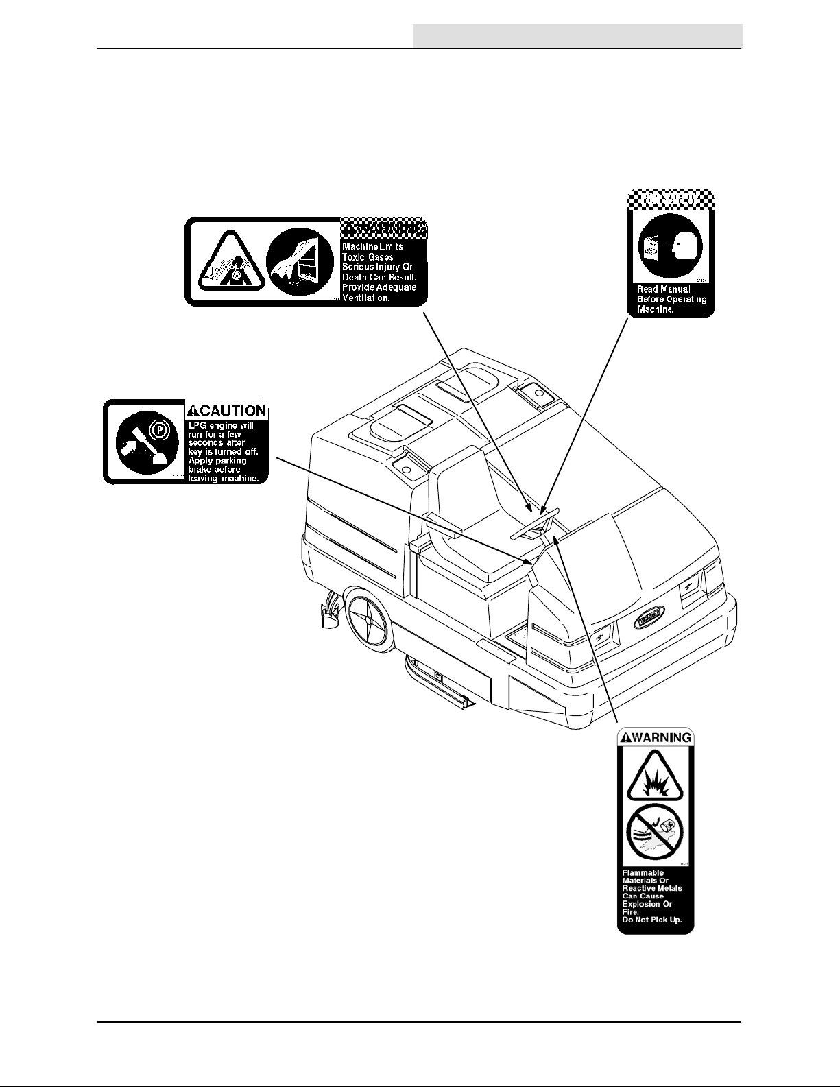
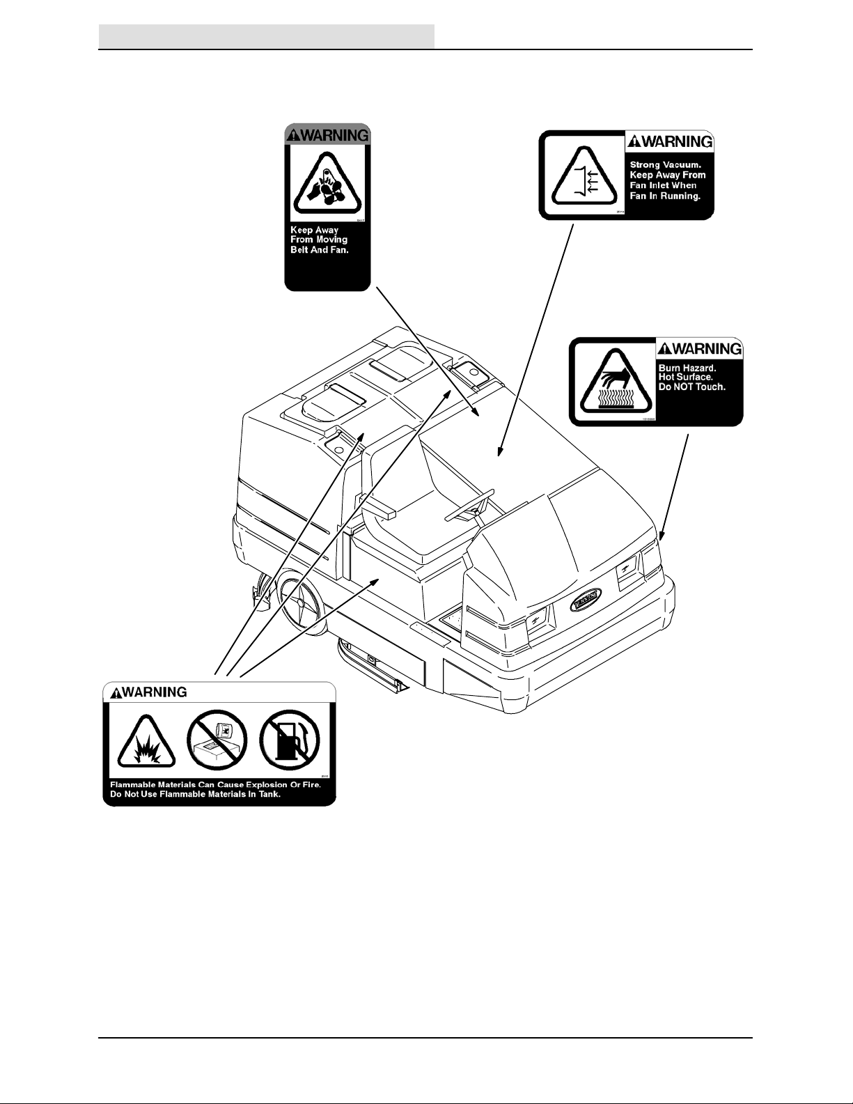
The following safety labels are mounted on the
Home
Find...
Go To..
machine in the locations indicated. If these or any
labels become damaged or illegible, install a new
label in its place.
EMISSIONS LABEL -- LOCATED ON THE SIDE
OF THE OPERATOR COMPARTMENT.
LPG ENGINE WILL RUN LABEL -- LOCATED
NEXT TO THE IGNITION SWITCH ON THE
INSTRUMENT PANEL.
SAFETY PRECAUTIONS
FOR SAFETY LABEL -- LOCATED ON THE
SIDE OF THE OPERATOR COMP ARTMENT.
7400 (GM) 330970 (12-- 05)
10783
FLAMMABLE SPILLS LABEL -- LOCATED ON
THE SIDE OF THE OPERATOR
COMPARTMENT.
5
SAFETY PRECAUTIONS
Home
Find...
Go To..
FAN AND BELT LABEL -- LOCATED ON THE
ENGINE COMPARTMENT LINTEL.
STRONG VACUUM LABEL -- LOCATED ON
THE VACUUM FAN HOUSING.
HOT SURFACE LABEL -LOCATED ON THE SIDE OF
THE BUMPER.
FLAMMABLE MATERIALS LABEL -- LOCATED
NEXT TO THE SOLUTION TANK COVERS AND
ON THE DETERGENT TANK.
6
10783
7400 (GM) 330970 (9-- 04)
OPERATOR RESPONSIBILITY
Home
Find...
Go To..
- The operator’s responsibility is to take care
of the daily maintenance and checkups of
the machine, to keep it in good working
condition. The operator must inform the
service mechanic or supervisor when the
required maintenance intervals occur as
stated in the MAINTENANCE section of this
manual.
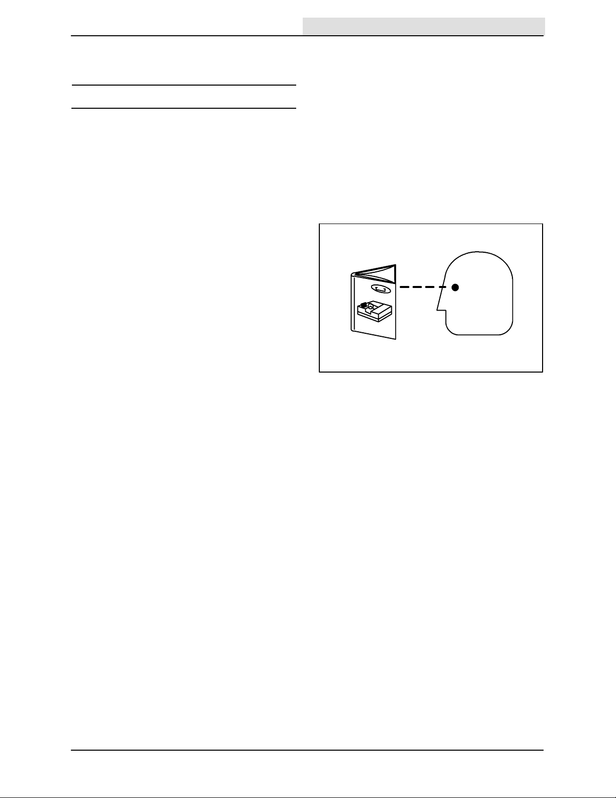
- Read this manual carefully before operating
this machine.
FOR SAFETY: Do not operate machine,
unless operation manual is read and
understood.
- Check the machine for shipping damage.
Check to make sure the machine is
complete per shipping instructions.
OPERATION
OPERATION
- Keep your machine regularly maintained by
following the maintenance information in this
manual. We recommend taking advantage
of a regularly scheduled service contract
from your Tennant representative.
- Order parts and supplies directly from your
authorized Tennant representative. Use the
parts manual provided when ordering parts.
- After the first 50 hours of operation, follow
the recommended procedures stated in the
MAINTENANCE CHART.
07324
7400 (GM) 330970 (12-- 03)
7
OPERATION
Home
Find...
Go To..
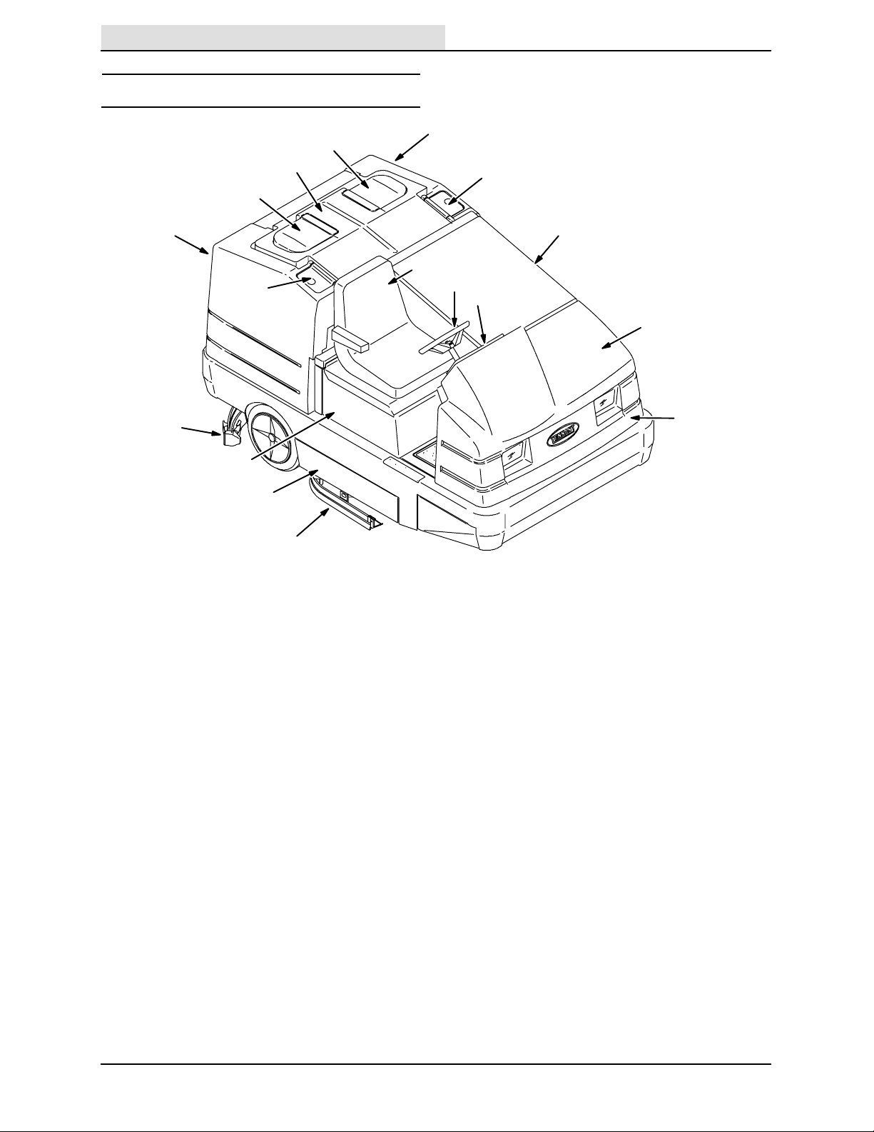
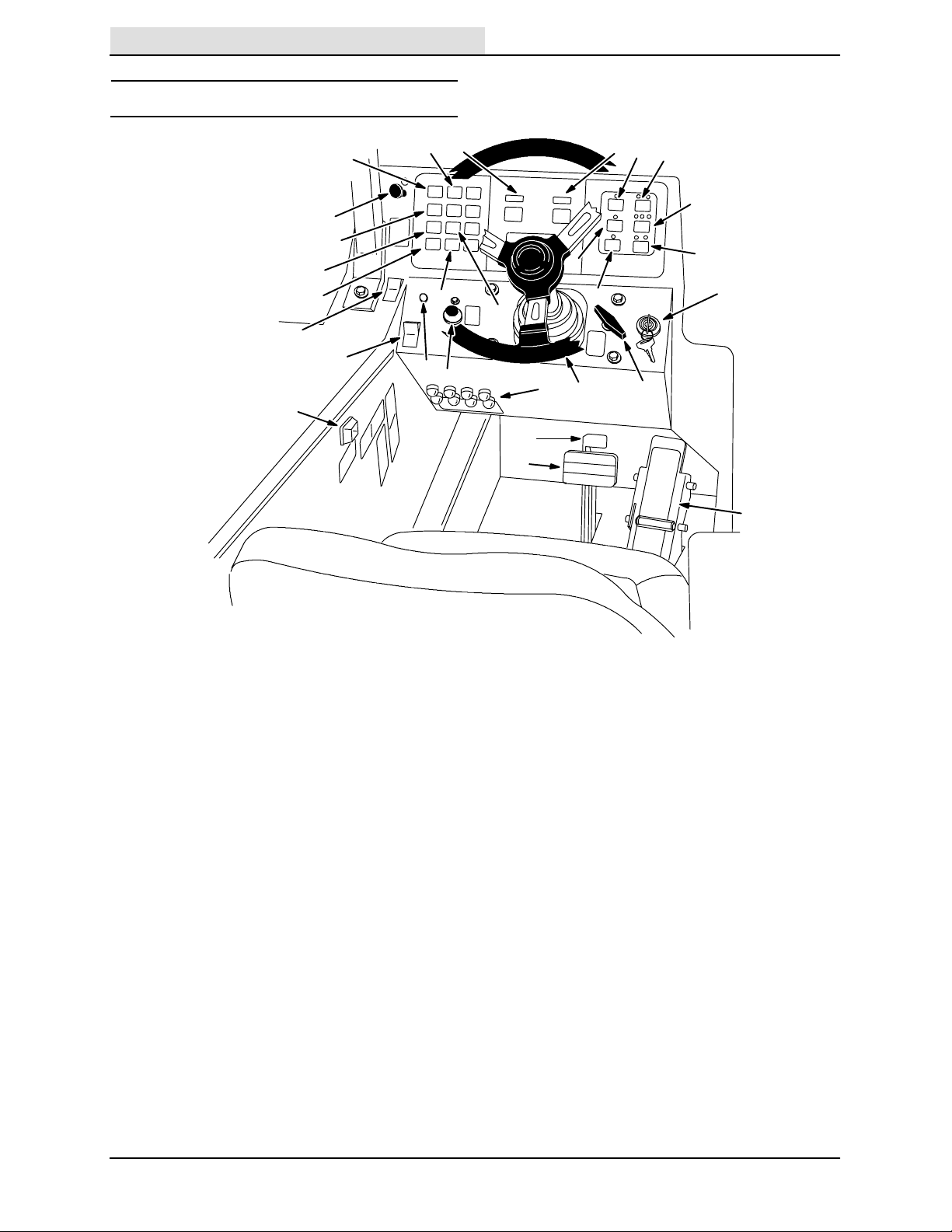
MACHINE COMPONENTS
H
I
H
G
F
J
M
L
G
F
D
C
B
A
E
N
K
A. Instrument panel
B. Steering wheel
C. Operator seat
D. Engine cover
E. Machine front cover
F. Solution tank covers
G. Solution tanks
H. Recovery tank covers
I. Recovery Tank
J. Rear squeegee
K. Side Squeegee
L. Scrub brush access door
M. FaST solution system
N. Fuel tank
10783
8
7400 (GM) 330970 (3-- 07)
SYMBOL DEFINITIONS
Home
Find...
Go To..
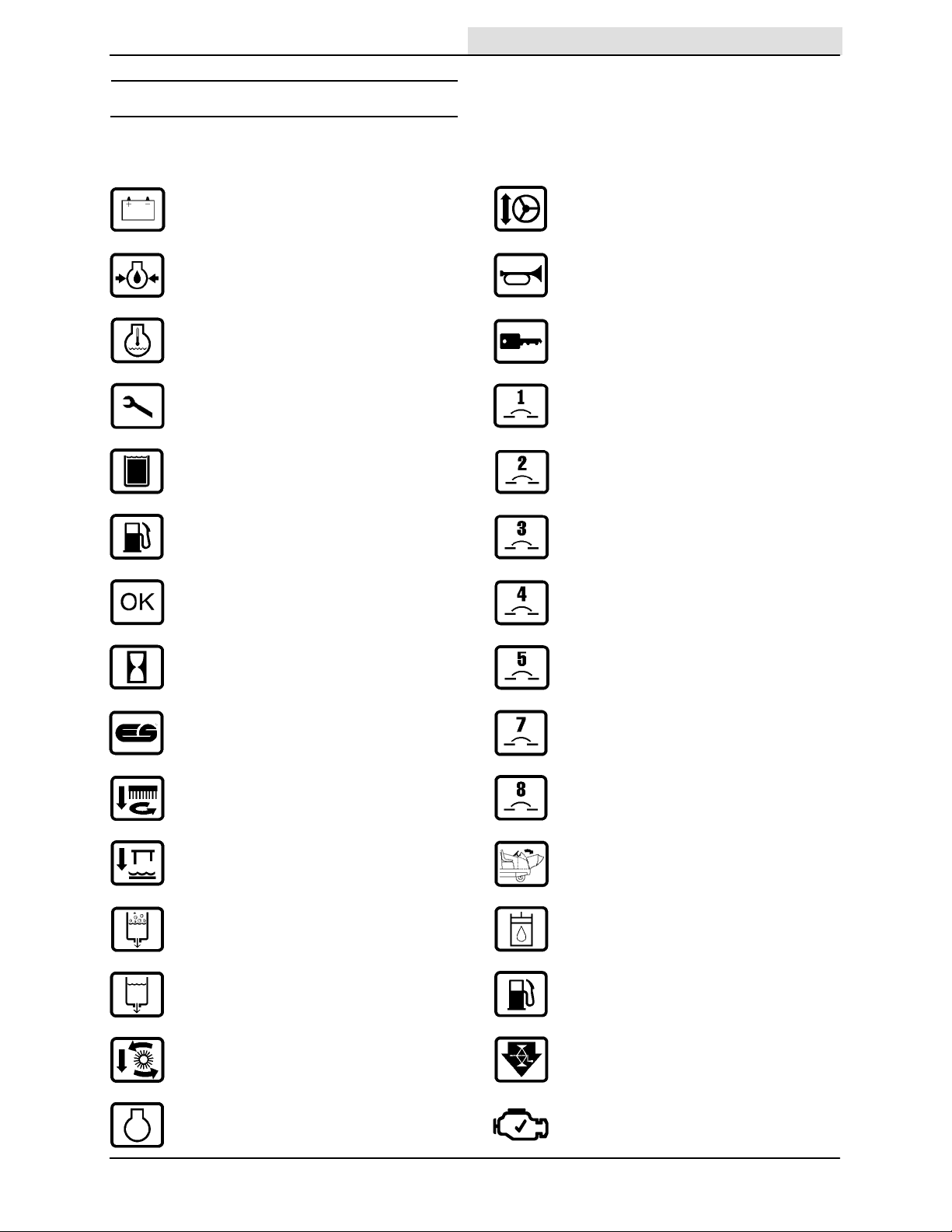
These symbols identify controls, displays, and
features on the machine:
Charging system Steering tilt
Engine oil pressure Horn
High engine temperature Ignition switch
Maintenance mode Circuit breaker 1
Recovery tank full Circuit breaker 2
OPERATION
Fuel Circuit breaker 3
Diagnostics Circuit breaker 4
Hourmeter Circuit breaker 5
ES Circuit breaker 7
Side brush down and on Circuit breaker 8
Rear squeegee down and vacuum on Cover release
Detergent flow Hydraulic fluid only
Solution flow Gasoline fuel only
Scrub brushes down and on Jack-point
Engine Check Engine
7400 (GM) 330970 (3-- 07)
9
OPERATION
Home
Find...
Go To..
CONTROLS AND INSTRUMENTS
AA
X
K
D
Y
E
F
G
BB
H
J
Z
T
I
W
C
B
L
M
P
Q
N
O
S
V
R
U
A
A. Directional pedal
B. Brake pedal
C. Parking brake pedal
D. Charging system light
E. Engine oil pressure light
F. High engine temperature light
G. Maintenance mode light
H. Recovery tank full light
I. Fuel level low light
J. OK light
K. Fuel level gauge
L. Hourmeter
M. ES switch (option)
N. Side brush switch (option)
O. Squeegee switch
P. Detergent flow switch (option)
Q. Scrub switch
R. Engine speed switch
S. Steering wheel
T. Horn button
U. Ignition switch
V. Steering column tilt lever
W. Circuit breakers
X. Solution flow switch
Y. Cover release knob
Z. Check engine light
AA.FaST switch
BB.FaST solution flow switch
10654
10
7400 (GM) 330970 (3-- 07)
OPERATION OF CONTROLS
Home
Find...
Go To..
DIRECTIONAL PEDAL
The directional pedal controls direction of travel
and the propelling speed of the machine. You
change the speed of the machine with the
pressure of your foot; the harder you press the
faster the machine travels.
Forward: Press the top of the directional pedal
with the toe of your foot.
OPERATION
Reverse: Press the bottom of the directional
pedal with the heel of your foot.
Neutral: Take your foot off the directional pedal
and it will return to the neutral position.
7400 (GM) 330970 (12-- 03)
11
OPERATION
Home
Find...
Go To..
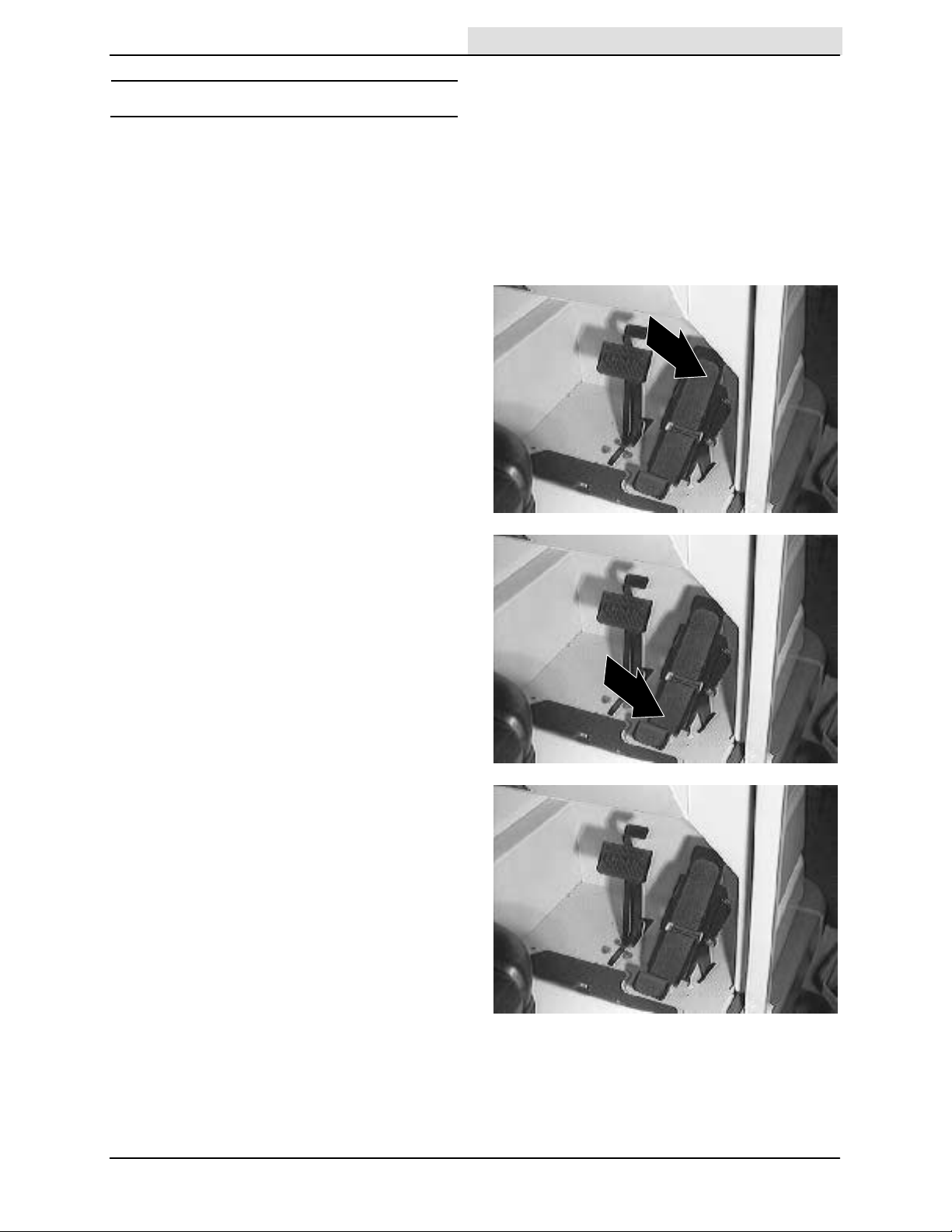
BRAKE PEDAL
The brake pedal stops the machine.
Stop: Take your foot off the directional pedal and
let it return to the neutral position. Step on the
brake pedal.
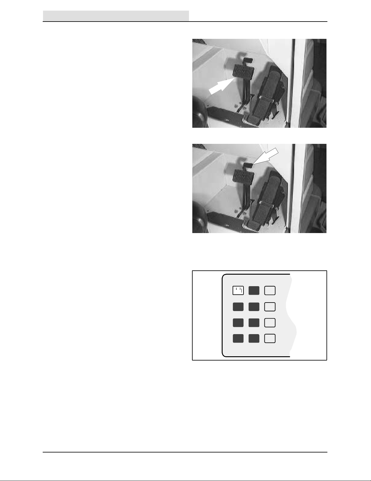
PARKING BRAKE PEDAL
The parking brake pedal sets and releases the
rear wheel brakes.
Set: Press on the brake pedal as far as possible,
then press on the parking brake pedal with the toe
portion of your foot to lock the parking brake pedal
in place.
FOR SAFETY: Before leaving or
servicing machine; stop on level
surface, set parking brake, turn off
machine and remove key.
Release: Press on the brake pedal to unlock the
parking brake pedal.
CHARGING SYSTEM LIGHT
The charging system light comes on when the
alternator is not operating within normal range;
13.5 to 14.5 Volts. Stop operating the machine.
Locate the problem and have it corrected.
10642
12
7400 (GM) 330970 (12-- 03)
ENGINE OIL PRESSURE LIGHT
Home
Find...
Go To..
The engine oil pressure light comes on when the
engine oil pressure falls below 40 kPa (5 psi).
Stop operating the machine. Locate the problem
and have it corrected.
OPERATION
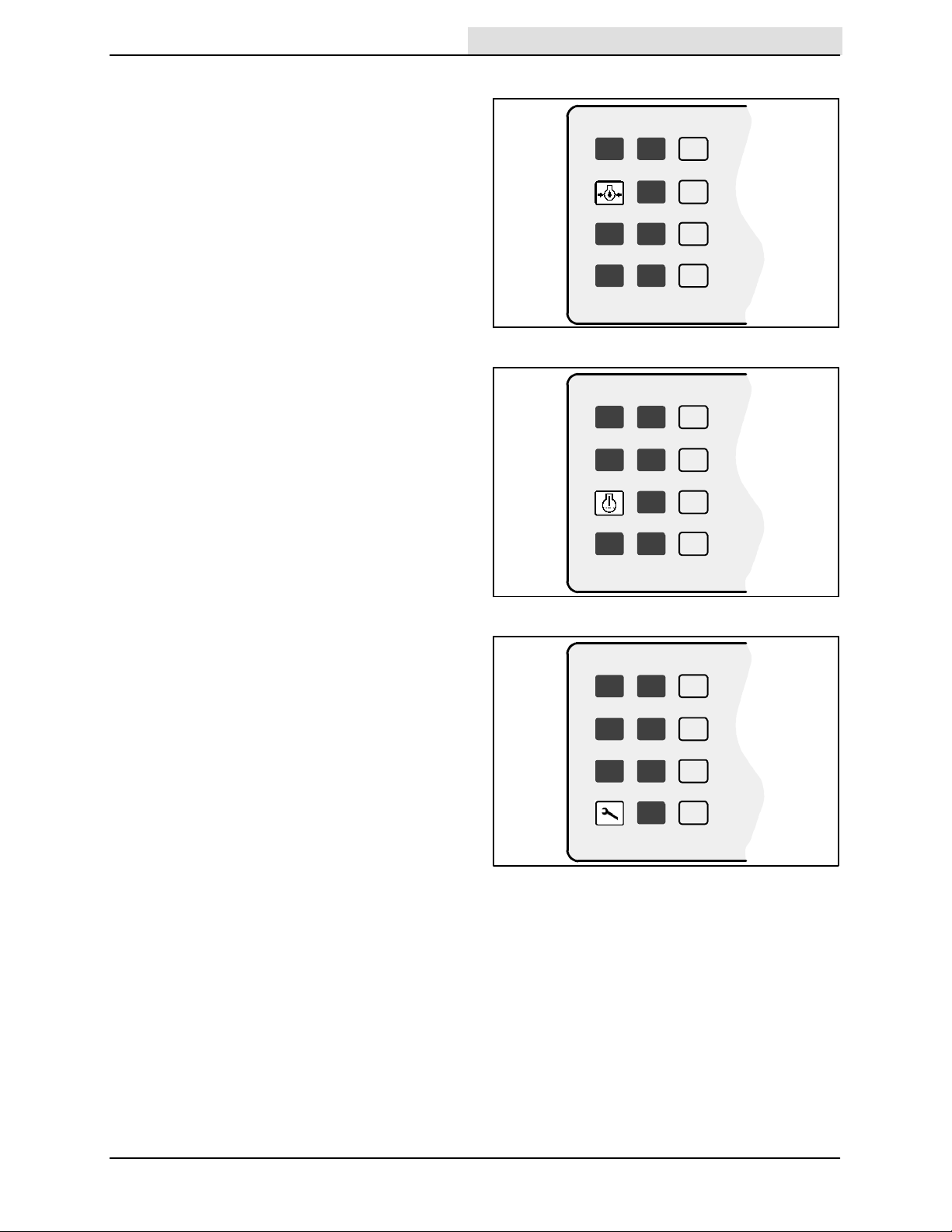
HIGH ENGINE TEMPERATURE LIGHT
The high engine temperature light comes on when
the temperature of the engine coolant is more
than 107_ C (225_ F). If the light comes on, stop
operating the machine. Locate the problem and
have it corrected.
MAINTENANCE MODE LIGHT
The maintenance mode light comes on when the
control panel diagnostic mode is manually
activated. The maintenance mode is for service
personnel use only. To clear the diagnostic mode,
turn the ignition key all the way counter-clockwise.
10643
10644
7400 (GM) 330970 (3-- 07)
10645
13
OPERATION
Home
Find...
Go To..
RECOVERY TANK FULL LIGHT
The recovery tank full light starts blinking when
the recovery tank is full. The light will blink for one
minute and then stay on. Then the scrubbing
operations will shut off.
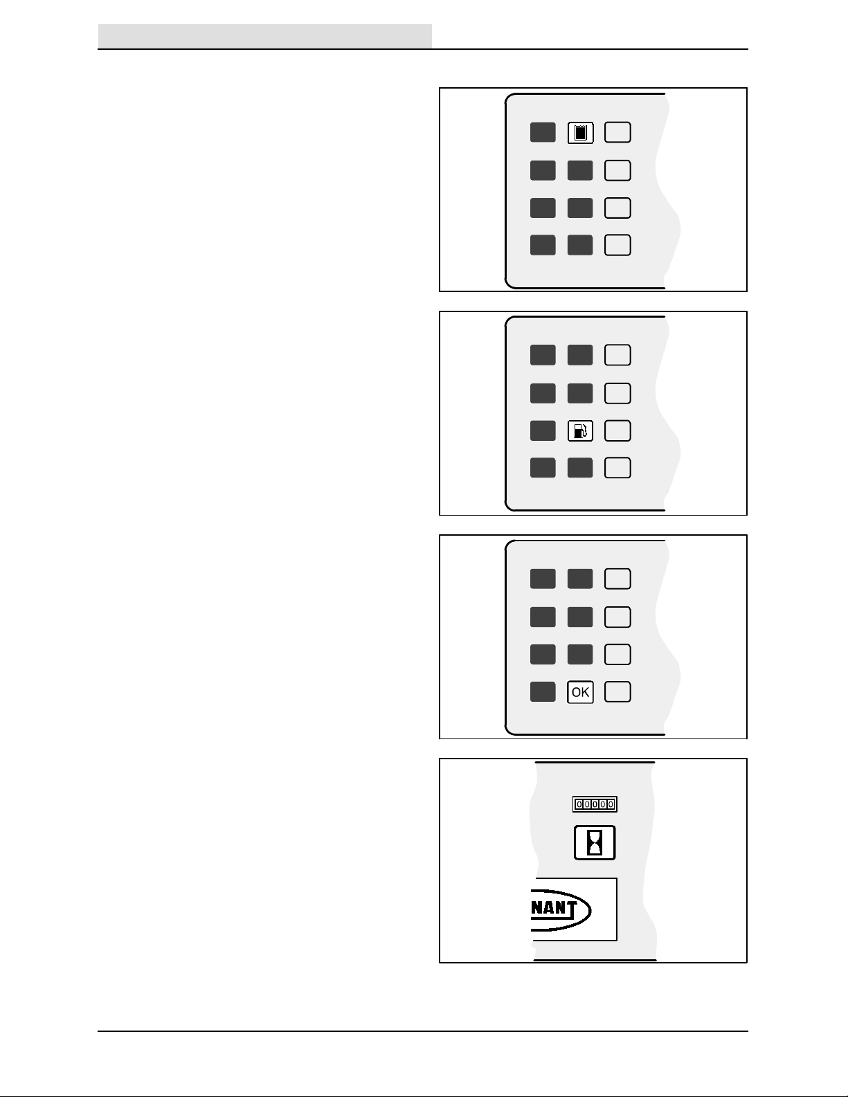
FUEL LEVEL LOW LIGHT
The fuel level low light comes on when the
gasoline or LPG fuel tank is almost empty. The
LPG fuel tank has five minutes of fuel remaining
when the level light comes on.
OK LIGHT
The OK light comes on after the control panel has
run through and passed a self-check every time
the machine is started. The OK light will go out
when the scrub or squeegee switch is activated,
or the engine speed is changed to (Fast).
10886
10888
HOURMETER
The hourmeter records the number of hours the
machine has been operated. The hourmeter
displays the number of hours in tenths of an hour.
Use this information to determine machine
maintenance intervals.
14
10889
07765
7400 (GM) 330970 (12-- 03)
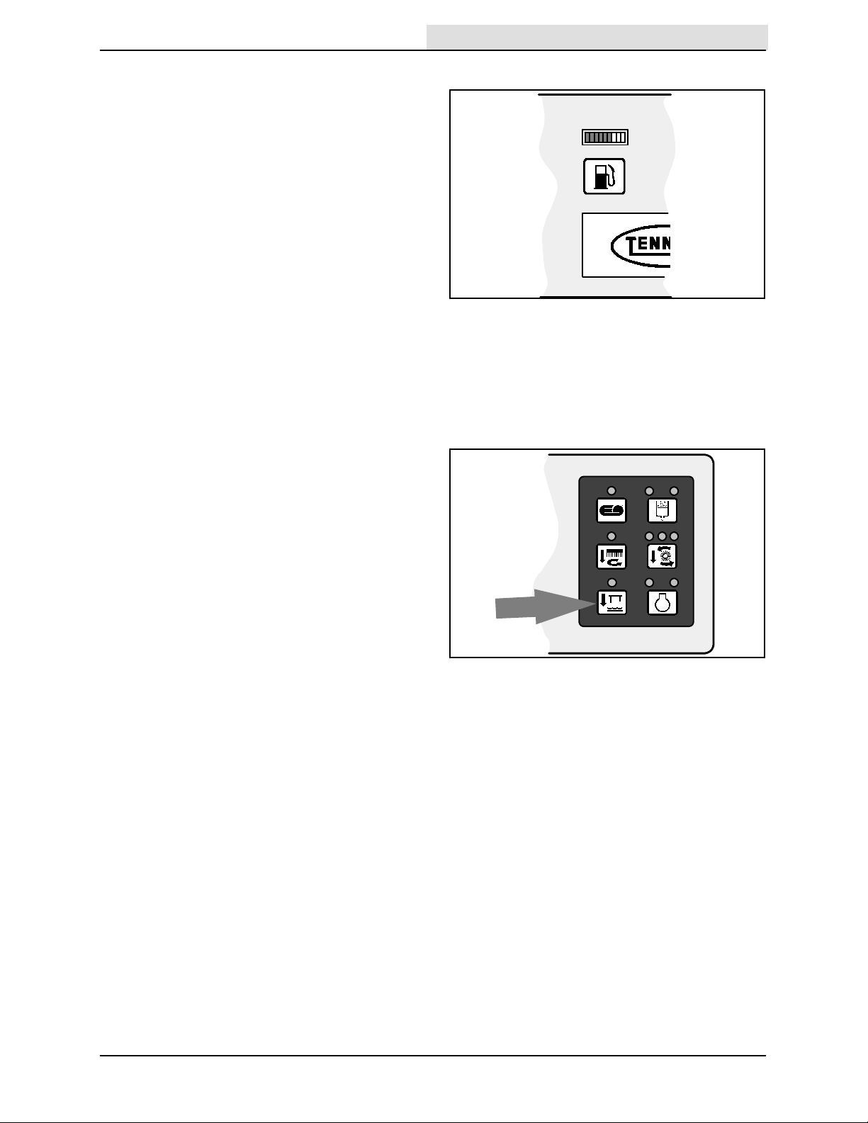
FUEL LEVEL GAUGE
Home
Find...
Go To..
The fuel level gauge indicates how much fuel is in
the fuel tank with a segmented LED light.
Gasoline powered machine: When the tank is full,
all ten of the LED segments are lit. As the fuel
tank empties, the LED segments shut off. The fuel
tank is empty when all ten of the LED segments
have shut off. The fuel level low light comes on
when the last three LED segments are lit.
LPG powered machines: The fuel level gauge is
not operational on LPG machines. However, the
fuel level low light comes on when there is five
minutes of fuel remaining in the tank.
NOTE: Do not use leaded fuels. The use of
leaded fuels will cause permanent damage to the
system’s oxygen sensor and the catalytic
converter.
SQUEEGEE SWITCH
The squeegee switch controls the position of the
rear squeegee, and starts and stops the vacuum
fan. The rear squeegee can be operated
separately, from the scrub brushes, for water
pick-up.
OPERATION
07764
Lower and start: Press the squeegee switch. The
indicator light above the switch will come on.
Raise and stop: Press the squeegee switch. The
indicator light above the switch goes off. There will
be a slight delay before the vacuum fan shuts off.
NOTE: The rear squeegee lowers and the
vacuum fan starts automatically when the
scrubbing operations start.
NOTE: The rear squeegee will raise and the
vacuum fan will stop when the machine travels in
reverse.
NOTE: The rear squeegee will raise and the
vacuum fan will shut off after a short delay when
the scrubbing operations are shut off.
10892
7400 (GM) 330970 (12-- 03)
15
OPERATION
Home
Find...
Go To..
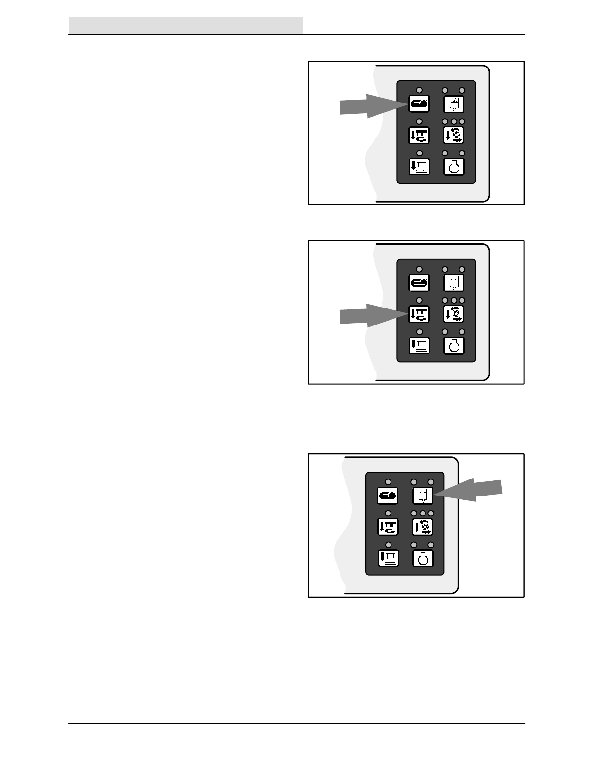
ES SWITCH (OPTION)
The ES switch turns on and off the extended
scrub system. When the machine is started, t he
ES switch will default to the last setting used.
On: Press the ES switch. The indicator light
above the switch will come on.
Off: Press the ES switch. The indicator light
above the switch goes off.
SIDE BRUSH SWITCH (OPTION)
The side brush switch controls the position and
rotation of the side brush, and the solution flow to
the side brush. When the machine is started, the
side brush switch will default to the last setting
used.
10890
Down and on: Press the side brush switch. The
indicator above the switch comes on.
Up and off: Press the side brush switch. The
indicator above the switch goes off.
NOTE: The side brush will lower and start when
the scrubbing operations start. The main scrub
brushes have to be on for the side brush to
operate.
DETERGENT FLOW SWITCH (OPTION)
The detergent flow switch starts and stops the
detergent pump for the optional ES system. When
the machine is started, the detergent flow switch
will default to the last setting used.
Start at one-half flow: Press the detergent flow
switch. The left indicator light above the switch will
come on.
Increase to full flow: Press and hold the detergent
flow switch until both indicator lights above the
switch come on.
10891
Stop: Press the detergent flow switch. Both
indicator lights are off.
16
10893
7400 (GM) 330970 (9-- 04)
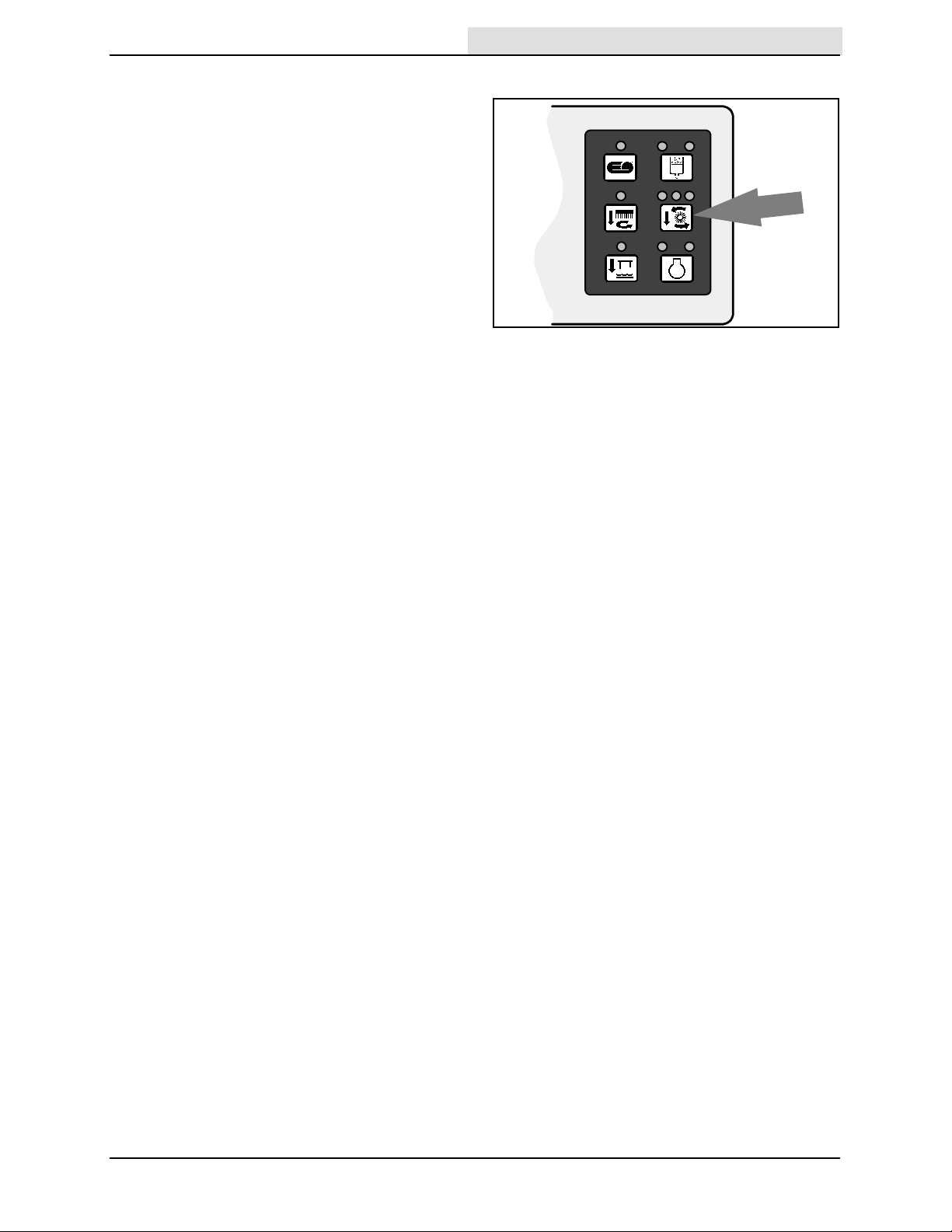
SCRUB SWITCH
Home
Find...
Go To..
The scrub switch controls the scrubbing
operations. The scrub switch also sets the scrub
brush pressure.
The scrubbing operations include the following.
The scrub head lowers and the brushes turn on.
The rear squeegee will lower and the vacuum fan
will start. The solution system will start, if the
solution flow switch is on. The FaST system or
optional ES system and detergent pump will start,
if the switches are on. The optional side brush will
lower and turn on, if the side brush switch is on.
The engine speed will change to (Fast).
NOTE: The brush pressure setting, the FaST
system, the detergent flow rate, the side brush,
and the ES system will default to the last setting
used when the scrubbing operations are started
again.
Start: Press the scrub switch. The indicator light
above the switch will come on.
OPERATION
10894
Stop: Press the scrub switch. The indicator light
above the switch goes off.
Scrub brush pressure: Press and hold the scrub
switch. The brush pressure will scroll through the
three settings. The pressure setting selected
when the switch is released, will be the new
default brush pressure setting.
The brush pressure has three positions. Under
normal conditions, the brush pressure should be
set in the minimum setting. Under heavy grime
conditions, the brush pressure should be set in
the maximum setting. Travel speed and floor
conditions will affect the scrubbing performance.
NOTE: The scrub head and squeegee will raise
when the machine travels in reverse.
7400 (GM) 330970 (3-- 05)
17
OPERATION
Home
Find...
Go To..
ENGINE SPEED SWITCH
The engine speed switch controls the engine
governed speed. The two indicator lights above
the switch show the engine speed; idle or fast.
Idle: The engine will automatically start in idle
speed. To return the engine to idle from the (Fast)
engine speed, press the engine speed switch until
the left indicator light comes on. The scrubbing
operations will turn off automatically.
Fast: Press the engine speed switch and the right
indicator light comes on. This speed is for
transporting and scrubbing.
NOTE: The engine will automatically operate in
the (Fast) speed when the scrubbing operations
are started.
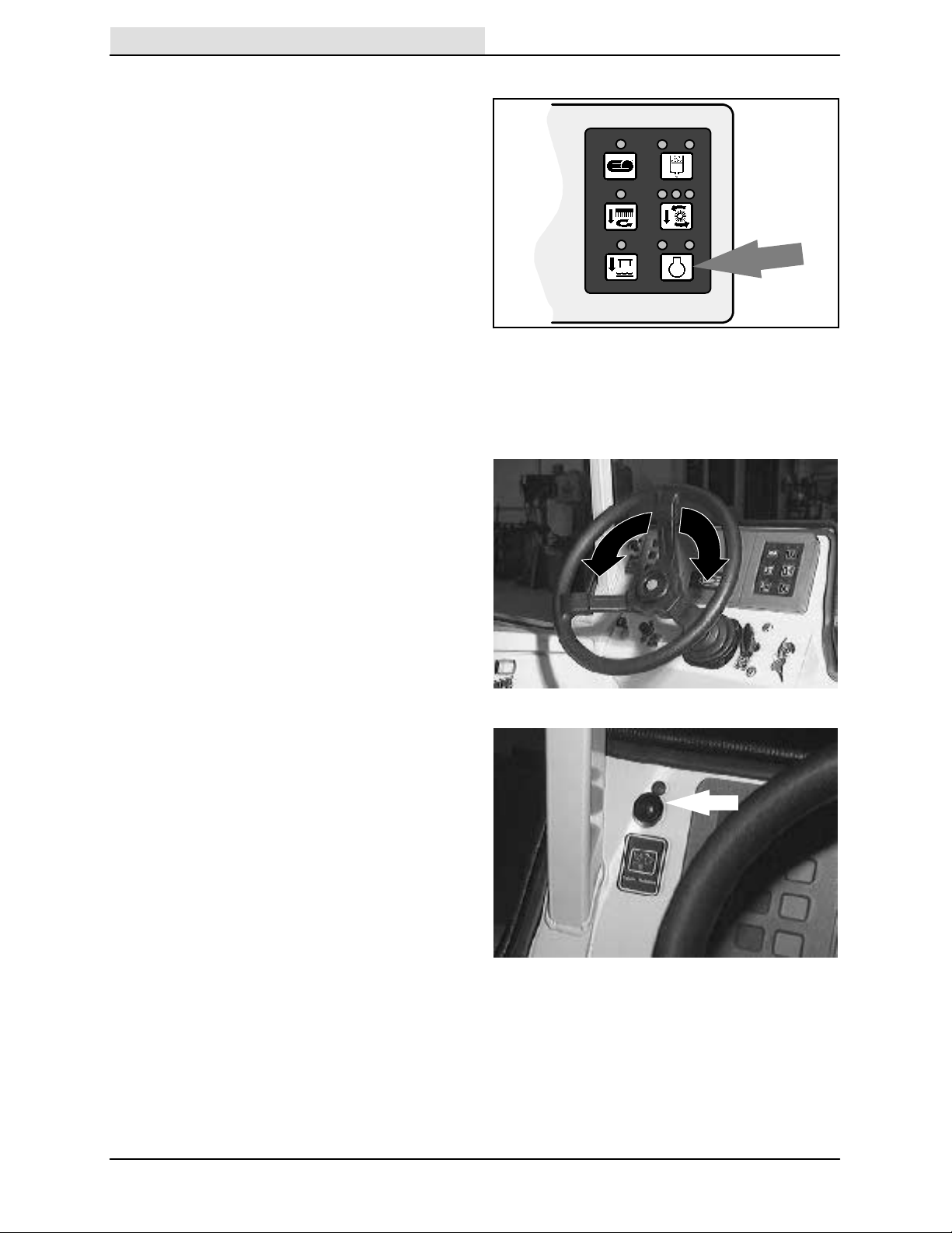
STEERING WHEEL
The steering wheel controls the machine’s
direction. The machine is very responsive to the
steering wheel movements.
10895
Left: Turn the steering wheel to the left.
Right: Turn the steering wheel to the right.
COVER RELEASE KNOB
The cover release knob releases the machine
front cover latch.
To release: Pull out and hold the cover release
knob, then pull open the machine cover.
18
7400 (GM) 330970 (12-- 03)
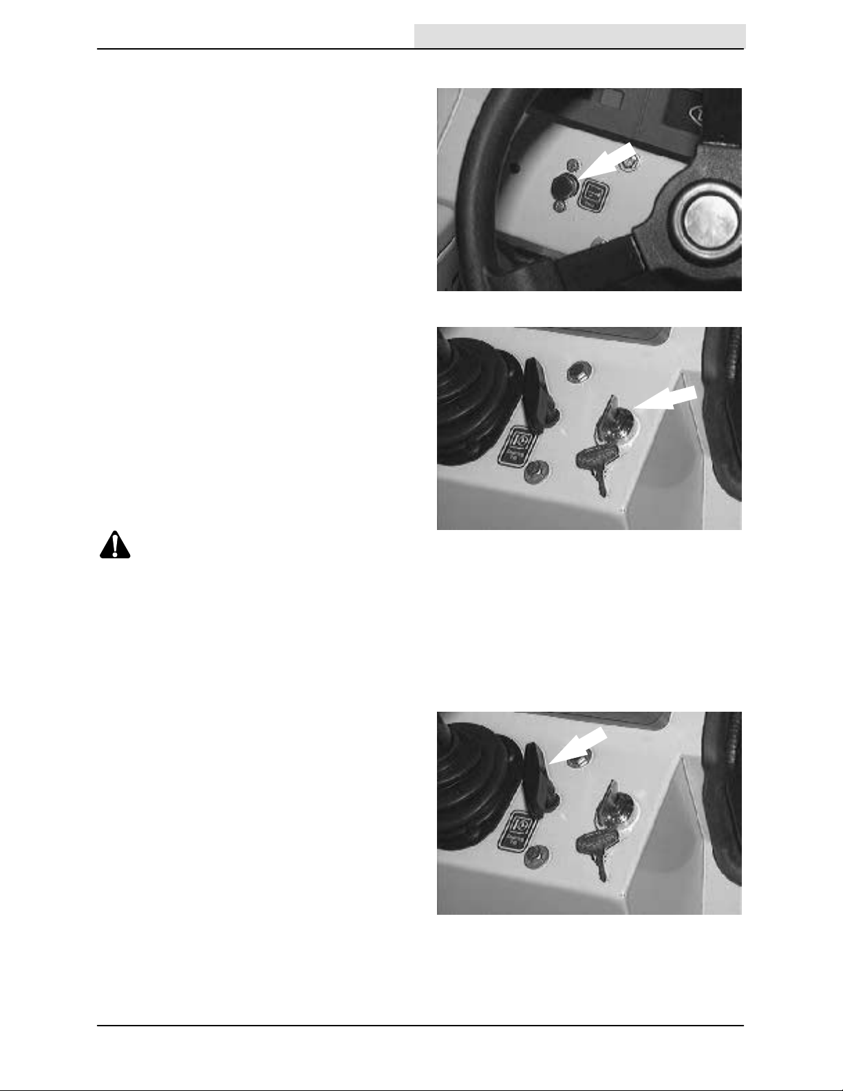
HORN BUTTON
Home
Find...
Go To..
The horn button operates the horn.
Sound: Press the button.
IGNITION SWITCH
The ignition switch starts and stops the engine
with a key. The operating lights will automatically
turn on when the machine is started.
FOR SAFETY: When starting machine,
keep foot on brake and directional pedal
in neutral.
OPERATION
Start: Turn the key all the way clockwise.
Release the key as soon as the engine starts.
Stop: Turn the key counter-clockwise.
CAUTION: LPG engine will run for a few
seconds after key is turned off. Apply
parking brake before leaving machine.
NOTE: To protect the engine’s emission
components on LPG powered machines, the
engine will continue to operate for a few seconds
after the ignition switch is turned off.
STEERING COLUMN TILT HANDLE
The steering wheel tilt handle adjusts the angle of
the steering wheel.
Adjust: Pull out the tilt handle, move the wheel up
or down, and release the tilt handle.
7400 (GM) 330970 (12-- 05)
19
OPERATION
Home
Find...
Go To..
CHECK ENGINE LIGHT
The check engine light comes on if the engine
control system detects a fault during machine
operation.
If the check engine light comes on while operating
the machine, contact a TENNANT service
representative.
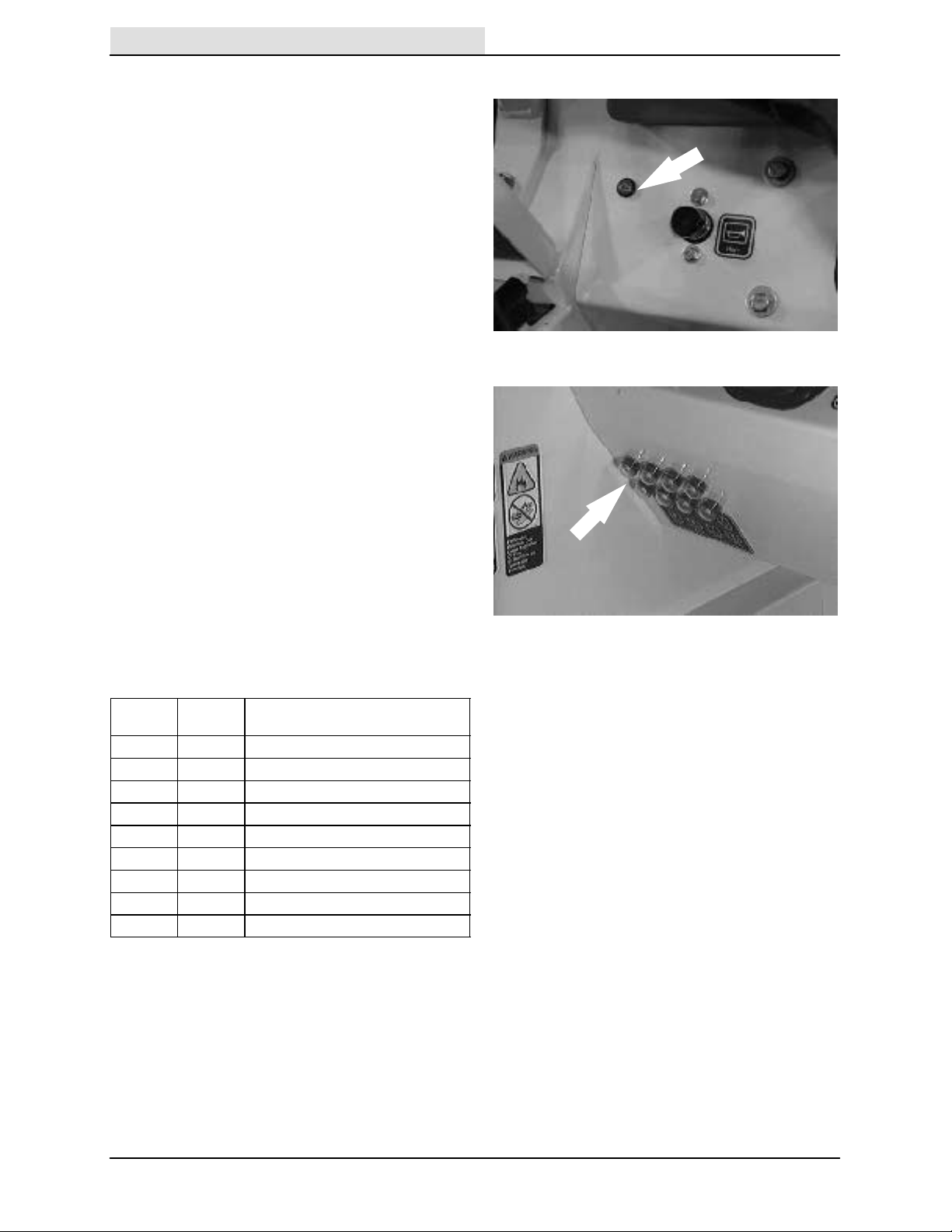
CIRCUIT BREAKERS
The circuit breakers are resetable electrical circuit
protection devices. Their design stops the flow of
current in the event of a circuit overload. Once a
circuit breaker is tripped, it must be reset
manually. Press the reset button after the breaker
has cooled down.
If the overload that caused the circuit breaker to
trip is still there, the circuit breaker will continue to
stop current flow until the problem is corrected.
The circuit breakers are located in the operator
compartment.
The chart lists the circuit breakers and the
electrical components they protect.
Circuit
Breaker
CB-1 15 A Ignition
CB-2 15 A ES (option)
CB-3 15 A Operating lights
CB-4 15 A Back-up alarm (option)
CB-5 15 A Horn
CB-6 5A Instrument panel (007000--007548)
CB-6 15 A Instrument panel (007549-- )
CB-7 15 A Scrubbing
CB-8 15 A Side brush (option)
Rating Circuit Protected
20
7400 (GM) 330970 (3-- 05)
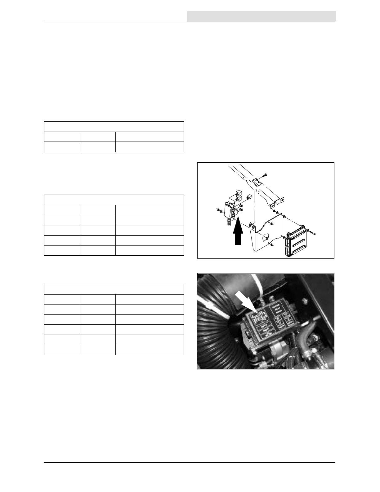
FUSES
Home
Find...
Go To..
The fuses are one-time protection devices
designed to stop the flow of current in the event of
a circuit overload.
NOTE: Always replace the fuse with a fuse of the
same amperage.
The main harness fuse is located near the relays
under the front hood. Access the fuse by opening
the front hood.
Main Harness Fuse
Fuse Rating Circuit Protected
FU-1 15 A Circuit board
The engine harness fuses are located near the
engine under the engine cover. Access the fuses
by opening the engine cover.
OPERATION
Engine Harness Fuses (S/N 007000--007078)
Fuse Rating Circuit Protected
FU-1 5A Key switch
FU-2 20 A Main power
FU-3 15 A Auxilary power
FU-4 15 A Fuel pump
Engine Harness Fuses (S/N 007079-- )
Fuse Rating Circuit Protected
FU-1 5A Key switch
FU-2 20 A Main power
FU-3 15 A Auxilary power
FU-4 15 A Fuel pump
FU-5 50 A Alternator
7400 (GM) 330970 (9-- 04)
21

OPERATION
Home
Find...
Go To..
SOLUTION FLOW SWITCH (WITHOUT FaST)
The solution flow switch controls the flow of
solution to the floor. The solution flow switch is
only on machines without the FaST system.
Start (1): Place the solution flow switch in the
middle position. Use this flow rate for smooth
floors and light dirt.
Increase (2): Press the right of the solution flow
switch. Use this flow rate for rough floors and
heavy or compacted dirt.
Stop (0): Press the left of the solution flow switch.
NOTE: The solution flow starts, if the solution
flow switch is on, when the scrubbing operations
start.
SOLUTION FLOW SWITCH (FaST)
The FaST solution flow switch enables the FaST
(Foam Scrubbing Technology) system. When the
FaST system is enabled, it is turned on and off
with the FaST switch. Disable the FaST system
before using the machine for conventional
scrubbing.
For machines with the FaST system, the FaST
solution flow switch controls the flow of solution to
the floor.
Start (1): Place the FaST solution flow switch in
the middle position. Use this flow rate for smooth
floors and light dirt.
Increase (2): Press the top of the FaST solution
flow switch. Use this flow rate for rough floors and
heavy or compacted dirt.
Stop (0): Press the bottom of the FaST solution
flow switch.
FaST SWITCH
The FaST switch enables the FaST (Foam
Scrubbing Technology) system. When the FaST
system is enabled, it is turned on and off with the
FaST switch. Disable the FaST system before
using the machine for conventional scrubbing.
Disable FaST for conventional scrubbing: Press
the bottom of switch to the FaST system off
position.
Enable the FaST system: Press the top of switch
to the FaST system on position.
NOTE: The FaST system will not start until the
directional pedal is pressed.
22
7400 (GM) 330970 (3-- 05)
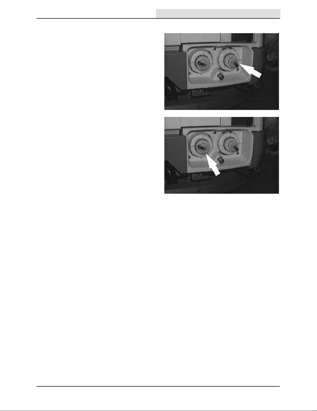
SOLUTION TANK DRAIN HOSE
Home
Find...
Go To..
The solution tank drain hose is used to drain the
solution tank. Drain the solution tank by removing
the drain hose cap from the tank access cap. Pull
out the solution tank hose and remove the drain
hose end cap.
RECOVERY TANK DRAIN HOSE
The recovery tank drain hose is used to drain the
recovery tank. Drain the recovery tank by
removing the drain hose cap from the tank access
cap. Pull out the recovery tank hose and remove
the drain hose end cap.
OPERATION
7400 (GM) 330970 (9-- 04)
23
OPERATION
Home
Find...
Go To..
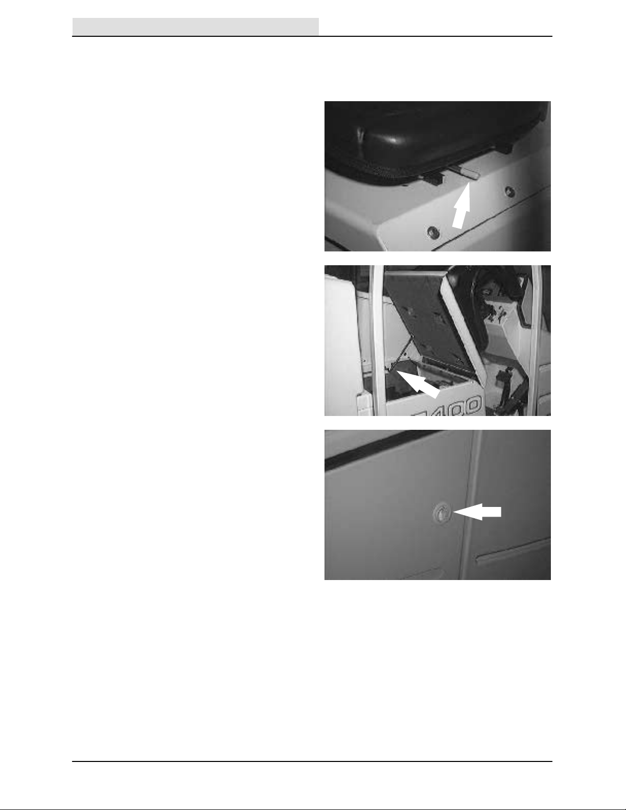
OPERATOR SEAT
The operator seat is a fixed back style with a
forward-backward position adjustment.
Adjust: Pull the lever, slide the seat backward or
forward to the desired position and release the
lever.
Lift: Pull up on the seat mounting plate until the
seat mount locks up.
Lower: Pull on the release lever and lower the
seat mounting plate.
LATCHES
The side doors, engine cover, debris tray, back
grille, and solution tank covers are secured with
latches.
Open the brush side doors: Push down on the
door latch.
Open the engine side door: Pull out on the door
latch.
Open the engine cover: Open the engine side
door and pull on the latch release.
Release the debris tray: Pull down on the latch
handle.
Open the back grille: Pull up on the latches.
Open the solution tank covers: Pull up on the
cover latch.
24
7400 (GM) 330970 (3-- 05)

HOW THE MACHINE WORKS
Home
Find...
Go To..
The steering wheel controls the direction of
machine travel. The directional pedal controls the
speed and forward/reverse direction. The brake
pedal slows and stops the machine.
Water and detergent, from the solution tank, flow
to the floor through a solution valve to the scrub
brushes. The brushes scrub the floor. As the
machine travels forward the squeegee wipes the
dirty solution off the floor, which is then picked up
and drawn into the recovery tank.
When using the ES mode, the solution in the
recovery tank is filtered and returned to the
solution tank to be reused.
When scrubbing is finished, drain and clean the
recovery tank. If using the ES system, drain and
clean the solution tank, clean the solution outlet
filter, and clean the ES filter.
OPERATION
7400 (GM) 330970 (9-- 04)
25
OPERATION
Home
Find...
Go To..
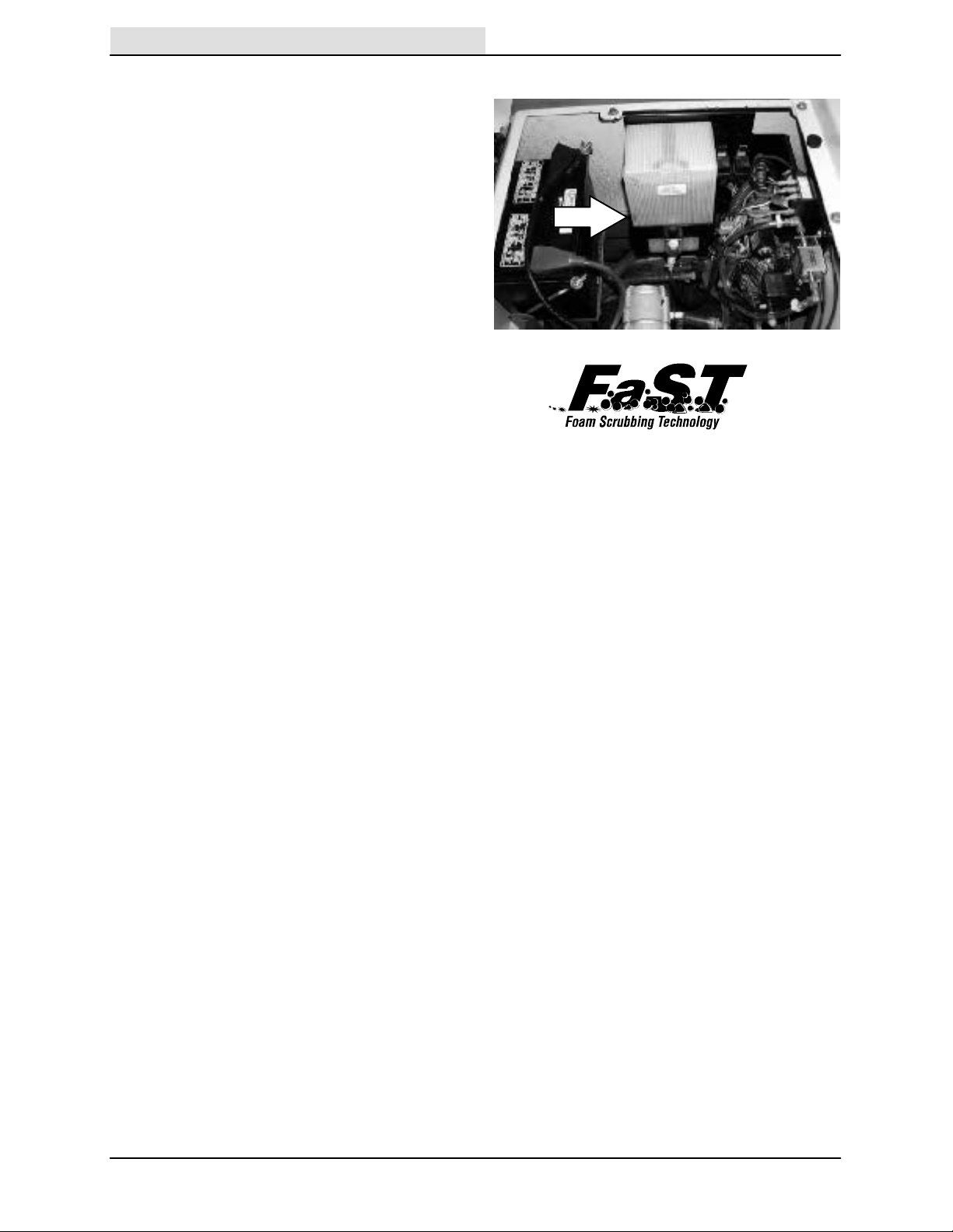
FaST SCRUBBING SYSTEM
Unlike conventional scrubbing, the FaST (Foam
Scrubbing Technology) system operates by
injecting the FaST PAK concentrate agent into the
system with a small amount of water and
compressed air. This mixture creates a large
volume of expanded wet foam.
The expanded foam mixture is then dispersed
onto the floor while the machine is scrubbing.
When the squeegee picks up the mixture, the
patented foaming agent has collapsed and is
recovered into the recovery tank.
The FaST system can be used with all double
scrubbing and heavy duty scrubbing applications.
Using the FaST system can increase
productivity by 30% by reducing your dump/fill
cycle. It will also reduce chemical usage and
storage space. One FaST PAK of concentrated
agent can scrub up to 1 million sq. ft.
The safe scrubbing alternative
NOTE: Do not enable the FaST system with
conventional cleaning detergents in the solution
tank. Drain, rinse and refill the solution tank with
clear cool water only before operating the FaST
system. Conventional cleaning detergents/
restorers may cause failure to the FaST solution
system.
NOTE: Storage or transporting machines
equipped with FaST in freezing temperatures
requires special procedures. Check with a
TENNANT representative for advice.
26
7400 (GM) 330970 (3-- 07)
 Loading...