

Tennant 6500D User Manual

6500D
Home
Find...
Go To..
Operator Manual
330290
Rev. 06
*330290*

This manual is furnished with each new TENNANT Model 6500D. It provides necessary operating and
Home
Find...
Go To..
preventive maintenance instructions. Read this manual completely and understand the machine before
operating or servicing it.
This machine will provide excellent service. However, the best results will be obtained at minimum
costs if:
D The machine is operated with reasonable care.
D The machine is maintained regularly -- per the maintenance instructions provided.
D The machine is maintained with TENNANT supplied or approved parts.
Manual Number -- 330290
Revision: 06
Published: 9--02
CALIFORNIA PROPOSITION 65 WARNING:
Engine exhaust from this product contains chemicals known to the State of
California to cause cancer, birth defects, or other reproductive harm.
Copyright E 1998, 1999, 2000, 2001, 2002 TENNANT, Printed in U.S.A.

CONTENTS
Home
Find...
Go To..
CONTENTS
SAFETY PRECAUTIONS 3.................
OPERATION 6............................
OPERATOR RESPONSIBILITY 6.........
MACHINE COMPONENTS 9.............
CONTROL PANEL SYMBOLS 10..........
CONTROLS AND INSTRUMENTS 12......
OPERATION OF CONTROLS 14..........
DIRECTIONAL PEDAL 14..............
BRAKE PEDAL 15....................
PARKING BRAKE LEVER 15...........
HORN BUTTON 15....................
MAIN BRUSH AND SIDE BRUSH
LEVER 16.........................
HOPPER DOOR LEVER 17............
HOPPER LIFT LEVER 18..............
MAIN BRUSH POSITION LEVER 19....
MAIN BRUSH DOWN PRESSURE
KNOB 21..........................
MAIN BRUSH ADJUSTMENT KNOB 22..
TURN SIGNAL SWITCH (OPT ION) 23...
HOPPER TEMPERATURE LIGHT --
THERMO SENTRYt 24............
ENGINE WATER TEMPERATURE
LIGHT 24..........................
ENGINE OIL PRESSURE LIGHT 25.....
CHARGING SYSTEM LIGHT 25........
HOPPER DOOR LIGHT 26.............
CLOGGED FILTER LIGHT 26..........
CLOGGED FILTER LIGHT (OPTION) 26.
GLOW PLUG LIGHT 27................
HOURMETER 27.....................
FUEL LEVEL GAUGE 27...............
HAZARD LIGHT SWITCH (OPTION) 28..
OPERATING LIGHTS SWITCH 28......
OPERATING/HAZARD LIGHTS
SWITCH 28........................
VACUUM FAN SWITCH 29.............
FILTER SHAKER SWITCH 29..........
V ACUUM FAN/FILTER SHAKER
SWITCH 29........................
ENGINE SPEED SWITCH 30...........
STEERING WHEEL 32................
STEERING COLUMN TILT LEVER 32...
IGNITION SWITCH 33.................
SIDE BRUSH POSITION LEVER 34.....
SIDE BRUSH DOWN PRESSURE
KNOB 35..........................
Page
Page
CIRCUIT BREAKERS 36...............
FUSES 36............................
CIRCUIT BREAKERS 37...............
LATCHES 38.........................
HOPPER SUPPORT BAR 38...........
OPERATOR SEAT 39..................
HEATER KNOB (OPTION) 39..........
AIR CONDITIONING SWITCH
(OPTION) 39......................
WINDSHIELD WIPER SWITCH
(OPTION) 40......................
DOME LIGHT SWITCH (OPTION) 40....
HEATER SWITCH (OPT ION) 40........
PRESSURIZER SWITCH (OPTION) 40..
HOW THE MACHINE WORKS 41..........
PRE-OPERATION CHECKLIST 41.........
STARTING THE MACHINE 43.............
SWEEPING AND BRUSH INFORMATION 45
SWEEPING 46..........................
STOP SWEEPING 48....................
EMPTYING THE HOPPER 50.............
STOP THE MACHINE 52.................
POST-OPERATION CHECKLIST 53........
ENGAGING HOPPER SUPPORT BAR 54..
DISENGAGING HOPPER SUPPORT BAR 55
OPERATION ON INCLINES 56............
OPTIONS 57............................
VACUUM WAND 57...................
BLOWER WAND 63...................
HE ATER VA LV E 64....................
MACHINE TROUBLESHOOTING 65.......
MAINTENANCE 66.........................
MAINTENANCE CHART 66...............
LUBRICATION 68........................
ENGINE 68...........................
REAR WHEEL SUPPORT 68...........
HOPPER BEARINGS 69...............
FRONT WHEEL BEARINGS 69.........
HYDRAULICS 70........................
HYDRAULIC FLUID RESERVOIR 70....
HYDRAULIC FLUID 70................
HYDRAULIC HOSES 71...............
PROPELLING MOTOR 71..............
ENGINE 72.............................
COOLING SYSTEM 72................
AIR FIL TER INDICAT OR 73............
AIR FILTER 73........................
FUEL FILTER 74......................
FUEL PIPES 74.......................
PRIMING FUEL SYSTEM 74...........
BATTERY 75............................
6500D 330290 (9-- 01)
1

CONTENTS
Home
Find...
Go To..
BELTS AND CHAINS 75..................
ENGINE FAN BELT 75.................
STATIC DRAG CHAIN 75..............
DEBRIS HOPPER 76.....................
HOPPER DUST FILTER 76.............
TO REPLACE HOPPER DUST FILTER 77
THERMO SENTRYt 79..................
BRUSHES 80............................
MAIN BRUSH 80......................
TO REPLACE MAIN BRUSH 81......
TO CHECK AND ADJUST MAIN
BRUSH PATTERN 83...........
SIDE BRUSH 87......................
TO REPLACE SIDE BRUSH 88......
SIDE BRUSH GUARD 88...........
SKIRTS AND SEALS 89..................
HOPPER LIP SKIRTS 89...............
HOPPER SIDE SKIRT 89..............
BRUSH DOOR SKIRTS 89.............
REAR SKIRTS 90.....................
SIDE BRUSH DUST CONTROL SKIRTS
(OPTION) 90......................
BRUSH DOOR SEALS 90..............
HOPPER SEALS 91...................
HOPPER INSPECTION DOOR SEAL 91.
HOPPER DOOR SEALS 91............
HOPPER COVER SEAL
(Metal Hoppers) 92.................
HOPPER DUST SEAL
(Metal Hoppers) 92.................
HOPPER VACUUM FAN SEAL
(Metal Hoppers) 92.................
HOPPER FILTER SEALS 92............
BRAKES AND TIRES 93..................
SERVICE BRAKES 93.................
PARKING BRAKE 93..................
REAR WHEEL 93.....................
PUSHING, TOWING, AND TRANSPORTING
THE MACHINE 94.....................
PUSHING OR TOWING THE MACHINE 94
TRANSPORTING THE MACHINE 94....
MACHINE JACKING 97...................
STORING MACHINE 97..................
SPECIFICATIONS 98.......................
GENERAL MACHINE
DIMENSIONS/CAPACITIES 98.........
GENERAL MACHINE PERFORMANCE 98..
POWER TYPE 99........................
STEERING 99...........................
HYDRAULIC SYSTEM 99.................
BRAKING SYSTEM 99...................
TIRES 99...............................
MACHINE DIMENSIONS 100.................
INDEX 100.................................
Page
2
6500D 330290 (9-- 02)
SAFETY PRECAUTIONS
Home
Find...
Go To..
SAFETY PRECAUTIONS
The following precautions are used throughout
this manual as indicated in their description:
WARNING: To warn of hazards or
unsafe practices which could result in
severe personal injury or death.
FOR SAFETY: To identify actions which
must be followed for safe operation of
equipment.
The machine is suited to sweep disposable
debris. Do not use the machine other than
described in this Operator Manual. The machine
is not designed for use on public roads.
The following information signals potentially
dangerous conditions to the operator or
equipment:
WARNING: Engine emits toxic gases.
Severe respiratory damage or
asphyxiation can result. Provide
adequate ventilation. Consult with your
regulatory authorities for exposure
limits. Keep engine properly tuned.
WARNING: Raised hopper may fall.
Engage hopper support bar.
WARNING: Lift arm pinch point. Stay
clear of hopper lift arms.
WARNING: Moving belt and fan. Keep
away.
FOR SAFETY:
1. Do not operate machine:
-- Unless trained and authorized.
-- Unless operator manual is read and
understood.
-- If it is not in proper operating
condition.
-- In flammable or explosive areas unless
designed for use in those areas.
-- In areas with possible falling objects
unless equipped with overhead guard.
3. When starting machine:
-- Keep foot on brake and directional
pedal in neutral.
4. When using machine:
-- Use brakes to stop machine.
-- Go slow on inclines and slippery
surfaces.
-- Use care when reversing machine.
-- Move machine with care when hopper
is raised.
-- Make sure adequate clearance is
available before raising hopper.
-- Do not carry passengers on machine.
-- Always follow safety and traffic rules.
-- Report machine damage or faulty
operation immediately.
5. Before leaving or servicing machine:
-- Stop on level surface.
-- Set parking brake.
-- Turn off machine and remove key.
6. When servicing machine:
-- Avoid moving parts. Do not wear loose
jackets, shirts, or sleeves.
-- Block machine tires before jacking
machine up.
-- Jack machine up at designated
locations only. Block machine up with
jack stands.
-- Use hoist or jack that will support the
weight of the machine.
-- Wear eye and ear protection when
using pressurized air or water.
-- Disconnect battery connections before
working on machine.
-- Avoid contact with battery acid.
-- Avoid contact with hot engine coolant.
-- Allow engine to cool.
-- Keep flames and sparks away from
fuel system service area. Keep area
well ventilated.
-- Use cardboard to locate leaking
hydraulic fluid under pressure.
-- Use TENNANT supplied or approved
replacement parts.
2. Before starting machine:
-- Check for fuel, oil, and liquid leaks.
-- Keep sparks and open flame away
from refueling area.
-- Make sure all safety devices are in
place and operate properly.
-- Check brakes and steering for proper
operation.
6500D 330290 (9-- 02)
3

SAFETY PRECAUTIONS
Home
Find...
Go To..
7. When loading/unloading machine
onto/off truck or trailer:
-- Turn off machine.
-- Use truck or trailer that will support
the weight of the machine.
-- Use winch. Do not drive the machine
onto/off the truck or trailer unless the
load height is 380 mm (15 in) or less
from the ground.
-- Set parking brake after machine is
loaded.
-- Block machine tires.
-- Tie machine down to truck or trailer.
4
6500D 330290 (9-- 02)
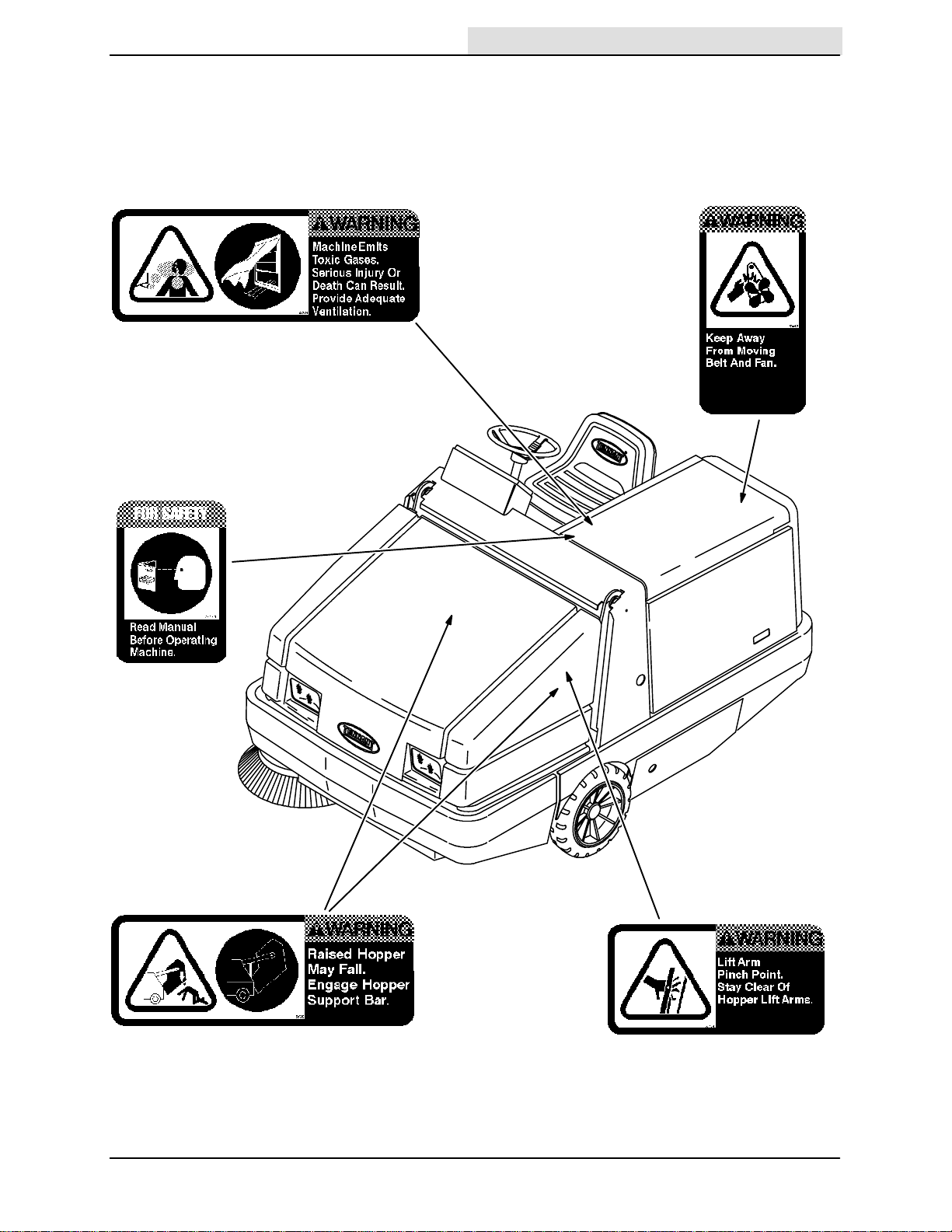
The following safety labels are mounted on the
Home
Find...
Go To..
machine in the locations indicated. If these or any
label becomes damaged or illegible, install a new
label in its place.
SAFETY PRECAUTIONS
EMISSIONS LABEL -- LOCATED ON THE SIDE
PANEL OF THE OPERATOR COMPARTMENT.
FOR SAFETY LABEL -- LOCATED ON
THE SIDE PANEL OF THE OPERATOR
COMPARTMENT.
ENGINE FAN AND BELT LABEL -LOCATED ON THE RADIATOR SHROUD.
HOPPER SUPPORT BAR LABEL -- LOCATED
ON THE HOPPER SUPPORT BAR AND ON
BOTH HOPPER LIFT ARMS.
6500D 330290 (5-- 98)
07748
HOPPER LIFT ARMS LABEL -- LOCATED
ON BOTH HOPPER LIFT ARMS.
5
OPERATION
Home
Find...
Go To..
OPERATOR RESPONSIBILITY
- The operator’s responsibility is to take care
of the daily maintenance and checkups of
the machine to keep it in good working
condition. The operator must inform the
service mechanic or supervisor when the
required maintenance intervals occur as
stated in the MAINTENANCE section of this
manual.
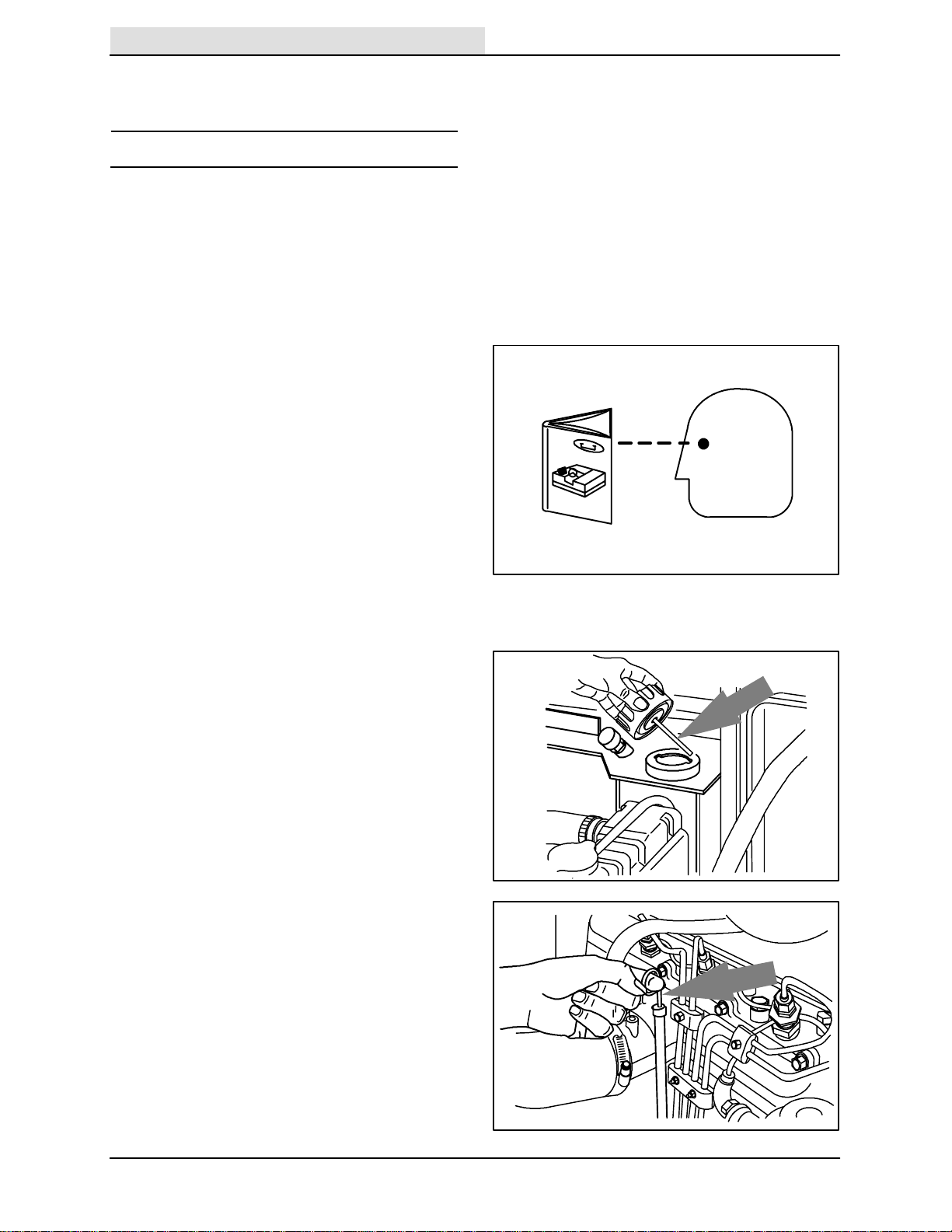
- Read this manual carefully before operating
this machine.
FOR SAFETY: Do not operate machine,
unless operation manual is read and
understood.
OPERATION
- Check the machine for shipping damage.
Check to make sure machine is complete
per shipping instructions.
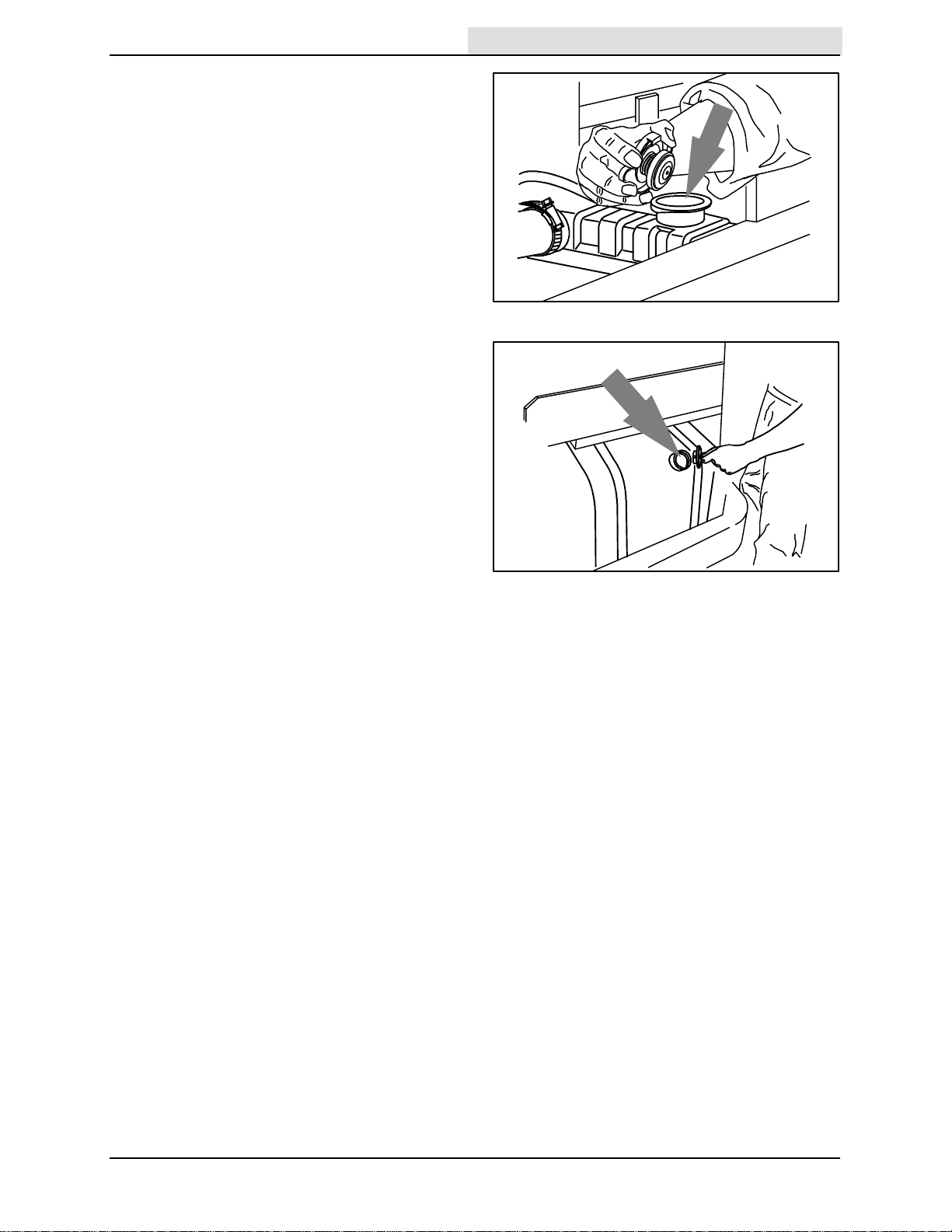
- Check the hydraulic fluid level in the
hydraulic reservoir.
- Check the engine oil level.
07324
07750
08431
6
6500D 330290 (5-- 98)
- Check the radiator coolant level.
Home
Find...
Go To..
FOR SAFETY: When servicing machine,
avoid contact with hot engine coolant.
- Fill the fuel tank.
FOR SAFETY: When servicing machine,
keep flames and sparks away from fuel
system service area. Keep area well
ventilated.
OPERATION
07752
07753
6500D 330290 (9-- 01)
7

OPERATION
Home
Find...
Go To..
- LPG powered machines: Install the LPG fuel
tank on the machine. See CHANGING AN
LPG FUEL TANK.
- After the first 50 hours of operation, follow
the recommended procedures stated in the
MAINTENANCE CHART.
- Keep your machine regularly maintained by
following the maintenance information in this
manual. We recommend taking advantage
of a regularly scheduled service contract
from your TENNANT representative.
- Order parts and supplies directly from your
authorized TENNANT representative. Use
the parts manual provided when ordering
parts.
8
6500D 330290 (9-- 01)
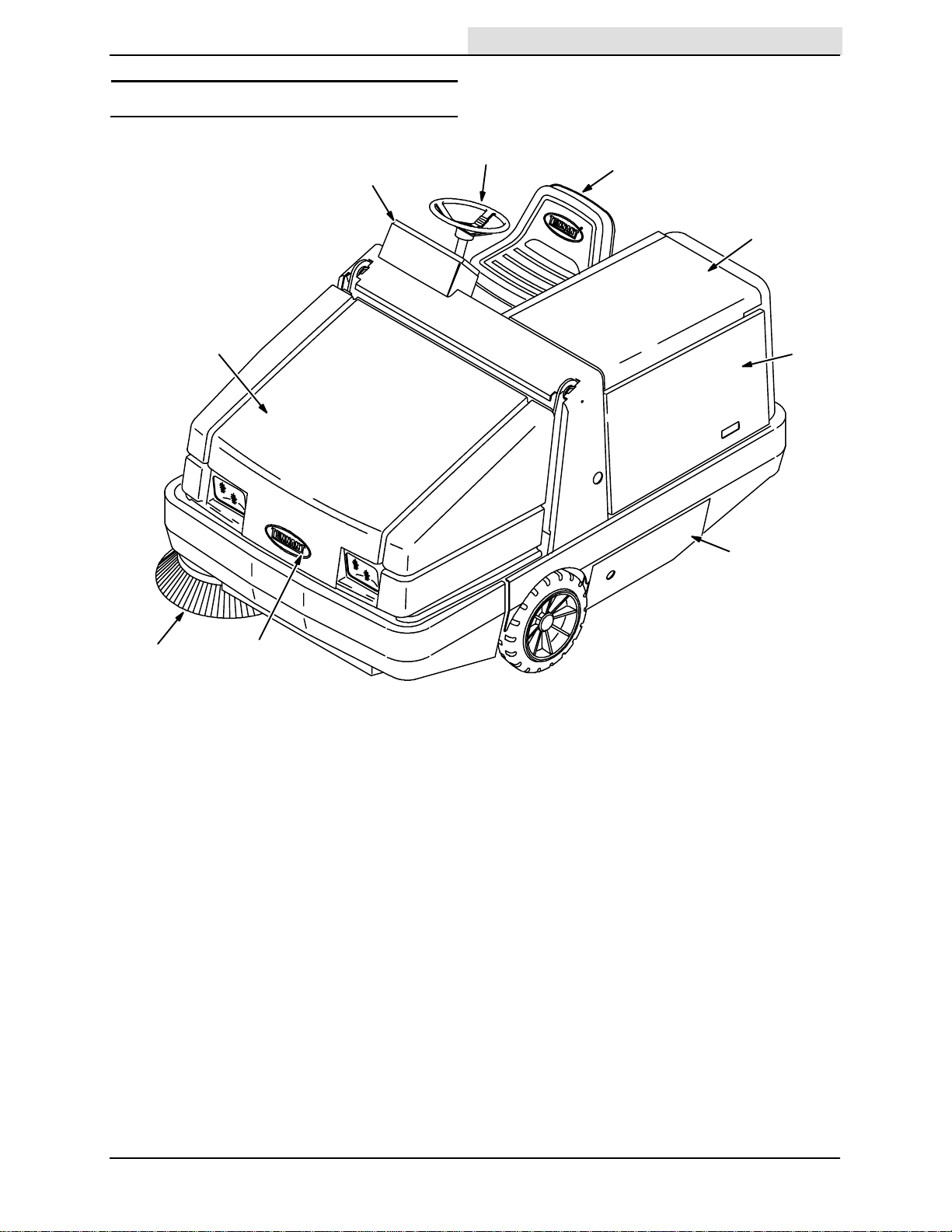
MACHINE COMPONENTS
Home
Find...
Go To..
OPERATION
B
I
F
A
C
D
E
H
G
07748
A. Operator Seat
B. Steering Wheel
C. Engine Cover
D. Engine Side Door
E. Main B rush Access Door
F. Hopper Cover
G. Hopper Access Cover
H. Side Brush
I. Instrument Panel
6500D 330290 (5-- 98)
9

OPERATION
Home
Find...
Go To..
CONTROL PANEL SYMBOLS
These symbols identify controls and displays on
the machine:
Main and Side Brushes On Charging System
Main Brush On Engine Oil Pressure
Hopper Door Open Engine Water Temperature
Hopper Door Close Hopper Temperature -- Thermo Sentryt
Hopper Down Hopper Temperature --Thermo Sentryt
Hopper Up Filter Clogged
Horn Hopper Door Closed
Main Brush Down Pressure Light Fuel
Main Brush Down Pressure Heavy Hourmeter
Main Brush Float Hazard Light
Main Brush Down Filter Shaker
Main Brush Up Operating Lights
10
Side Brush Down Pressure Light Fan
Side Brush Down Pressure Heavy Engine Speed
6500D 330290 (9-- 01)
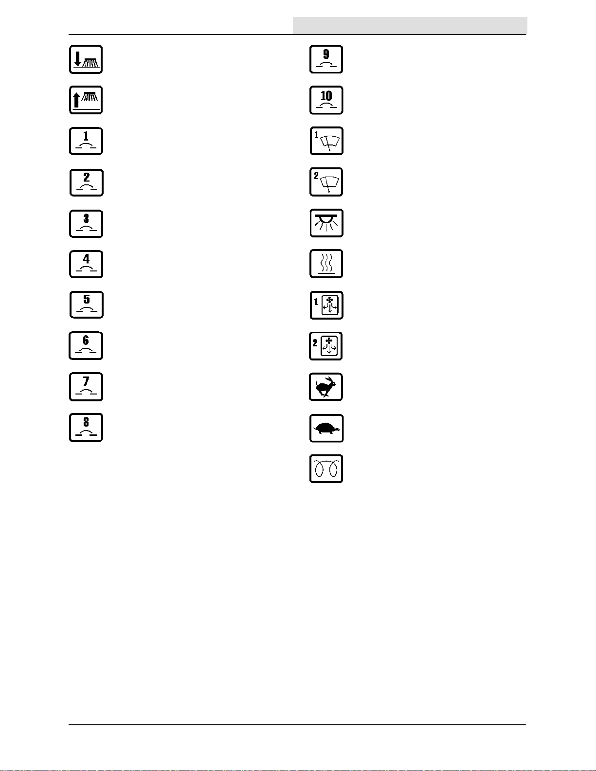
Side Brush Down Circuit Breaker 9
Home
Find...
Go To..
Side Brush Up Circuit Breaker 10
Circuit Breaker 1 Windshield Wiper Slow
Circuit Breaker 2 Windshield Wiper Fast
Circuit Breaker 3 Dome Light
Circuit Breaker 4 Heater
OPERATION
Circuit Breaker 5 Cab Pressurizer Slow
Circuit Breaker 6 Cab Pressurizer Fast
Circuit Breaker 7 Engine speed (fast)
Circuit Breaker 8 Engine speed (slow)
Diesel Preheat
6500D 330290 (9-- 01)
11
OPERATION
Y
Home
Find...
Go To..
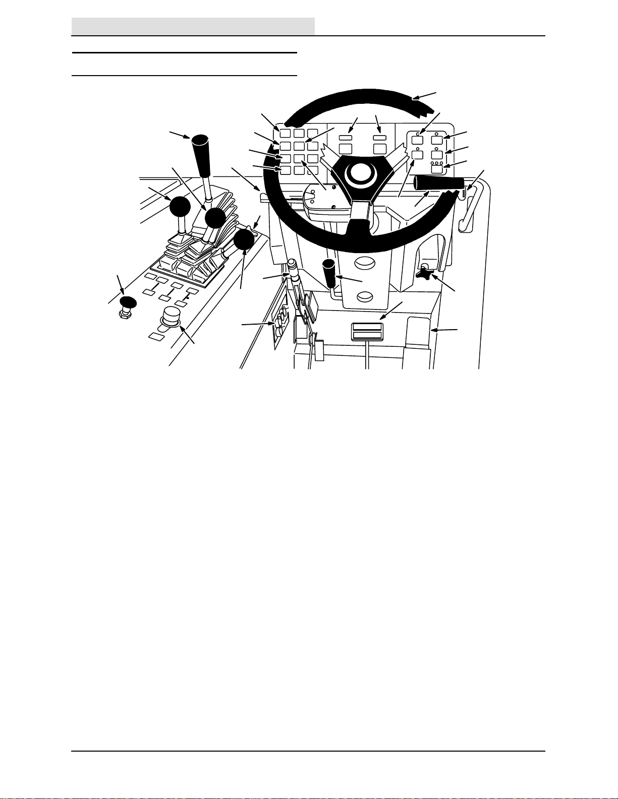
CONTROLS AND INSTRUMENTS
For machines below serial number 020000
O
I
G
F
N
M
L
K
J
S
R
Q
P
X
Z
T
U
V
W
AA
E
D
A. Directional Pedal
B. Brake Pedal
C. Parking Brake Lever
D. Horn Button
E. Engine Choke Knob
F. Main Brush And Side Brush Lever
G. Hopper Door Lever
H. Hopper Lift Lever
I. Main Brush Position Lever
J. Main Brush Down Pressure Knob
K. Turn Signal Switch (Option)
L. Hopper Temperature Light -- Thermo Sentryt
M. Engine Water Temperature Light
N. Engine Oil Pressure Light
O. Charging System Light
P. Hopper Door Light
Q. Clogged Filter Light
R. Fuel Level Gauge
S. Hourmeter
T. Hazard Light Switch (Option)
U. Operating Light Switch
V. Vacuum Fan Switch
W. Engine Speed Switch
X. Filter Shaker Switch
Y. Steering Wheel
Z. Side Brush Position Lever
AA. Ignition Switch
BB.Side Brush Down Pressure Knob
CC.Steering Column Tilt Lever
DD.Circuit Breakers
DD
C
H
CC
B
BB
A
08047
12
6500D 330290 (3-- 99)
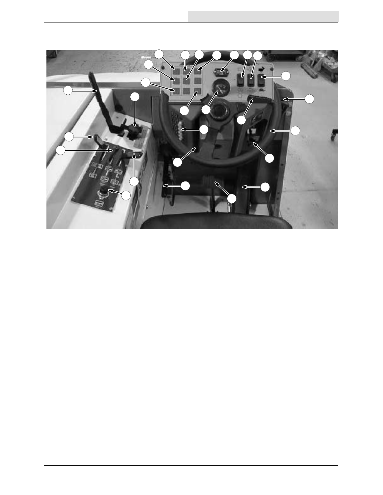
For machines with serial number 020000 and above
Home
Find...
Go To..
OPERATION
K
O
P
H
I
E
F
BB
G
D
M
L
Q
C
N
S
AA
T
R
B
U
V
Y
X
W
Z
A
A. Directional Pedal
B. Brake Pedal
C. Parking Brake Lever
D. Horn Button
E. Main Brush And Side Brush Lever
F. Hopper Door Lever
G. Hopper Lift Lever
H. Main Brush Position Lever
I. Main Brush Down Pressure Knob
J. Turn Signal Switch (Not Pictured)
K. Hopper Temperature Light -- Thermo Sentryt
L. Engine Water T emperature Light
M. Engine Oil Pressure Light
N. Charging System Light
O. Hopper Door Light
P. Clogged Filter Light (Option)
Q. Glow Plug light
R. Hourmeter
S. Fuel Gauge
T. Operating/Hazard Lights Switch
U. Vacuum Fan/Filter Shaker Switch
V. Engine Speed Switch
W. Steering Wheel
X. Side Brush Position Lever
Y. I g n i t i o n S w i t c h
Z. Side Brush Down Pressure Knob
AA. Circuit Breakers
BB.Steering Column Tilt Lever (Option)
6500D 330290 (9-- 02)
13
OPERATION
Home
Find...
Go To..
OPERATION OF CONTROLS
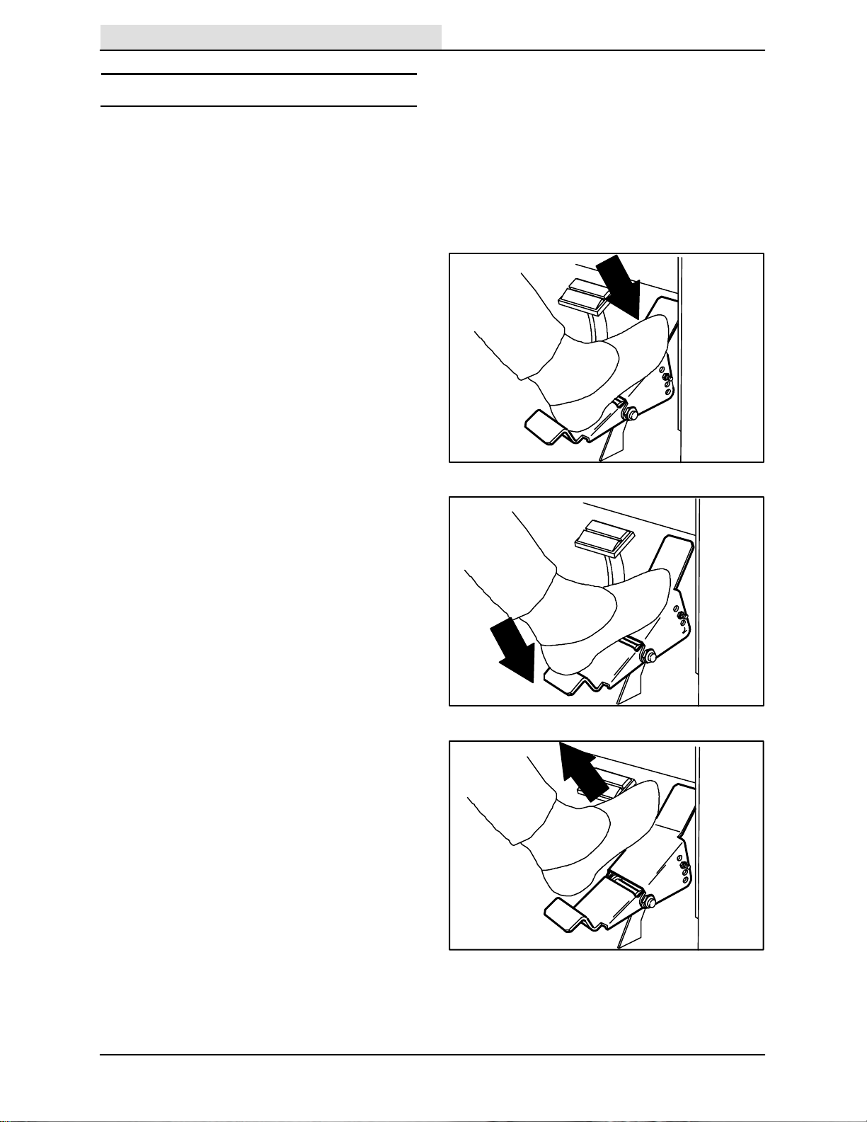
DIRECTIONAL PEDAL
The directional pedal controls direction of travel
and the propelling speed of the machine. You
change the speed of the machine with the
pressure of your foot; the harder you press the
faster the machine travels.
Forward: Press the top of the directional pedal
with the toe of your foot.
Reverse: Press the bottom of the directional
pedal with the heel of your foot.
Neutral: Take your foot off the directional pedal
and it will return to the neutral position.
07790
07791
14
07792
6500D 330290 (5-- 98)
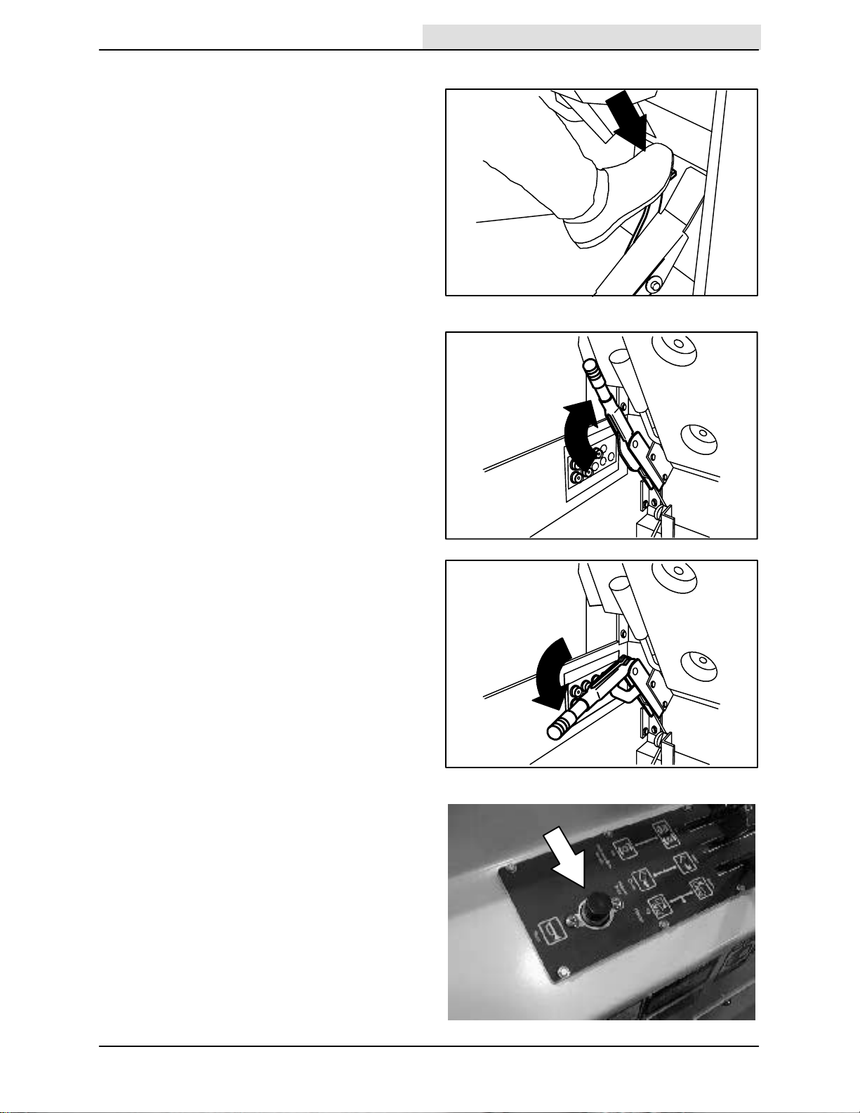
BRAKE PEDAL
Home
Find...
Go To..
The brake pedal stops the machine.
Stop: Take your foot off the directional pedal and
let it return to the neutral position. Step on the
brake pedal.
PARKING BRAKE LEVER
The parking brake lever sets and releases the
front wheel brakes.
Set: Pull the parking brake lever up.
FOR SAFETY: Before leaving or
servicing machine; stop on level
surface, set parking brake, turn off
machine and remove key.
OPERATION
07754
Release: Push the parking brake lever down.
HORN BUTTON
The horn button operates the horn.
Sound: Press the button.
07794
07793
6500D 330290 (9-- 01)
15
OPERATION
Home
Find...
Go To..
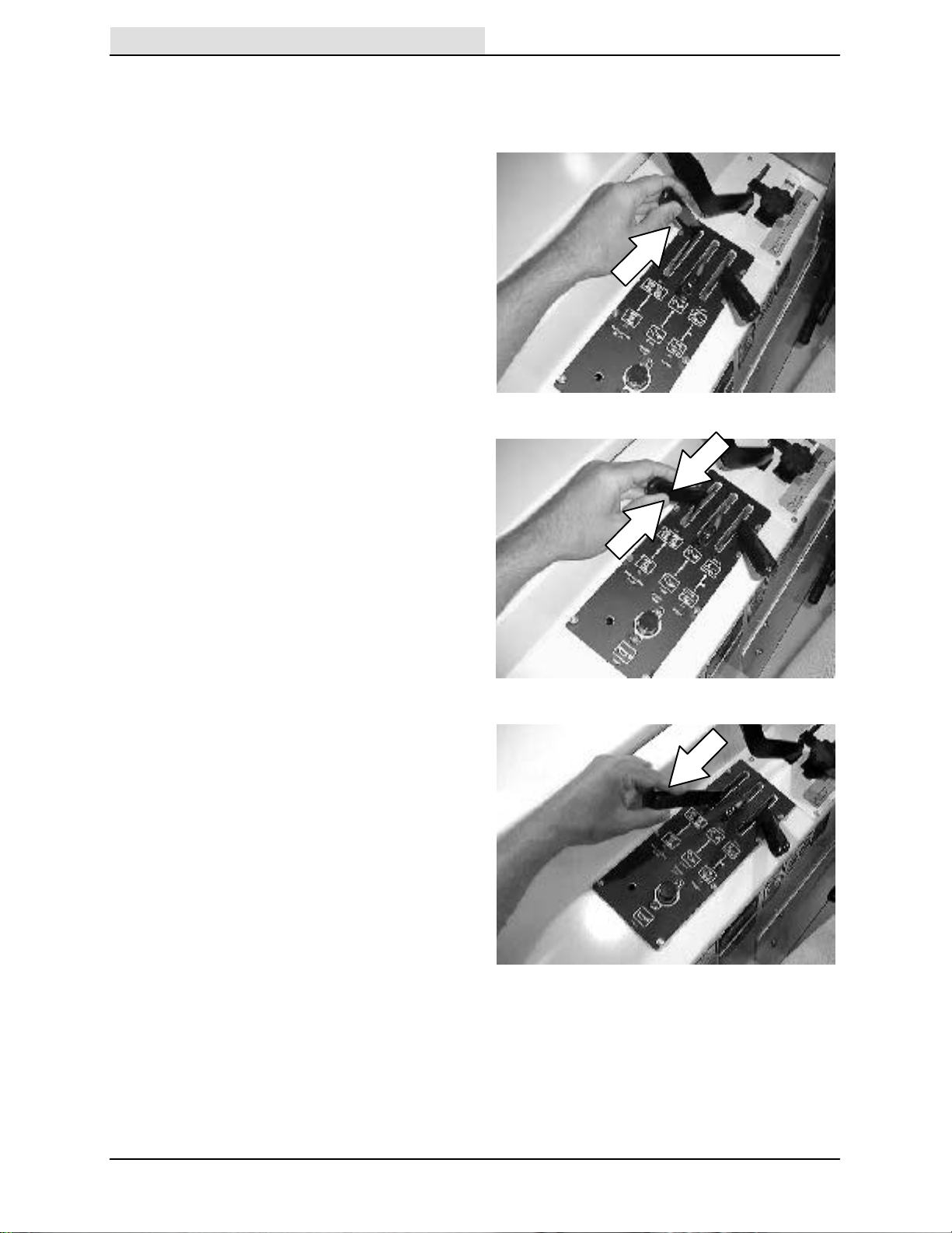
MAIN BRUSH AND SIDE BRUSH LEVER
The main brush and side brush lever controls the
main brush and side brush rotation.
Main Brush and Side Brush On: Push the main
brush and side brush lever into the On position.
Main Brush and Side Brush Off: Pull the main
brush and side brush lever into the middle
position.
Main Brush On: Pull the main brush and side
brush lever into the On position.
NOTE: Always raise the main brush when the
machine is not being operated for some time. This
prevents the main brush from getting a flat spot.
16
6500D 330290 (9-- 01)
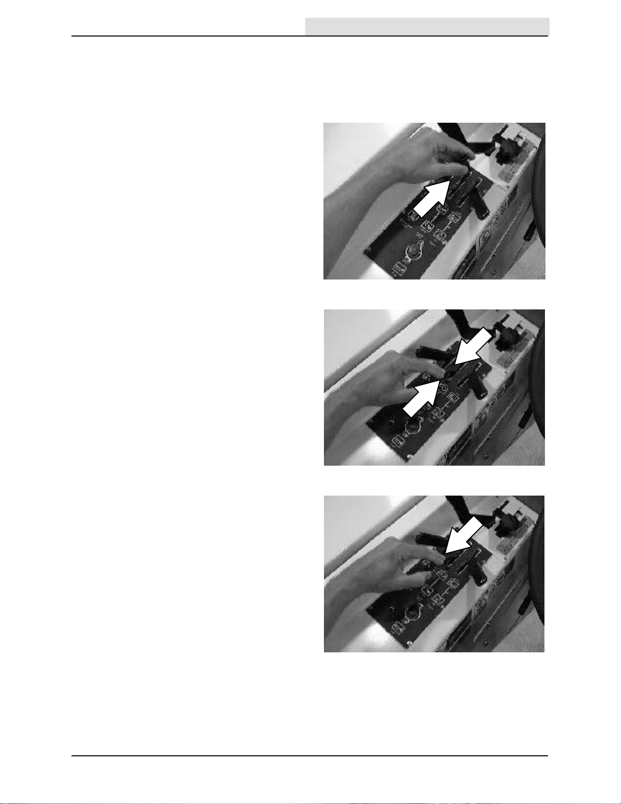
HOPPER DOOR LEVER
Home
Find...
Go To..
The hopper door lever opens and closes the
hopper door and dust door. Open the hopper door
when sweeping. Close the hopper door when
emptying the hopper to control debris and dust.
Open: Push the hopper door lever into the Open
position and leave it there.
Hold: Release the hopper door lever into the
middle position.
OPERATION
Close: Pull and hold the hopper door lever into
the Close position.
NOTE: The hopper door will not close if the main
brush, side brush, and vacuum fan are operating.
6500D 330290 (9-- 01)
17
OPERATION
Home
Find...
Go To..
HOPPER LIFT LEVER
The hopper lift lever raises and lowers the hopper.
Up: Pull and hold the hopper lift lever into the Up
position.
WARNING: Raised hopper may fall.
Engage hopper support bar.
NOTE: The hopper will not raise if the main brush,
side brush, and vacuum fan are operating.
Hold: Release the hopper lift lever up and into the
middle position.
Down: Push and hold the hopper lift lever into the
Down position.
18
6500D 330290 (9-- 01)
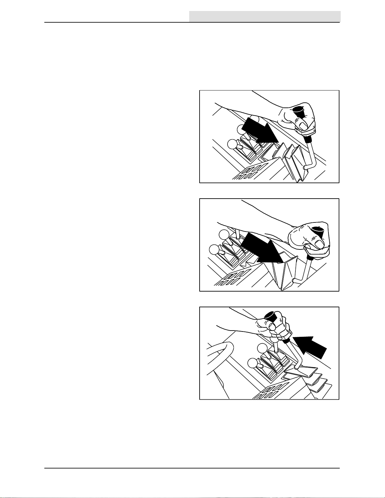
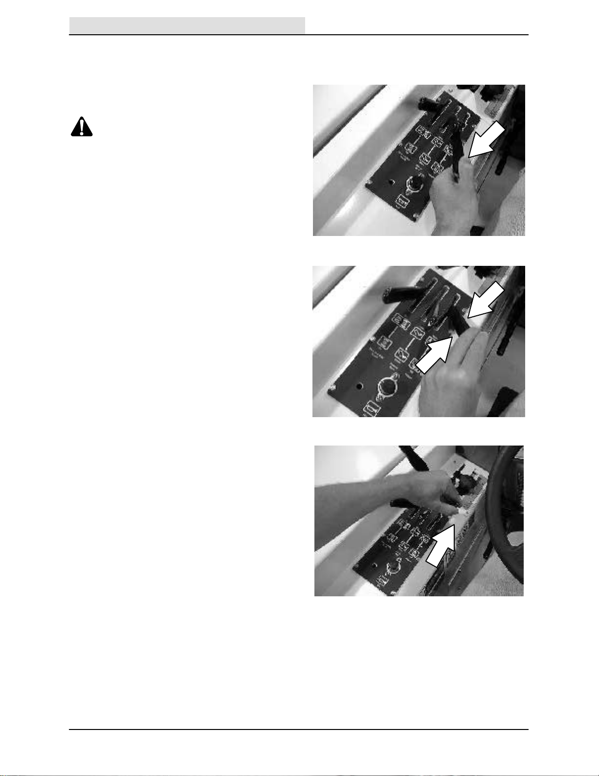
MAIN BRUSH POSITION LEVER
Home
Find...
Go To..
(For machines below serial number 020000)
The main brush position lever lowers and raises
the main brush. The main brush can be lowered
into two sweeping positions; down and float.
Down is used for general sweeping. Float is used
when sweeping extremely uneven surfaces.
Down: Pull the main brush position lever back
and to the left and over into the Down position.
Float: Pull the main brush position lever back and
to the left and over into the Float position.
OPERATION
07782
Up: Pull the main brush position lever all the way
back and to the right into the up position.
6500D 330290 (9-- 01)
07783
07784
19
OPERATION
Home
Find...
Go To..
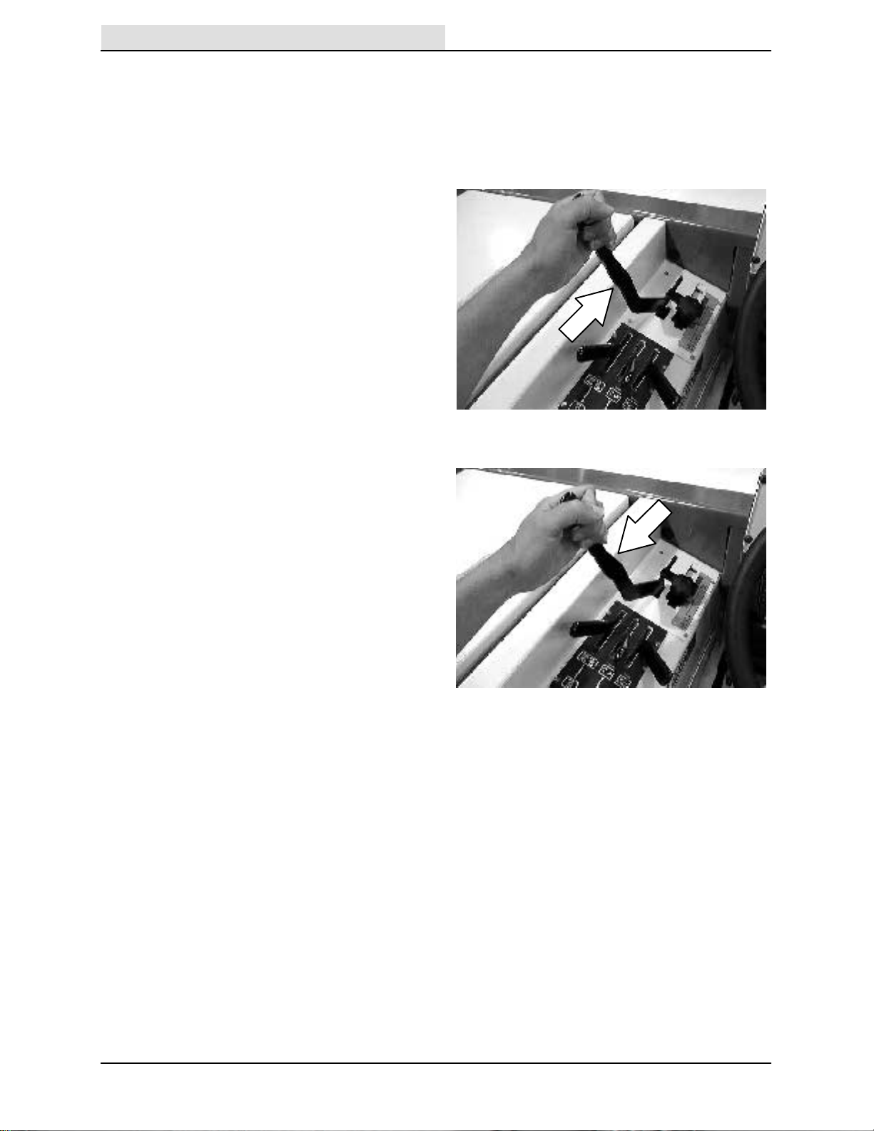
MAIN BRUSH POSITION LEVER (For
machines serial number 020000 and above)
The main brush position lever lowers and raises
the main brush. The main brush can be lowered
into one sweeping position, which is set by the
main brush adjustment knob.
Down: Pull the main brush position lever back
and to the left and over into the down position.
Up: Pull the main brush position lever all the way
back and to the right into the Up position.
20
6500D 330290 (9-- 01)
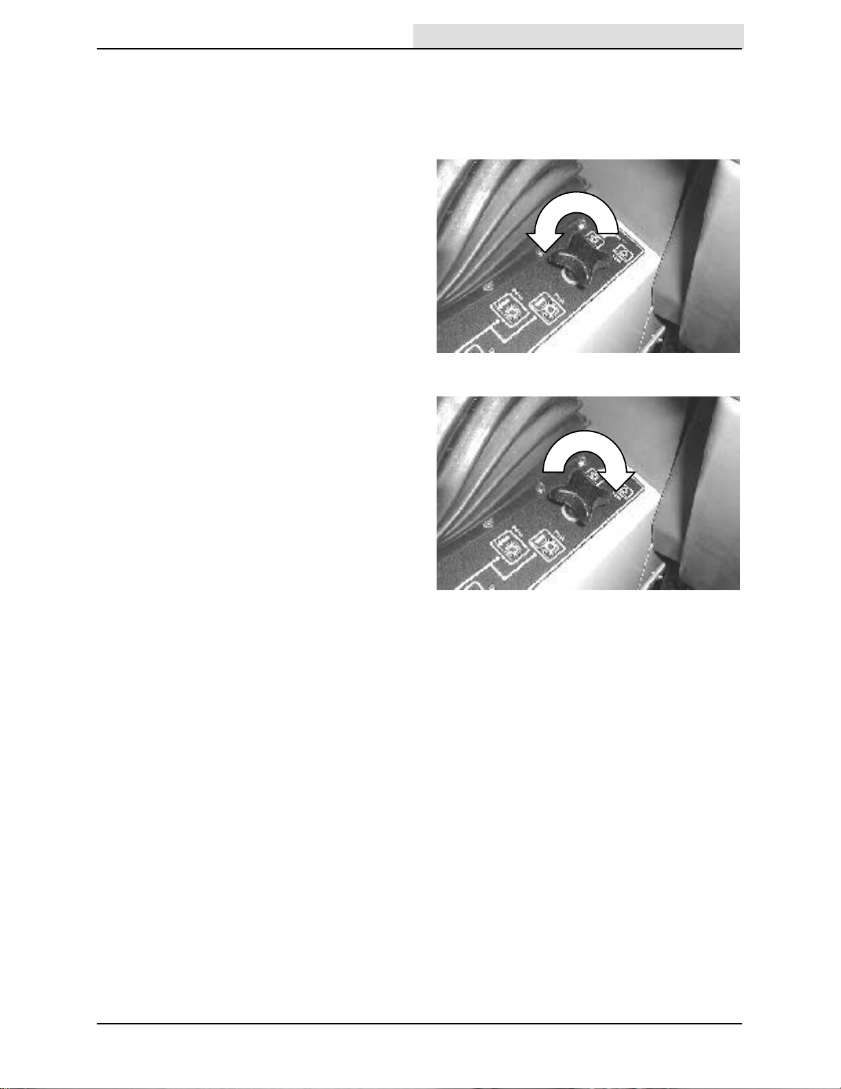
MAIN BRUSH DOWN PRESSURE KNOB
Home
Find...
Go To..
(For machines below serial number 020000)
The main brush down pressure knob changes the
main brush contact with the sweeping surface.
Heavy: Turn the main brush down pressure knob
counter-clockwise.
Light: Turn the main brush down pressure knob
clockwise.
OPERATION
6500D 330290 (9-- 01)
21
OPERATION
Home
Find...
Go To..
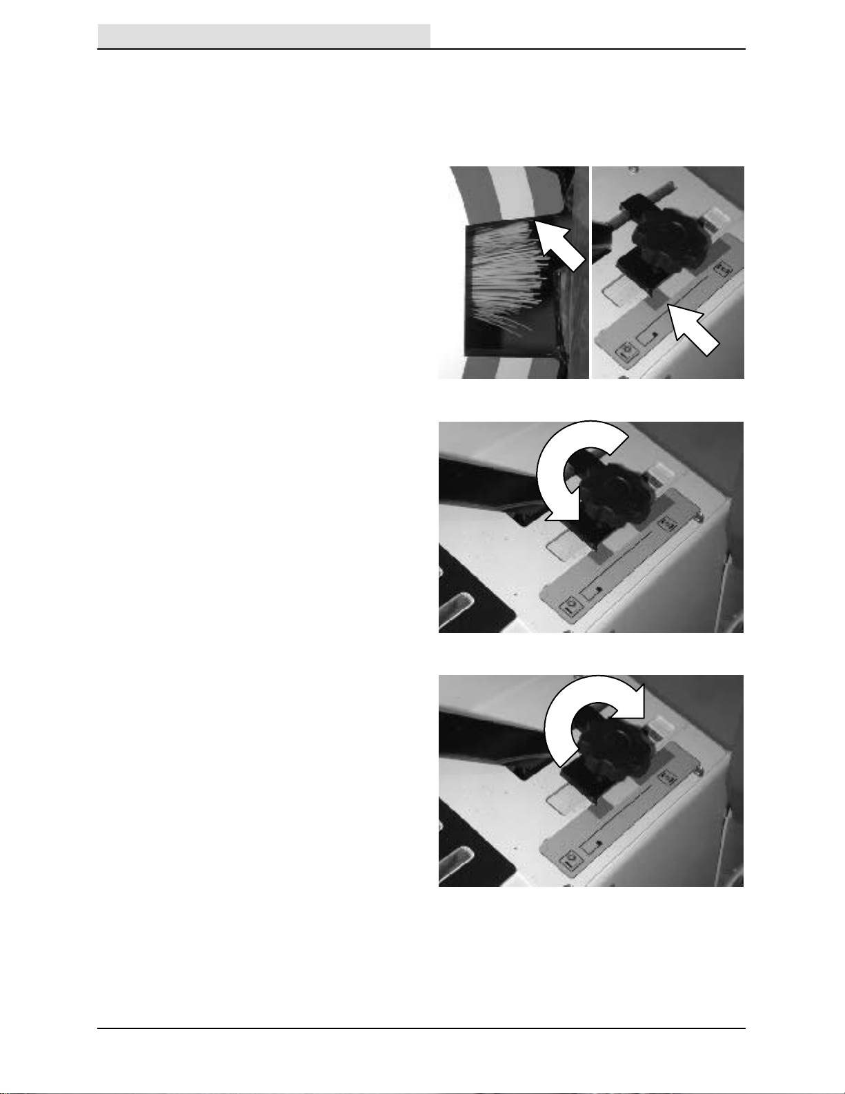
MAIN BRUSH ADJUSTMENT KNOB (For
machines serial number 020000 and above)
The main brush adjustment knob controls the
amount of contact the main brush has with the
sweeping surface.
Note the length of the main brush bristles with the
color band on the brush idler plate before moving
the main brush adjustment knob.
Align the pointer from the plate located under the
knob, to match the same color band as the brush
idler plate.
Loosen adjustment knob: Turn the adjustment
plate knob counter--clockwise until the plate can
slide along the adjustment panel.
Secure adjustment knob: Turn the adjustment
plate knob clockwise until the knob is hand tight
and the plate cannot slide in the adjustment panel.
22
6500D 330290 (9-- 01)
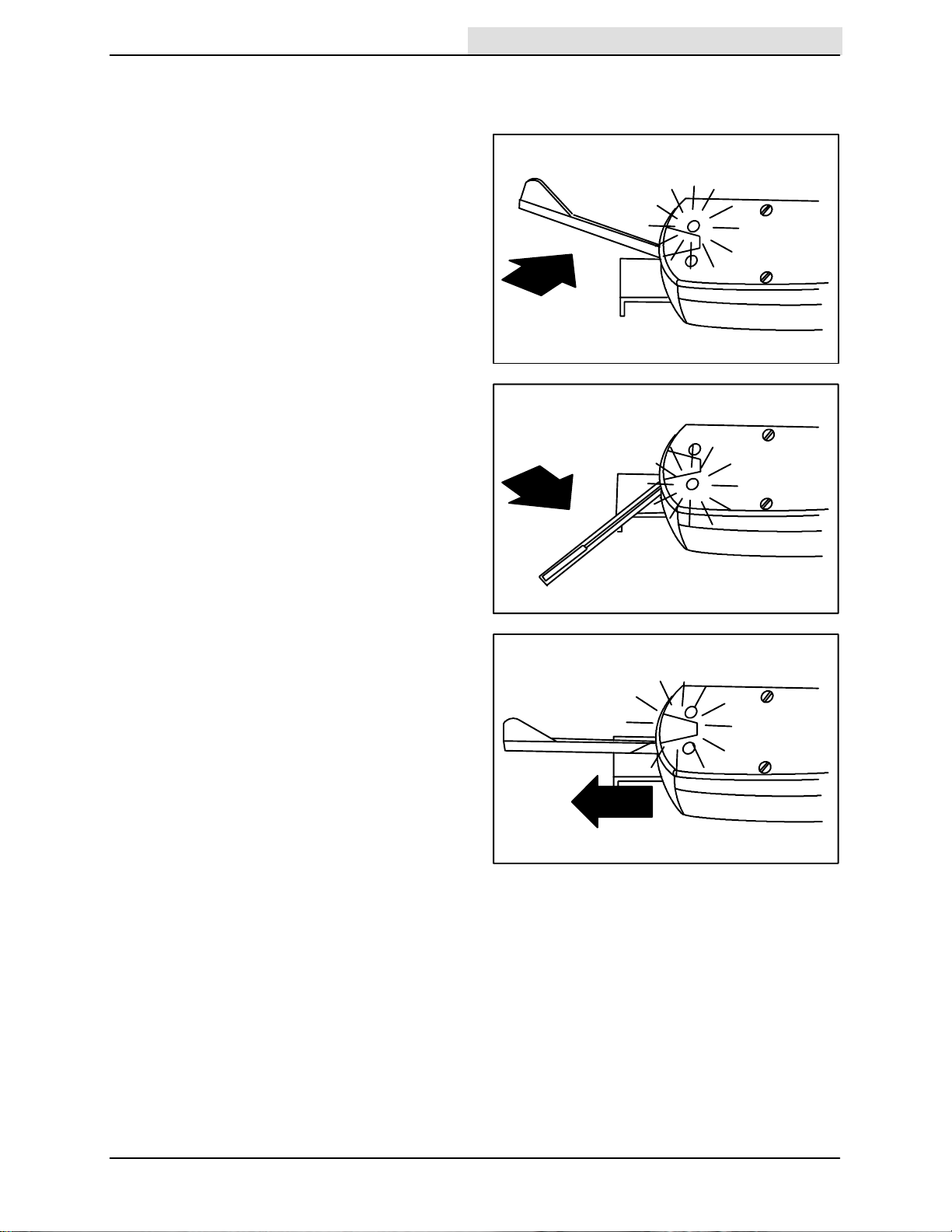
TURN SIGNAL SWITCH (OPTION)
Home
Find...
Go To..
The turn signal switch operates the turn signals.
Right: Push the switch lever forward.
Left: Pull the switch lever back.
OPERATION
06487
Flashers: Pull out the knob.
06488
06745
6500D 330290 (9-- 01)
23
OPERATION
0776
0
Home
Find...
Go To..
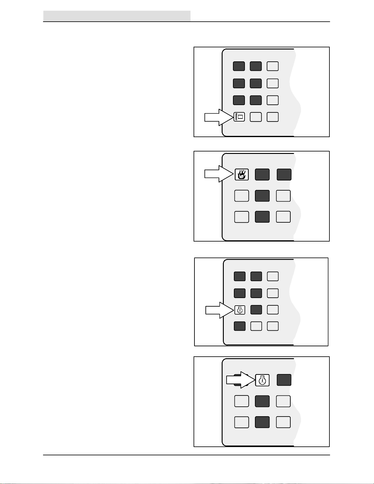
HOPPER TEMPERATURE LIGHT -- THERMO
SENTRYt
The hopper temperature light comes on when
there is too much heat in the hopper, possibly
from a fire. The Thermo Sentry will stop the
vacuum fan.
The Thermo Sentryt has to be reset manually,
see THERMO SENTRY in MAINTENANCE.
(For machines below serial number 020000)
The light location is as shown.
(For machines serial number 020000 and
above)
The light location is as shown.
ENGINE WATER TEMPERATURE LIGHT
The engine water temperature light comes on
when the temperature of the engine coolant is
more than 107_ C (225_ F). Stop operating the
machine. Locate the problem and have it
corrected.
(For machines below serial number 020000)
The light location is as shown.
(For machines serial number 020000 and
above)
The light location is as shown.
07759
24
6500D 330290 (9-- 01)
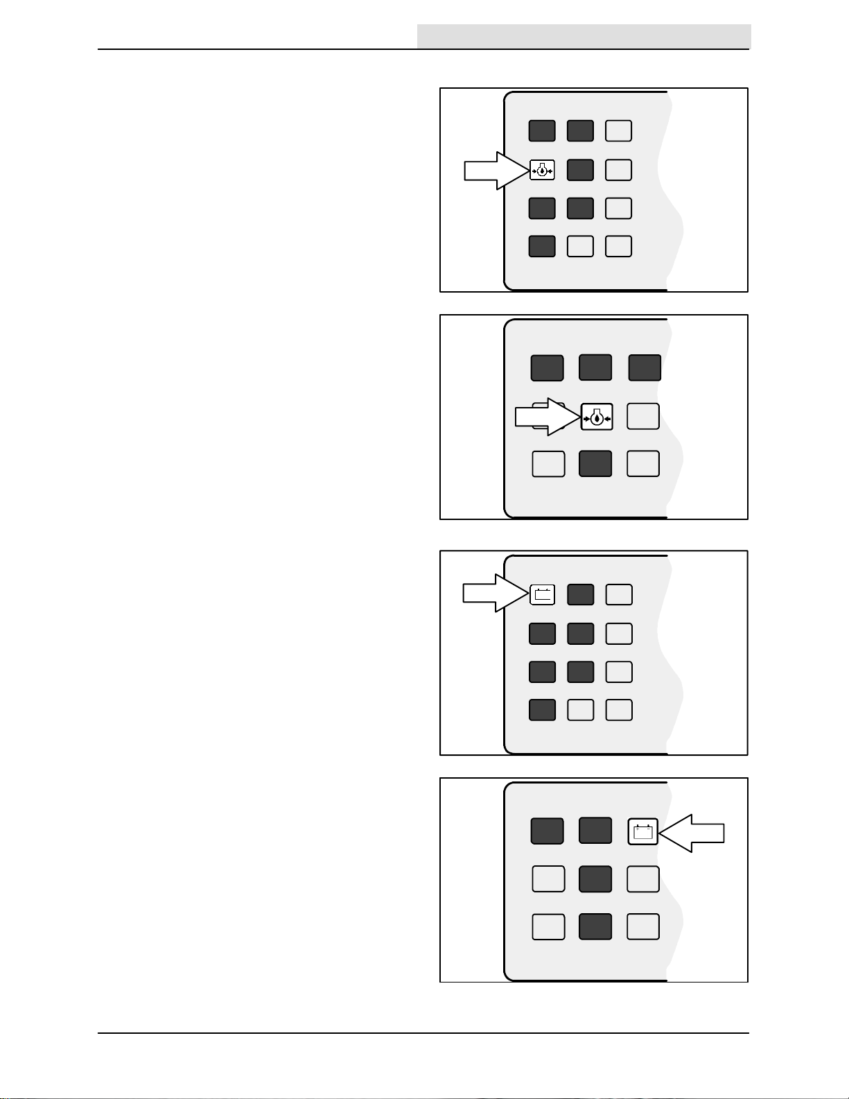
ENGINE OIL PRESSURE LIGHT
Home
Find...
Go To..
The engine oil pressure light comes on when the
engine oil pressure falls below 35 kPa (5 psi).
Stop operating the machine. Locate the problem
and have it corrected.
(For machines below serial number 020000)
The light location is as shown.
(For machines serial number 020000 and
above)
The light location is as shown.
OPERATION
07758
CHARGING SYSTEM LIGHT
The charging system light comes on when the
existing voltage potential of the battery is not
within normal range -- 10 to 14 Volts. Stop
operating the machine. Locate the problem and
have it corrected.
(For machines below serial number 020000)
The light location is as shown.
(For machines serial number 020000 and
above)
The light location is as shown.
07757
6500D 330290 (9-- 01)
25

OPERATION
Home
Find...
Go To..
HOPPER DOOR LIGHT
The hopper door light comes on when the hopper
door is closed. Make sure the hopper door is open
and the hopper door light is off, before sweeping
with the machine.
(For machines below serial number 020000)
The light location is as shown.
(For machines serial number 020000 and
above)
The light location is as shown.
07763
CLOGGED FILTER LIGHT
The clogged filter light comes on when the hopper
dust filter is clogged.
To clean the filter, press the filter shaker switch. If
the clogged filter light remains lit, manually clean
the hopper dust filter. See HOPPER DUST
FILTER in MAINTENANCE.
(For machines below serial number 020000)
The light location is as shown.
CLOGGED FILTER LIGHT (OPTION)
(For machines serial number 020000 and
above)
The light location is as shown.
07762
26
6500D 330290 (9-- 01)
GLOW PLUG LIGHT (For machines serial
Home
Find...
Go To..
number 020000 and above ONLY)
The glow plug light comes on when the ignition
switch is turned counterclockwise to the preheat
position. The light will go out when the engine is
ready to start.
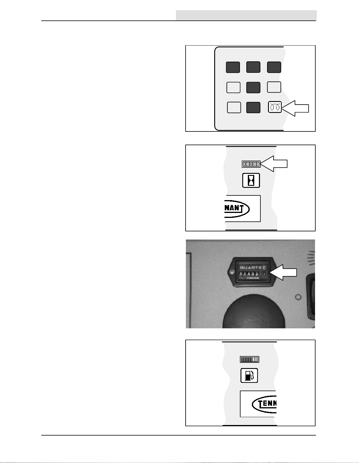
HOURMETER
The hourmeter records the number of hours the
machine has been operated. Use this information
to determine machine maintenance intervals.
(For machines below serial number 020000)
The light location is as shown.
OPERATION
(For machines serial number 020000 and
above)
The light location is as shown.
FUEL LEVEL GAUGE (For machines below
serial number 020000)
The fuel level gauge indicates how much fuel is in
the fuel tank with a segmented LED light. When
the tank is full, all ten of the segments are lit. As
the fuel tank empties, the segments shut off. The
fuel tank is empty when all ten of the segments
have shut off.
NOTE: Do not let the fuel tank empty completely.
Air can enter the fuel system. The fuel system will
need bleeding before the next engine start.
07765
6500D 330290 (9-- 01)
07764
27
OPERATION
Home
Find...
Go To..
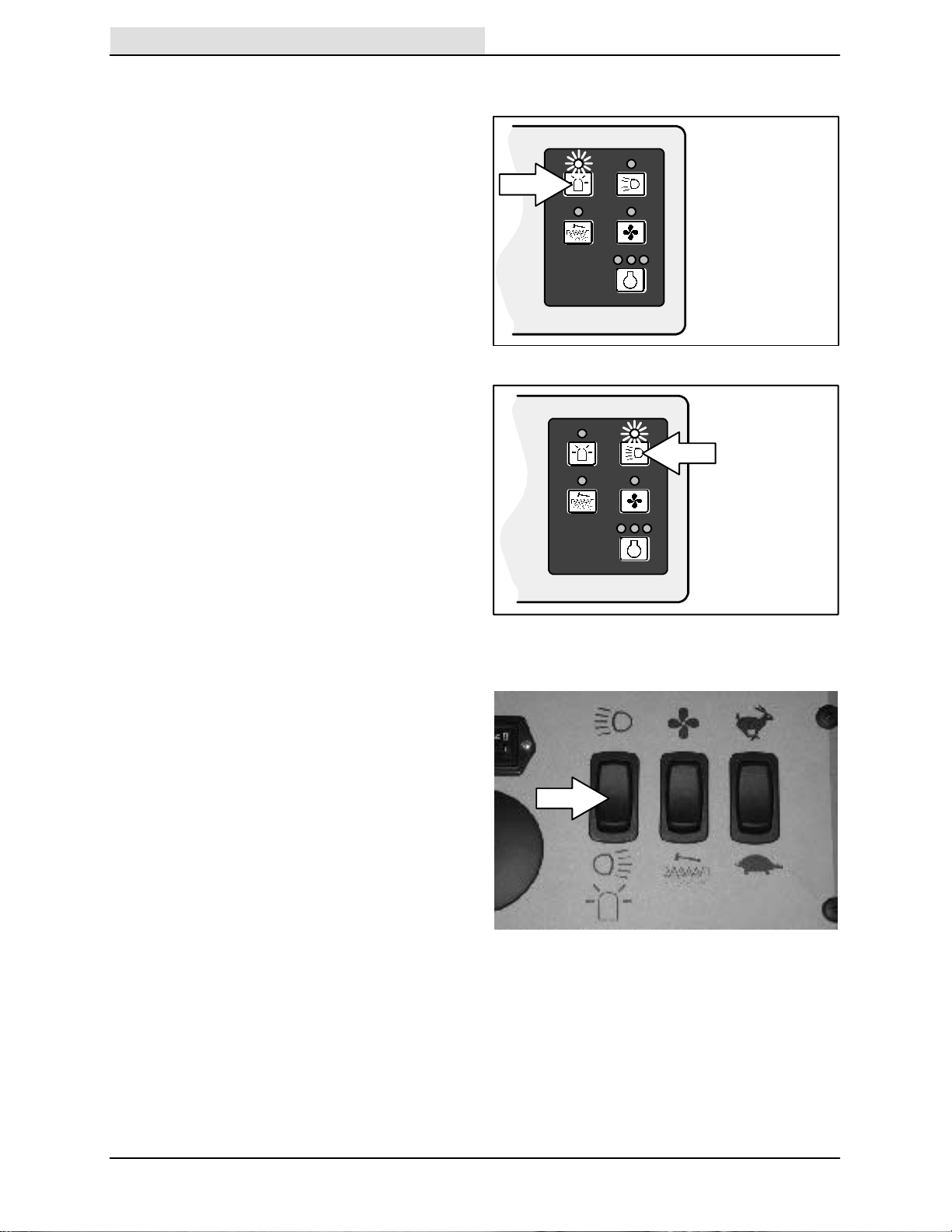
HAZARD LIGHT SWITCH (OPTION)
(For machines below serial number 020000)
The hazard light switch powers on and off the
hazard light.
On: Press the hazard light switch. The indicator
light above the switch will come on.
Off: Press the hazard light switch. The indicator
light above the switch will go off.
OPERATING LIGHTS SWITCH
(For machines below serial number 020000)
The operating lights switch powers on and off the
headlights and taillights.
On: Press the operating lights switch. The
indicator light above the switch will come on.
Off: Press the operating lights switch. The
indicator light above the switch will go off.
OPERATING/HAZARD LIGHTS SWITCH (For
machines serial number 020000 and above)
The operating/hazard light switch powers on and
off the operating/hazard lights.
Operating Lights On: Press the top of the switch.
Operating/Hazard Lights On: Press the bottom of
the switch.
07766
07768
Off: Press the switch to the middle off position.
28
6500D 330290 (9-- 01)
 Loading...