

Tennant 355E User Manual
355E
Home
Find...
Operator Manual
MM306

This manual is furnished with each new TENNANT Model 355E. It provides necessary operating and
Home
Find...
preventive maintenance instructions. Read this manual completely and understand the machine before
operating or servicing it.
This machine will provide excellent service. However, the best results will be obtained at minimum
costs if:
The machine is operated with reasonable care.
The machine is maintained regularly – per the maintenance instructions provided.
The machine is maintained with TENNANT supplied or approved parts.
Manual Number – MM306
Revision: 08
Published:3–97
Copyright 1992, 1993, 1994, 1995, 1996, 1997 TENNANT, Printed in U.S.A.

CONTENTS
Home
Find...
CONTENTS
SAFETY PRECAUTIONS 3. . . . . . . . . . . . . . . . .
OPERATION 5. . . . . . . . . . . . . . . . . . . . . . . . . . . .
OPERATOR RESPONSIBILITY 5. . . . . . . . .
MACHINE COMPONENTS 6. . . . . . . . . . . . .
CONTROL PANEL SYMBOLS 7. . . . . . . . . .
CONTROLS AND INSTRUMENTS 9. . . . . .
OPERATION OF CONTROLS 10. . . . . . . . . .
DIRECTIONAL PEDAL 10. . . . . . . . . . . . . .
DIRECTIONAL PEDAL TOE ANGLE
(OPTION) 11. . . . . . . . . . . . . . . . . . . . . .
BRAKE PEDAL 11. . . . . . . . . . . . . . . . . . . .
PARKING BRAKE LEVER 11. . . . . . . . . . .
HORN BUTTON 12. . . . . . . . . . . . . . . . . . . .
BRUSH PRESSURE GAUGE 12. . . . . . . .
MAIN BRUSH AND SIDE BRUSH
LEVER 13. . . . . . . . . . . . . . . . . . . . . . . . .
HOPPER DOOR LEVER 14. . . . . . . . . . . .
HOPPER LIFT LEVER 15. . . . . . . . . . . . . .
MAIN BRUSH POSITION LEVER 16. . . .
MAIN BRUSH DOWN PRESSURE
KNOB 17. . . . . . . . . . . . . . . . . . . . . . . . . .
POWER KILL SWITCH 17. . . . . . . . . . . . . .
HOPPER TEMPERATURE LIGHT –
THERMO SENTRY 18. . . . . . . . . . . .
HOPPER DOOR LIGHT 18. . . . . . . . . . . . .
CLOGGED FILTER LIGHT 18. . . . . . . . . .
MAIN BRUSH SHUT DOWN LIGHT 18. .
BATTERY DISCHARGE INDICATOR 19.
HOURMETER 19. . . . . . . . . . . . . . . . . . . . .
HAZARD LIGHT SWITCH (OPTION) 19. .
OPERATING LIGHTS SWITCH 19. . . . . .
VACUUM FAN SWITCH 20. . . . . . . . . . . . .
FILTER SHAKER SWITCH 20. . . . . . . . . .
STEERING WHEEL 20. . . . . . . . . . . . . . . .
SIDE BRUSH POSITION LEVER 21. . . . .
ON-OFF SWITCH 22. . . . . . . . . . . . . . . . . .
SIDE BRUSH DOWN PRESSURE
KNOB 23. . . . . . . . . . . . . . . . . . . . . . . . . .
STEERING COLUMN TILT LEVER 23. . .
CIRCUIT BREAKERS 24. . . . . . . . . . . . . . .
LATCHES 24. . . . . . . . . . . . . . . . . . . . . . . . .
OPERATOR SEAT 25. . . . . . . . . . . . . . . . . .
HOPPER SUPPORT BAR 26. . . . . . . . . . .
HOW THE MACHINE WORKS 27. . . . . . . . . .
PRE-OPERATION CHECKLIST 27. . . . . . . . .
STARTING THE MACHINE 28. . . . . . . . . . . . .
SWEEPING AND BRUSH INFORMATION 29
SWEEPING 30. . . . . . . . . . . . . . . . . . . . . . . . . .
STOP SWEEPING 32. . . . . . . . . . . . . . . . . . . .
EMPTYING THE HOPPER 33. . . . . . . . . . . . .
STOP THE MACHINE 35. . . . . . . . . . . . . . . . .
POST-OPERATION CHECKLIST 36. . . . . . . .
Page
Page
ENGAGING HOPPER SUPPORT BAR 37. .
DISENGAGING HOPPER SUPPORT BAR 38
OPERATION ON INCLINES 39. . . . . . . . . . . .
OPTIONS 40. . . . . . . . . . . . . . . . . . . . . . . . . . . .
TIE-DOWNS 40. . . . . . . . . . . . . . . . . . . . . . .
MACHINE TROUBLESHOOTING 41. . . . . . .
MAINTENANCE 42. . . . . . . . . . . . . . . . . . . . . . . . .
MAINTENANCE CHART 42. . . . . . . . . . . . . . .
LUBRICATION 44. . . . . . . . . . . . . . . . . . . . . . . .
PROPELLING GEARBOX 44. . . . . . . . . . .
REAR WHEEL SUPPORT BEARING 44.
STEERING LINK 44. . . . . . . . . . . . . . . . . . .
FRONT WHEEL BEARINGS 45. . . . . . . . .
HYDRAULICS 45. . . . . . . . . . . . . . . . . . . . . . . .
HYDRAULIC FLUID RESERVOIR 45. . . .
HYDRAULIC FLUID 46. . . . . . . . . . . . . . . .
HYDRAULIC HOSES 47. . . . . . . . . . . . . . .
BATTERIES 47. . . . . . . . . . . . . . . . . . . . . . . . . .
CHARGING THE BATTERIES 48. . . . . . .
BELTS AND CHAINS 50. . . . . . . . . . . . . . . . . .
VACUUM FAN DRIVE BELT 50. . . . . . . . .
STATIC DRAG CHAIN 50. . . . . . . . . . . . . .
DEBRIS HOPPER 51. . . . . . . . . . . . . . . . . . . . .
HOPPER DUST FILTER 51. . . . . . . . . . . . .
TO REPLACE HOPPER DUST
FILTER 52. . . . . . . . . . . . . . . . . . . . . .
THERMO SENTRY 53. . . . . . . . . . . . . . .
BRUSHES 54. . . . . . . . . . . . . . . . . . . . . . . . . . . .
MAIN BRUSH 54. . . . . . . . . . . . . . . . . . . . . .
TO REPLACE MAIN BRUSH 54. . . . . .
TO CHECK AND ADJUST MAIN
BRUSH PATTERN 55. . . . . . . . . . . .
SIDE BRUSH 57. . . . . . . . . . . . . . . . . . . . . .
TO REPLACE SIDE BRUSH 58. . . . . .
SIDE BRUSH GUARD 58. . . . . . . . . . . . . .
SKIRTS AND SEALS 59. . . . . . . . . . . . . . . . . .
HOPPER LIP SKIRTS 59. . . . . . . . . . . . . . .
HOPPER SIDE SKIRT 59. . . . . . . . . . . . . .
BRUSH DOOR SKIRTS 59. . . . . . . . . . . . .
REAR SKIRTS 60. . . . . . . . . . . . . . . . . . . . .
BRUSH DOOR SEALS 60. . . . . . . . . . . . . .
HOPPER SEALS 60. . . . . . . . . . . . . . . . . . .
HOPPER INSPECTION DOOR SEAL 60.
HOPPER DOOR SEALS 61. . . . . . . . . . . .
HOPPER COVER SEAL 61. . . . . . . . . . . . .
HOPPER DUST SEAL 61. . . . . . . . . . . . . .
HOPPER VACUUM FAN SEAL 61. . . . . . .
BRAKES AND TIRES 62. . . . . . . . . . . . . . . . . .
SERVICE BRAKES 62. . . . . . . . . . . . . . . . .
PARKING BRAKE 62. . . . . . . . . . . . . . . . . .
TIRES 62. . . . . . . . . . . . . . . . . . . . . . . . . . . .
REAR WHEEL 62. . . . . . . . . . . . . . . . . . . . .
355E MM306 (3–96)
1

CONTENTS
Home
Find...
PUSHING OR TOWING MACHINE 62. . . . . .
MACHINE JACKING 63. . . . . . . . . . . . . . . . . . .
ELECTRIC MOTORS 63. . . . . . . . . . . . . . . . . .
STORING MACHINE 63. . . . . . . . . . . . . . . . . .
SPECIFICATIONS 64. . . . . . . . . . . . . . . . . . . . . . .
GENERAL MACHINE PERFORMANCE 64. .
POWER TYPE 65. . . . . . . . . . . . . . . . . . . . . . . .
STEERING 65. . . . . . . . . . . . . . . . . . . . . . . . . . .
HYDRAULIC SYSTEM 65. . . . . . . . . . . . . . . . .
BRAKING SYSTEM 65. . . . . . . . . . . . . . . . . . .
TIRES 65. . . . . . . . . . . . . . . . . . . . . . . . . . . . . . .
INDEX 66. . . . . . . . . . . . . . . . . . . . . . . . . . . . . . . . . .
Page
2
355E MM306 (5–95)

SAFETY PRECAUTIONS
Home
Find...
SAFETY PRECAUTIONS
The following precautions are used throughout
this manual as indicated in their description:
WARNING: To warn of hazards or
unsafe practices which could result in
severe personal injury or death.
FOR SAFETY: To identify actions which
must be followed for safe operation of
equipment.
The machine is suited to sweep disposable
debris. Do not use the machine other than
described in this Operator Manual. The machine
is not designed for use on public roads.
The following information signals potentially
dangerous conditions to the operator or
equipment:
FOR SAFETY:
1. Do not operate machine:
– Unless trained and authorized.
– Unless operator manual is read and
understood.
– If it is not in proper operating
condition.
– In flammable or explosive areas unless
designed for use in those areas.
– In areas with possible falling objects
unless equipped with overhead guard.
2. Before starting machine:
– Check for fuel, oil, and liquid leaks.
– Keep sparks and open flame away
from refueling area.
– Make sure all safety devices are in
place and operate properly.
– Check brakes and steering for proper
operation.
3. When starting machine:
– Keep foot on brake and directional
pedal in neutral.
– Do not carry passengers on machine.
– Always follow safety and traffic rules.
– Report machine damage or faulty
operation immediately.
5. Before leaving or servicing machine:
– Stop on level surface.
– Set parking brake.
– Turn off machine and remove key.
6. When servicing machine:
– Avoid moving parts. Do not wear loose
jackets, shirts, or sleeves.
– Block machine tires before jacking
machine up.
– Jack machine up at designated
locations only. Block machine up with
jack stands.
– Use hoist or jack of adequate capacity
to lift machine.
– Wear eye and ear protection when
using pressurized air or water.
– Disconnect battery connections before
working on machine.
– Avoid contact with battery acid.
– Use cardboard to locate leaking
hydraulic fluid under pressure.
– Use TENNANT supplied or approved
replacement parts.
WARNING: Batteries emit hydrogen gas.
Explosion or fire can result. Keep
sparks and open flame away. Keep
covers open when charging.
WARNING: Hazardous voltage. Shock
can result. Disconnect batteries before
working on machine. Only qualified
personnel should work inside panel.
WARNING: Raised hopper may fall.
Engage hopper support bar.
WARNING: Lift arm pinch point. Stay
clear of hopper lift arms.
4. When using machine:
– Use brakes to stop machine.
– Go slow on inclines and slippery
surfaces.
– Use care when reversing machine.
– Move machine with care when hopper
is raised.
– Make sure adequate clearance is
available before raising hopper.
355E MM306 (12–92)
3
SAFETY PRECAUTIONS
Home
Find...
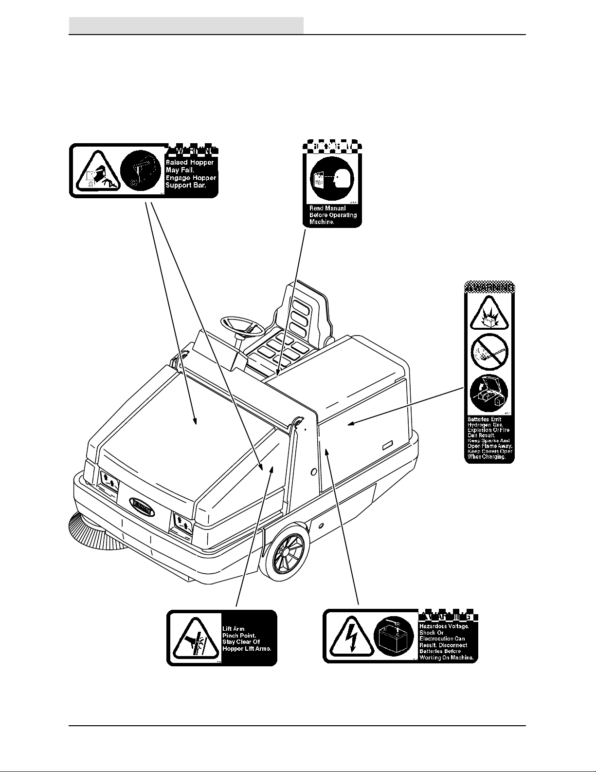
The following safety labels are mounted on the
machine in the locations indicated. If these or any
label becomes damaged or illegible, install a new
label in its place.
HOPPER SUPPORT BAR LABEL – LOCATED
ON THE HOPPER SUPPORT BAR AND ON
BOTH HOPPER LIFT ARMS.
FOR SAFETY LABEL – LOCATED ON THE
SIDE PANEL OF THE OPERATOR
COMPARTMENT.
BATTERY CHARGING LABEL – LOCATED ON
THE RELAY PANEL NEXT TO THE
BATTERIES.
HOPPER LIFT ARMS LABEL – LOCATED ON
BOTH HOPPER LIFT ARMS.
4
07985
HARARDOUS VOLTAGE LABEL – LOCATED
ON THE ELECTRICAL COMPONENTS BOX
COVER.
355E MM306 (6–93)
OPERATOR RESPONSIBILITY
Home
Find...
The operator’s responsibility is to take care
of the daily maintenance and checkups of
the machine to keep it in good working
condition. The operator must inform the
service mechanic or supervisor when the
required maintenance intervals occur as
stated in the MAINTENANCE section of this
manual.
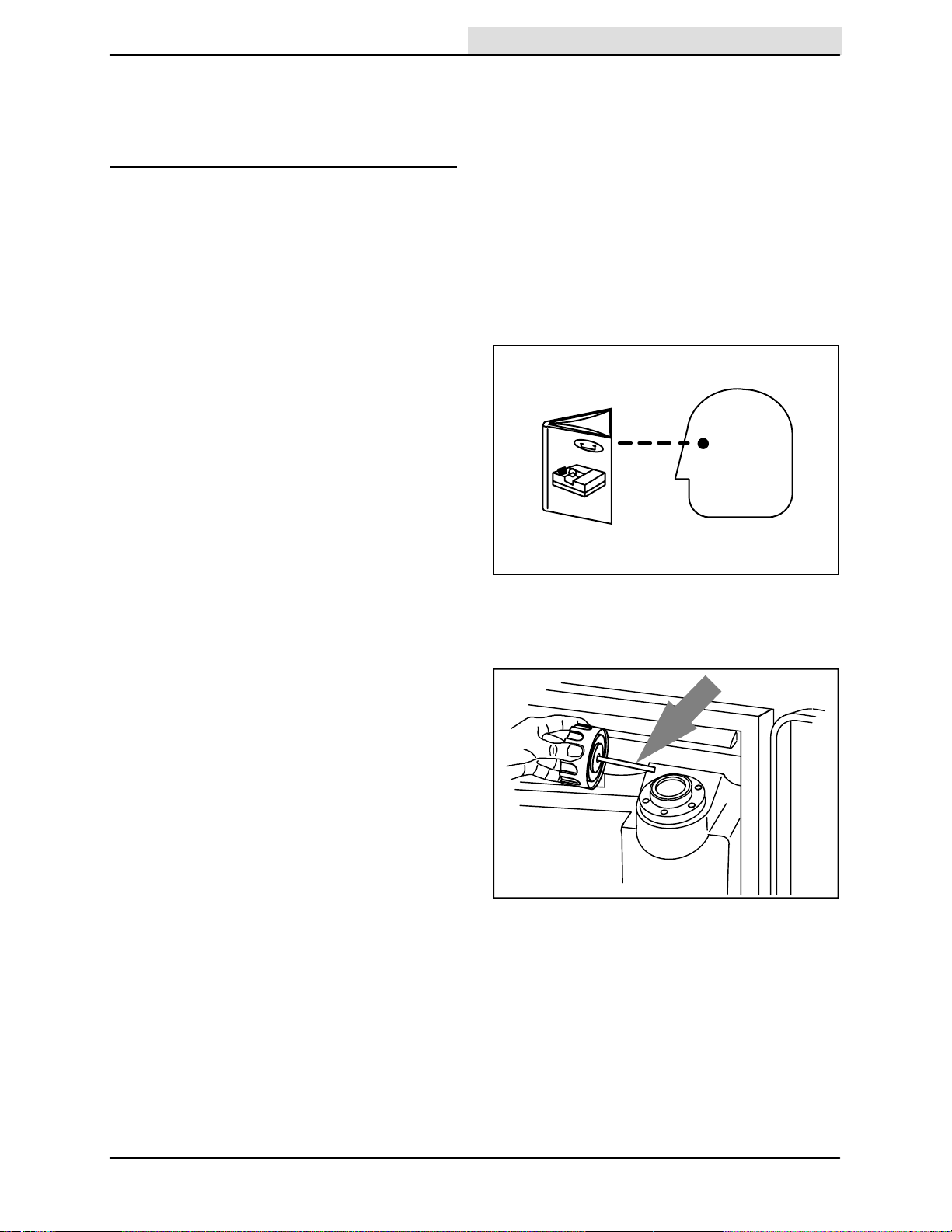
Read this manual carefully before operating
this machine.
FOR SAFETY: Do not operate machine,
unless operation manual is read and
understood.
OPERATION
OPERATION
Check the machine for shipping damage.
Check to make sure machine is complete
per shipping instructions.
Check the hydraulic fluid level in the
hydraulic reservoir.
After the first 50 hours of operation, follow
the recommended procedures stated in the
MAINTENANCE CHART.
Keep your machine regularly maintained by
following the maintenance information in this
manual. We recommend taking advantage
of a regularly scheduled service contract
from your TENNANT representative.
Order parts and supplies directly from your
authorized TENNANT representative. Use
the parts manual provided when ordering
parts.
07324
08218
355E MM306 (12–92)
5
OPERATION
Home
Find...
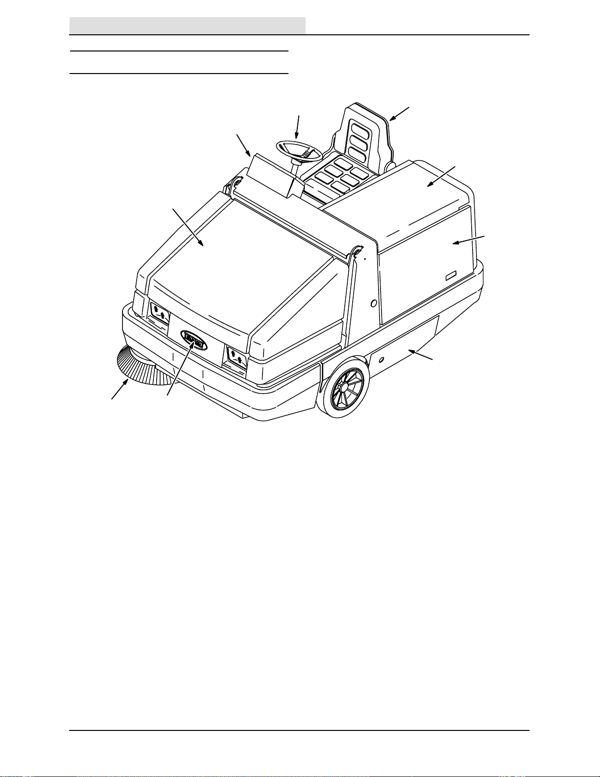
MACHINE COMPONENTS
B
I
F
A
C
D
E
H
G
07985
A. Operator Seat F. Hopper Cover
B. Steering Wheel G. Hopper Access Cover
C. Battery Cover H. Side Brush
D. Side Door I. Instrument Panel
E. Main Brush Access Door
6
355E MM306 (6--93)
CONTROL PANEL SYMBOLS
Home
Find...
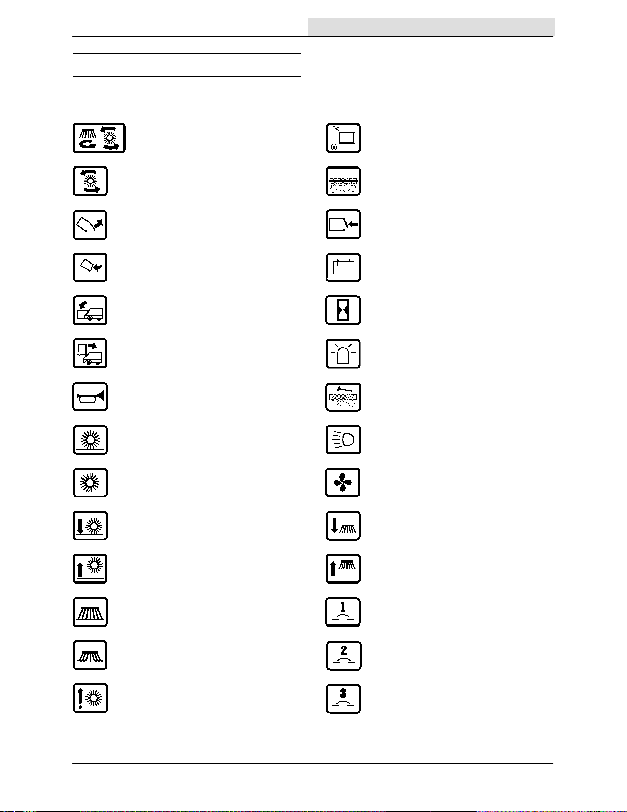
These symbols identify controls and displays on
the machine:
Main and Side Brushes On Hopper Temperature – Thermo Sentry
Main Brush On Filter Clogged
Hopper Door Open Hopper Door Closed
Hopper Door Close Battery
Hopper Down Hourmeter
OPERATION
Hopper Up Hazard Light
Horn Filter Shaker
Main Brush Down Pressure Light Operating Lights
Main Brush Down Pressure Heavy Fan
Main Brush Down Side Brush Down
Main Brush Up Side Brush Up
Side Brush Down Pressure Light Circuit Breaker 1
Side Brush Down Pressure Heavy Circuit Breaker 2
Main Brush Down Force Circuit Breaker 3
355E MM306 (12–92)
7

OPERATION
Home
Find...
Circuit Breaker 4
Circuit Breaker 5
Circuit Breaker 6
Circuit Breaker 7
Circuit Breaker 8
8
355E MM306 (12–92)
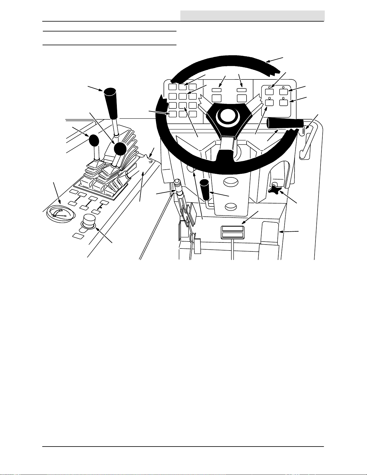
CONTROLS AND INSTRUMENTS
Home
Find...
OPERATION
U
P
O
L
I
G
F
Z
K
J
C
H
M
N
Y
D
R
V
B
Q
S
T
W
X
A
E
A. Directional Pedal N. Hopper Door Light
B. Brake Pedal O. Battery Discharge Indicator
C. Parking Brake Lever P. Hourmeter
D. Power Kill Switch Q. Hazard Light Switch (Option)
E. Horn Button R. Filter Shaker Switch
F. Main Brush And Side Brush Lever S. Operating Light Switch
G. Hopper Door Lever T. Vacuum Fan Switch
H. Hopper Lift Lever U. Steering Wheel
I. Main Brush Position Lever V. Side Brush Position Lever
J. Main Brush Down Pressure Knob W. On-Off Switch
K. Hopper Temperature Light -- X. Side Brush Down Pressure Knob
Thermo Sentryt Y. Steering Column Tilt Lever
L. Main Brush Shut Down Light Z. Brush Pressure Gauge
M. Clogged Filter Light
08219
355E MM306 (3-- 96)
9
OPERATION
Home
Find...
OPERATION OF CONTROLS
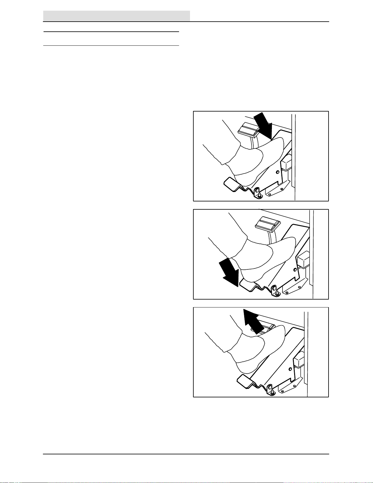
DIRECTIONAL PEDAL
The directional pedal controls direction of travel
and the propelling speed of the machine. You
change the speed of the machine with the
pressure of your foot; the harder you press the
faster the machine travels.
Forward: Press the top of the directional pedal
with the toe of your foot.
Reverse: Press the bottom of the directional
pedal with the heel of your foot.
Neutral: Take your foot off the directional pedal
and it will return to the neutral position.
NOTE: When changing direction from forward to
reverse using the directional pedal, the machine
will move a short distance forward before
changing direction. Use the brakes to stop the
machine.
08225
08226
FOR SAFETY: When using machine, use
brakes to stop machine.
10
08227
355E MM306 (12–92)
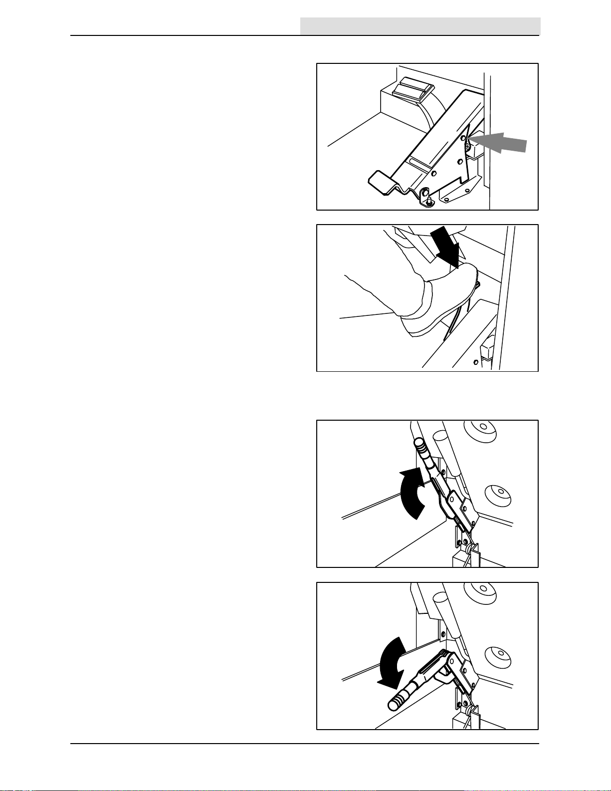
DIRECTIONAL PEDAL TOE ANGLE (OPTION)
Home
Find...
The directional pedal toe angle allows you to
adjust of the pedal toe angle. Remove the clevis
pin, move the top of the pedal to the angle
needed, and slide the clevis pin through the
adjustment holes.
OPERATION
BRAKE PEDAL
The brake pedal stops the machine.
Stop: Take your foot off the directional pedal and
let it return to the neutral position. Step on the
brake pedal.
PARKING BRAKE LEVER
The parking brake lever sets and releases the
front wheel brakes.
Set: Pull the parking brake lever up.
FOR SAFETY: Before leaving or
servicing machine; stop on level
surface, set parking brake, turn off
machine and remove key.
08292
08234
Release: Push the parking brake lever down.
355E MM306 (12–92)
08224
08223
11

OPERATION
Home
Find...
HORN BUTTON
The horn button operates the horn.
Sound: Press the button.
BRUSH PRESSURE GAUGE
The brush pressure gauge shows the pressure of
the main brush against the floor. The needle
should be in the green zone. If the needle is in the
red zone, reduce the main brush pressure with
the main brush pressure knob.
NOTE: The brush pattern should be 50 to 75 mm
(2.0 to 3.0 in).
08220
08221
12
355E MM306 (12–92)
MAIN BRUSH AND SIDE BRUSH LEVER
Home
Find...
The main brush and side brush lever controls the
main brush and side brush rotation.
Main Brush and Side Brush On: Push the main
brush and side brush lever into the On position.
Main Brush and Side Brush Off: Pull the main
brush and side brush lever into the middle
position.
OPERATION
07773
Main Brush On: Pull the main brush and side
brush lever into the On position.
NOTE: Always raise the main brush when the
machine is not being operated for some time. This
prevents the main brush from getting a flat spot.
07774
07775
355E MM306 (12–92)
13
OPERATION
Home
Find...
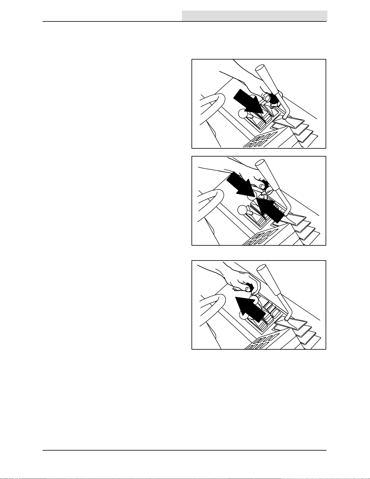
HOPPER DOOR LEVER
The hopper door lever opens and closes the
hopper door. Open the hopper door when
sweeping. Close the hopper door when emptying
the hopper to control debris and dust.
Open: Push the hopper door lever into the Open
position and leave it there.
Hold: Release the hopper door lever into the
middle position.
07776
Close: Pull and hold the hopper door lever into
the Close position.
NOTE: The hopper door will not close if the main
brush and side brush are operating.
07777
07778
14
355E MM306 (5–94)
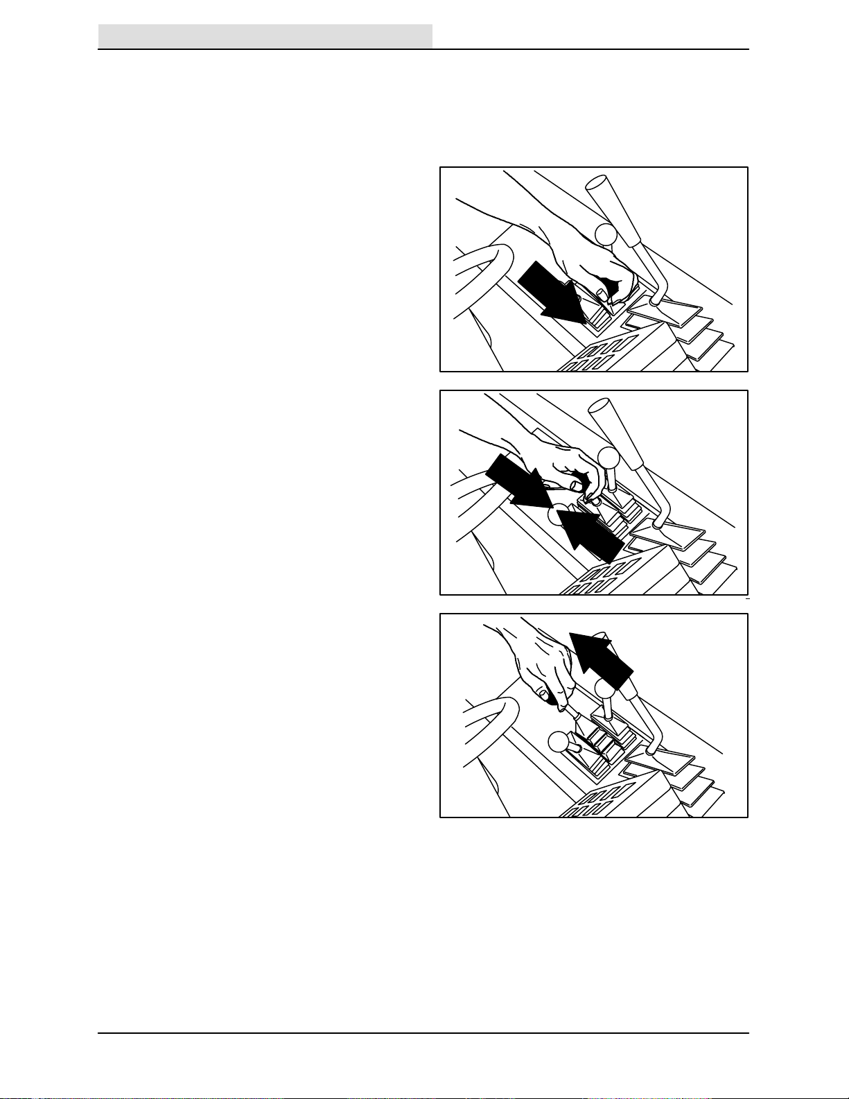
HOPPER LIFT LEVER
Home
Find...
The hopper lift lever raises and lowers the hopper.
Up: Pull and hold the hopper lift lever into the Up
position.
WARNING: Raised hopper may fall.
Engage hopper support bar.
NOTE: The hopper will not raise if the main brush
and side brush are operating.
Hold: Release the hopper lift lever up and into the
middle position.
OPERATION
07779
Down: Push and hold the hopper lift lever into the
Down position.
07780
07781
355E MM306 (12–92)
15
OPERATION
Home
Find...
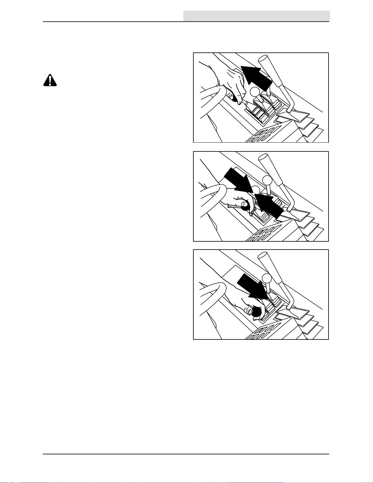
MAIN BRUSH POSITION LEVER
The main brush position lever lowers and raises
the main brush.
Down: Pull the main brush position lever back
and to the left into the Down position.
Up: Pull the main brush position lever all the way
back and to the right into the Up position.
07782
07784
16
355E MM306 (12–92)
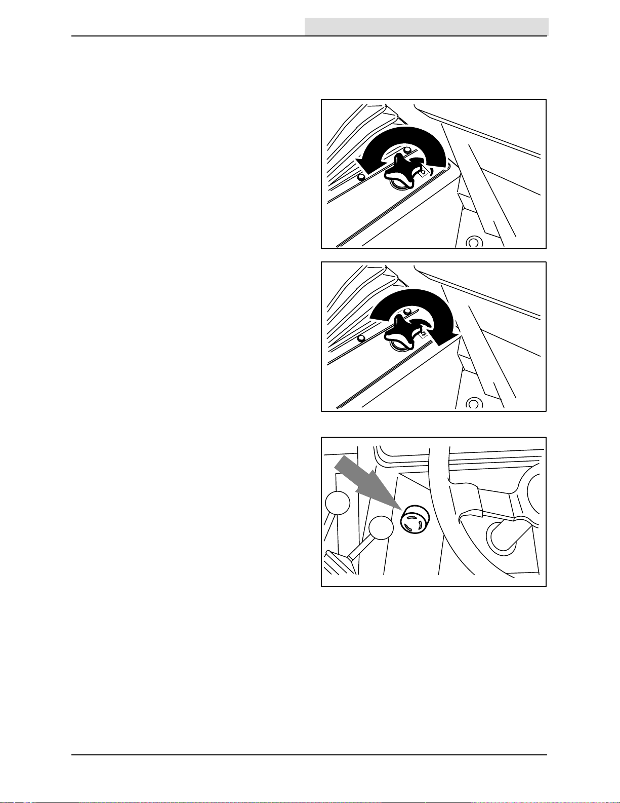
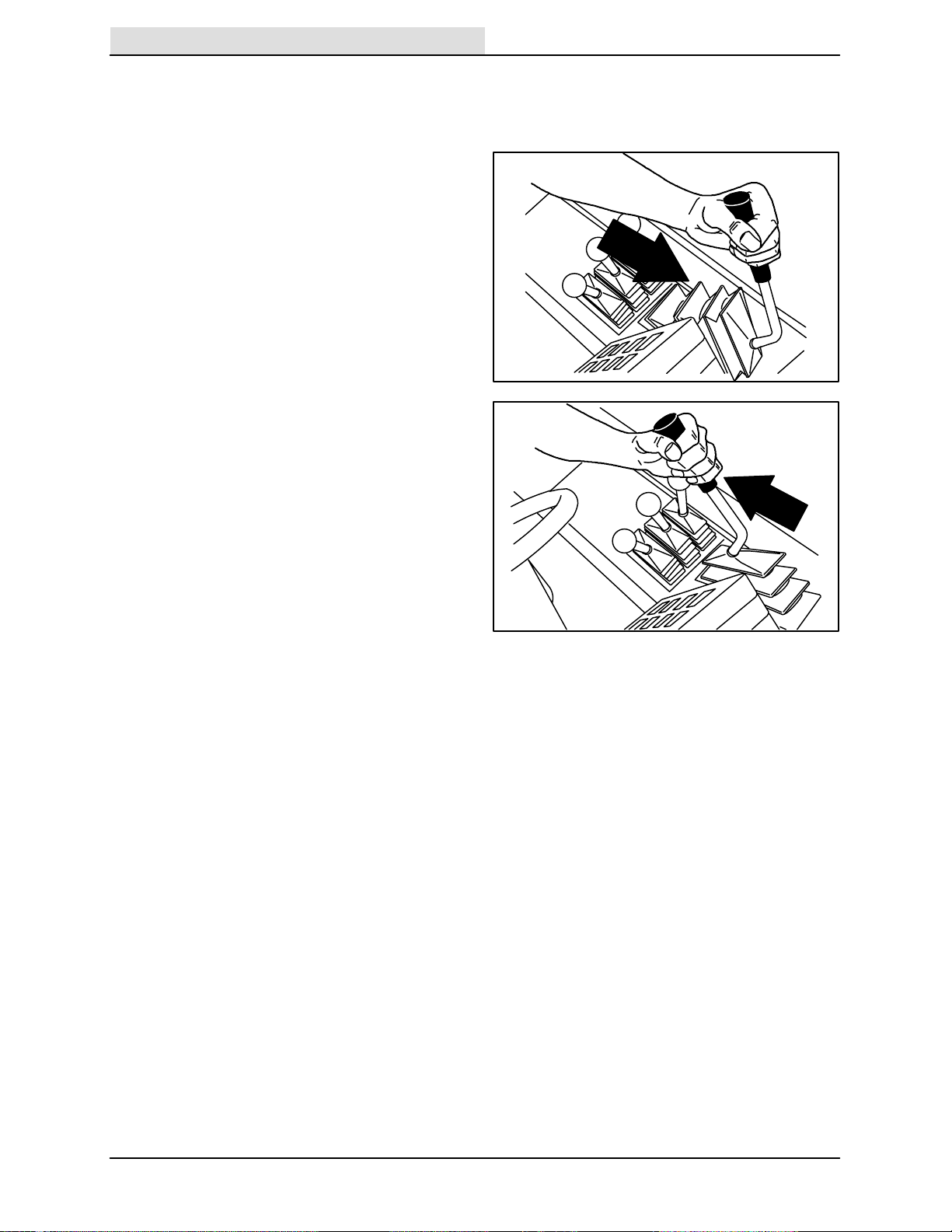
MAIN BRUSH DOWN PRESSURE KNOB
Home
Find...
The main brush down pressure knob changes the
main brush contact with the sweeping surface.
Heavy: Turn the main brush down pressure knob
counter-clockwise.
Light: Turn the main brush down pressure knob
clockwise.
OPERATION
07787
POWER KILL SWITCH
The power kill switch halts all power to the
machine.
Halt: Hit the power kill switch.
Restart: Turn the power kill switch to the right to
release the switch. Turn the on-off switch key fully
clockwise, then release the switch key.
07788
08237
355E MM306 (12–92)
17
OPERATION
Home
Find...
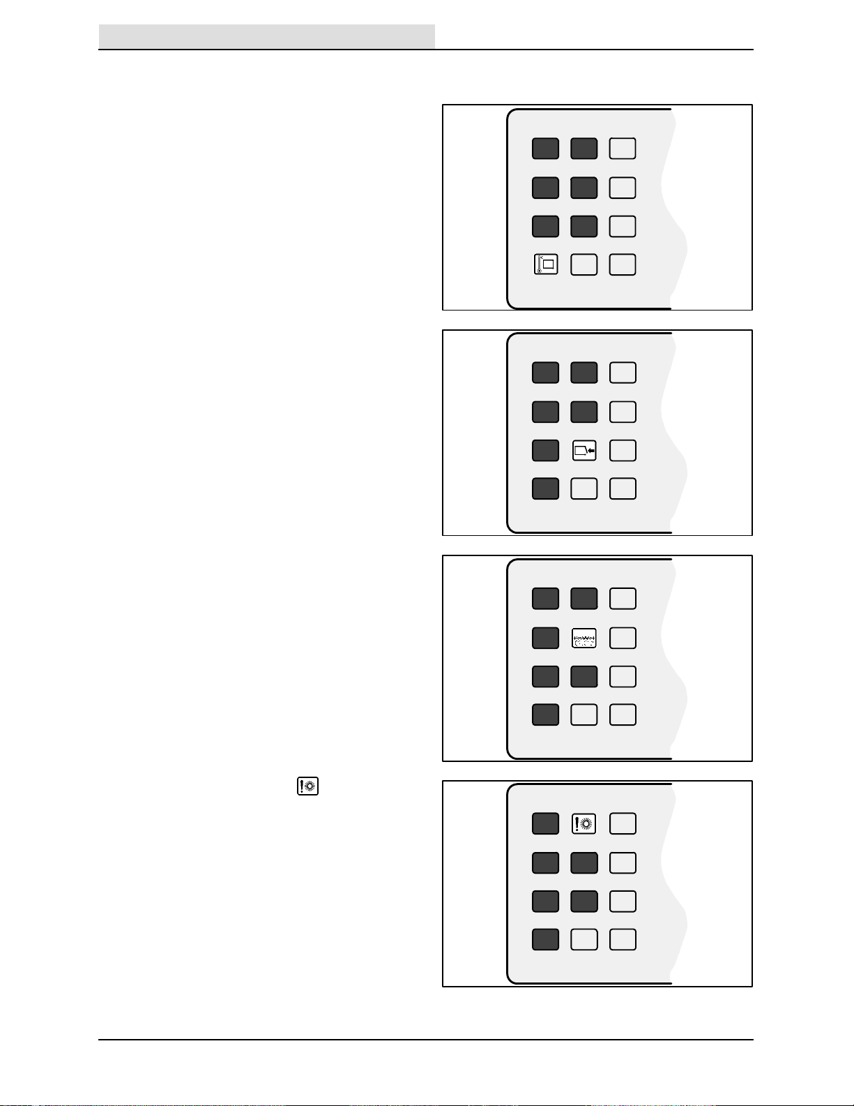
HOPPER TEMPERATURE LIGHT – THERMO
SENTRY
The hopper temperature light comes on when
there is too much heat in the hopper, possibly
from a fire. The Thermo Sentry will stop the
vacuum fan.
The Thermo Sentry has to be reset manually,
see THERMO SENTRY in MAINTENANCE.
HOPPER DOOR LIGHT
The hopper door light comes on when the hopper
door is closed. Make sure the hopper door is open
and the hopper door light is off, before sweeping
with the machine.
CLOGGED FILTER LIGHT
The clogged filter light comes on when the hopper
dust filter is clogged.
To clean the filter, press the filter shaker switch. If
the clogged filter light remains lit, manually clean
the hopper dust filter. See HOPPER DUST
FILTER in MAINTENANCE.
07760
07763
MAIN BRUSH SHUT DOWN LIGHT
The main brush shut down light comes on
when there is excessive down pressure for the
main brush, or there is a problem with the main
and side brush hydraulic motor circuit. The brush
pressures can be reduced with the main brush
and side brush pressure knobs.
18
07762
07761
355E MM306 (12–92)
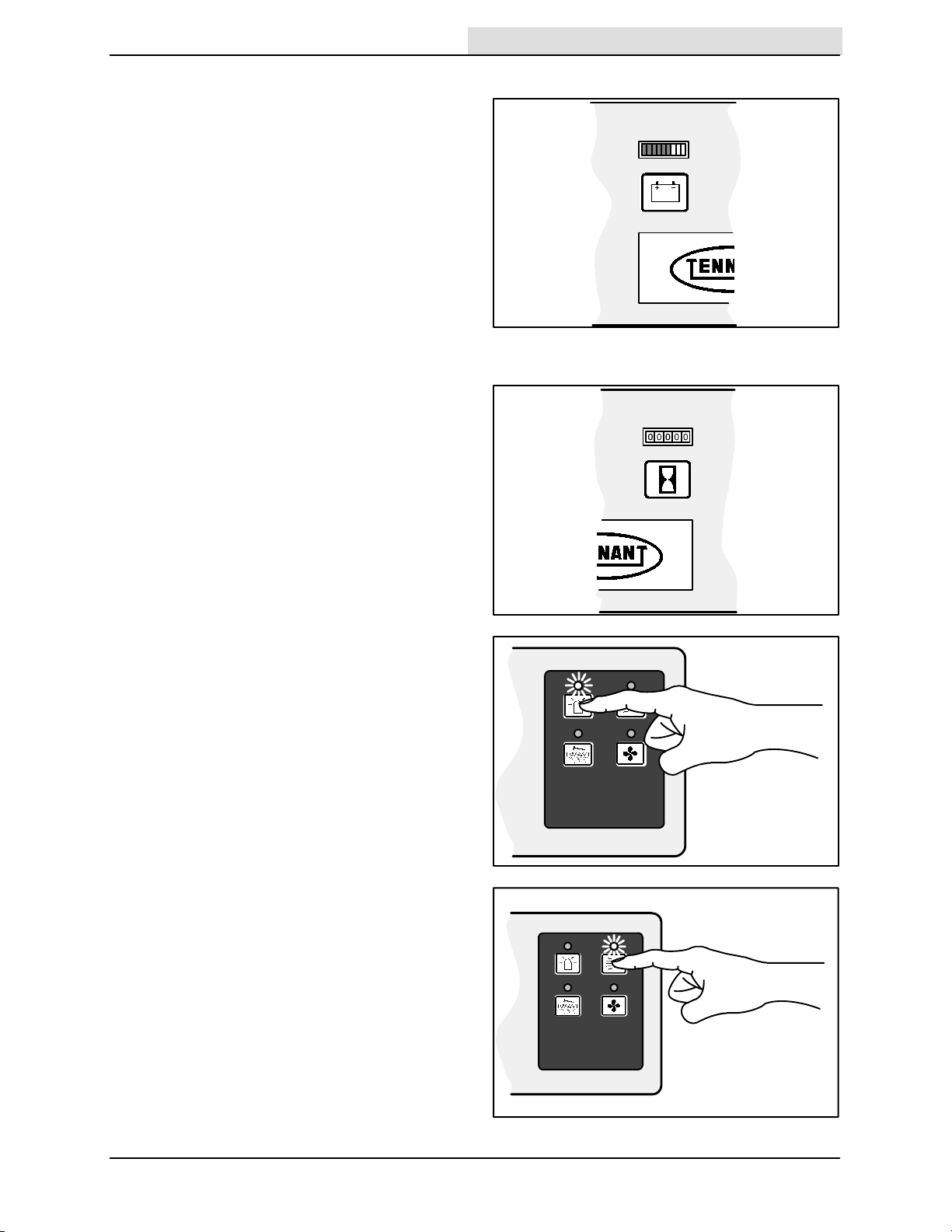
BATTERY DISCHARGE INDICATOR
Home
Find...
The battery discharge indicator shows the charge
level of the batteries with a segmented LED light.
When the batteries are fully charged, all of the
segments are lit. As the batteries discharge, the
segments shut off.
Recharge the batteries when the last two
segments are flashing.
NOTE: The reading of the battery discharge
indicator is not accurate when the machine is first
powered on. Operate the machine a few minutes
before reading the charge level of the batteries.
HOURMETER
The hourmeter records the number of hours the
machine has been operated. Use this information
to determine machine maintenance intervals.
OPERATION
08233
HAZARD LIGHT SWITCH (OPTION)
The hazard light switch powers on and off the
hazard light.
On: Press the hazard light switch. The indicator
light above the switch will come on.
Off: Press the hazard light switch. The indicator
light above the switch will go off.
OPERATING LIGHTS SWITCH
The operating lights switch powers on and off the
headlights and taillights.
On: Press the operating lights switch. The
indicator light above the switch will come on.
Off: Press the operating lights switch. The
indicator light above the switch will go off.
07765
08228
355E MM306 (12–92)
08230
19
OPERATION
Home
Find...
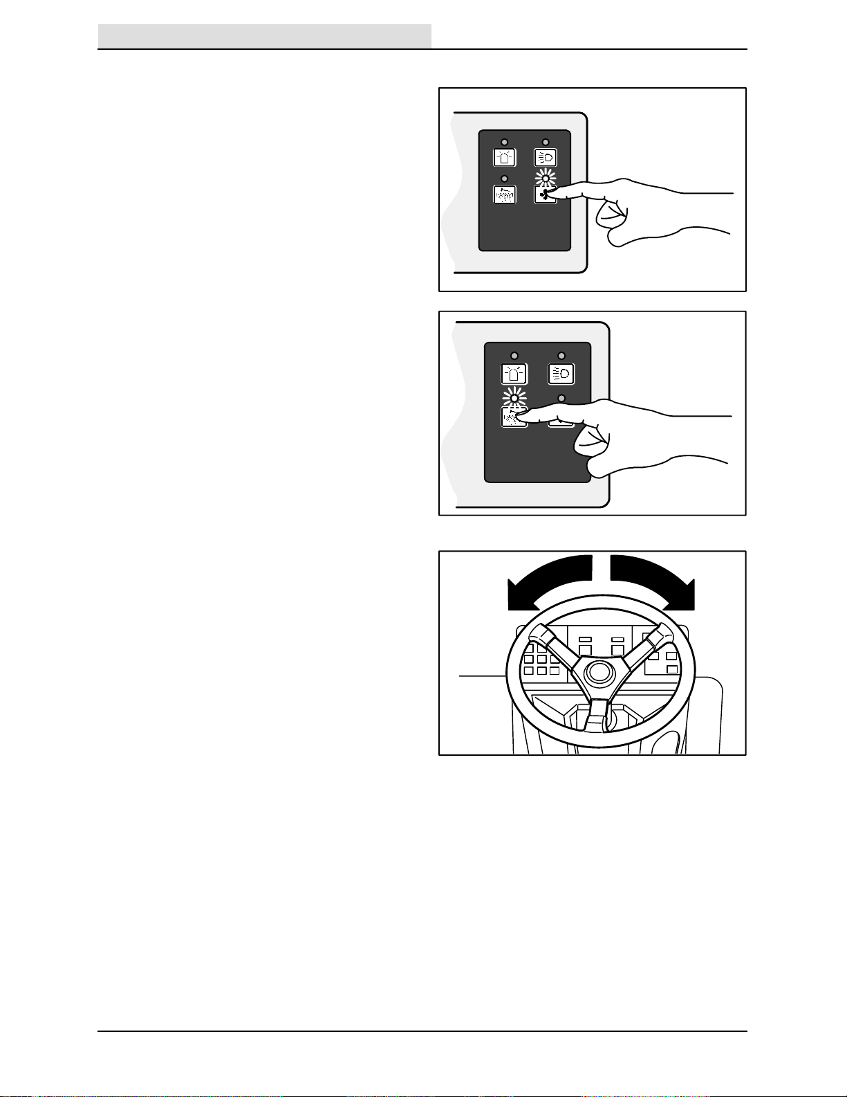
VACUUM FAN SWITCH
The vacuum fan switch starts and stops the
vacuum fan.
Start: Press the vacuum fan switch. The indicator
light above the switch will come on.
Stop: Press the vacuum fan switch. The indicator
light above the switch will go off.
FILTER SHAKER SWITCH
The filter shaker switch starts the hopper dust
filter shaker. The shaker automatically operates
for 40 seconds.
Start: Press the filter shaker switch. The indicator
light will remain on while the filter shaker is
operating.
NOTE: The vacuum fan shuts off while the filter
shaker is operating.
STEERING WHEEL
The steering wheel controls the machine’s
direction. The machine is very responsive to the
steering wheel movements.
Left: Turn the steering wheel to the left.
Right: Turn the steering wheel to the right.
08231
08229
20
07801
355E MM306 (12–92)
 Loading...