

Page 1
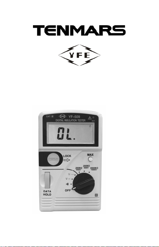
DIGITAL INSULATION TESTER
YF
-
509
OPERATING
TENMARS ELECTRONICS CO., LTD
MANUAL
HB2YF5090000
Page 2

CONTENTS
1. FEATURES..................................................... 3
2. SPECIFICATIONS......................................... 4
2-1General Specifications .................................. 4
2.2Electrical Specifications:................................ 6
3. EXTERIOR FEATURES ................................ 8
4. MEASUREMENT........................................... 9
5. BATTERY REPLACEMENT......................... 12
6. SYMBOL/ABBREVIATION
EXPLANATION............................................ 13
7. PRECAUTIONS........................................... 13
8. IMPORTANT RECOMMENDATIONS.......... 15
Page 3

YF-509
Thank you for your patronage. Before using
this insulation meter, please carefully read
the instructions below to allow proper
operation, minimize damage and getting
the best performance from this instrument.
1. FEATURES
Measures high insulation resistance
(0.1MΩ~2000MΩ), manual range , of
200MΩ / 250V,200MΩ / 500V and
2000MΩ / 1000V.
Measures DC voltage (0 V~1000V), AC
Voltage
( 0V ~ 750V).
The unit has select able long duration
and momentary operation switches for
high resistance measurements.
Has a DATA HOLD switch to hold LCD
readings.
Has a Maximum Reading Hold function.
3
Page 4

YF-509
2. SPECIFICATIONS
2-1 General Specifications
Display :
3 1/2 digit LCD that indicates values up
to 1999, units, decimal point and
symbols.
Polarity indication : Automatically
displays “ - “ symbol during negative
input.
Zero adjustment : Automatic zeroing.
Overload indication :
Display the highest “OL” at left side.
Low battery indication :
Replace battery as LCD displays “ “.
Sampling rate : 2.5 times/second.
Power supply : 1.5V x 8 NEDA 15F IEC
R6 JIS UM-3
Battery life : 100 hours
4
Page 5

YF-509
Note:
Power consumption is greatest when
operating in the 250V, 500V and 1,000V
ranges or when measuring high insulation
resistance. Battery life will be reduced if
operation is frequently in these ranges.
Operation height : 2000M under the
elevation above sea level.
Installation categoriesⅢ. Double and
Reinforce Insulation .
Operation environment : for indoor use ,
pollution degree 2.
Operating temperature and humidity :
0℃~40℃at less than 80% RHD.
Storage temperature and humidity :
-10℃~60℃below 70% RH.
Dimensions and weight :
160 x 100 x 52mm, about 480g (incl.
Battery).
Accessories : Ohm probe -1 set, case -1
pcs), batteries- 8 PCs and operation
manual.
5
Page 6
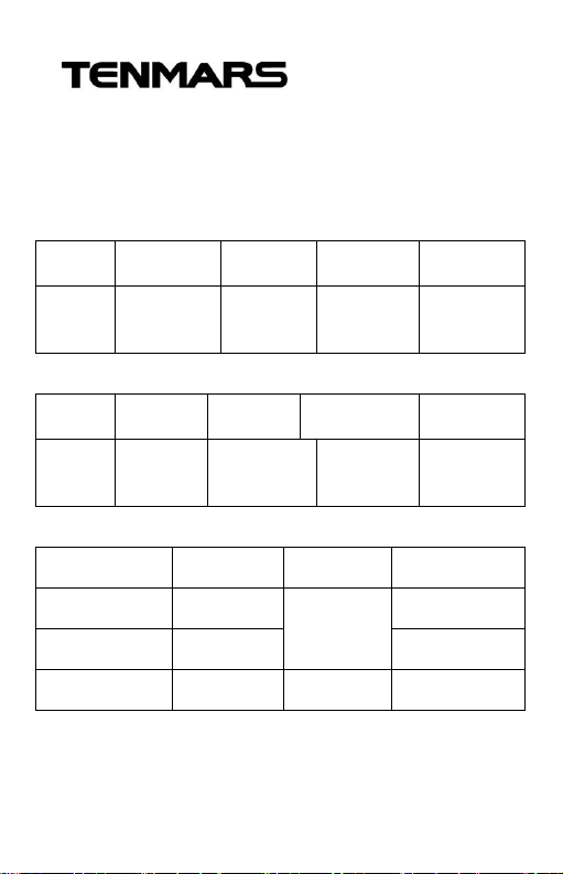
2.2 Electrical Specifications:
(23℃±5℃, below 80%RH ).
Accuracy : ±(. . . % reading +. . . digits)
DC Voltage
Range Resolution Accuracy
DCV 1V
±(0.5%
+1)
AC Voltage
Range Resolution Accuracy
DCV 1V
±(0.8%
+4)
Insulation High-resistance
Range Resolution Accuracy Tolerance
Input
Impedance
10MΩ
Input
Impedance
10MΩ
YF-509
Overload
Protection
DC 1000V
AC 750V
rms
Overload
Protection
DC 1000V
AC 750V
rms
200M/250V
200M/500V
2000M/1000
0.1MΩ
±(3%+3)
0.1MΩ
1 MΩ ±(3%+5)
6
0.4mA max
0.9mA max
1.7mA max
Page 7
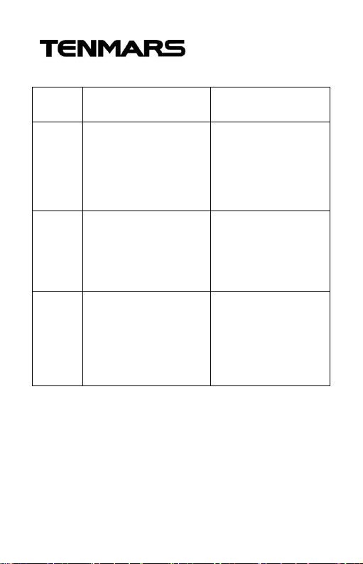
Measurement Voltage
range,
Range
250V/
50MΩ
500V/
1000MΩRated voltage ±10%
1000V/
2000MΩRated voltage ±10%
Terminal Measurement
open Voltage
Rated voltage ±10%
YF-509
Supported Range
Terminal Voltages
When the resistance
is in the 1MΩrange,
the rated voltage
should reach up to
90%.
When the resistance
is in the 20MΩ
range,the rated
voltage
When the resistance
is in the 50MΩ
the rated voltage
should reach up to
90%.
7
Page 8
YF-509
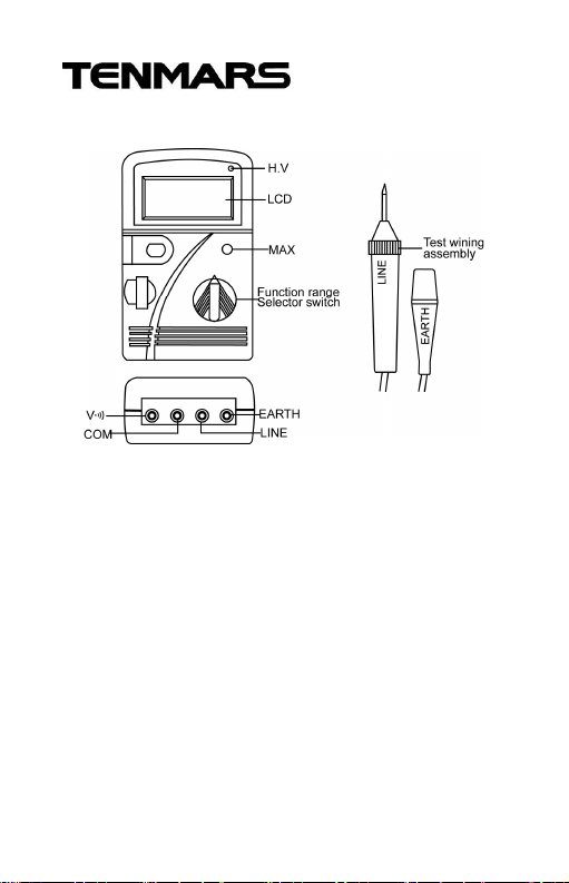
3. EXTERIOR FEATURES
(1). Liquid crystal display (LCD) : Displays
measurement readings, all numerical
units, symbols and range indications.
(2). H.V : High voltage output indication.
(3). LOCK switch : Used for extended
duration MΩ measurements.
(4). PUSH switch : Used for momentary
duration MΩ measurements.
(5). D-HOLD : Holds displayed readings.
(6). Function range selector switch :
Meter function range selection
8
Page 9
YF-509
indication.
(7). V / test socket : Positive input
terminal for AC/DC voltages and
continuity testing.
(8). EARTH test socket: Positive input
terminal for high voltage output MΩ
resistance measurements.
(9). Test wiring assembly.
(10). MAX : Lock up max. Value of LCD.
(11). LINE test socket : Negative input
terminal for m resistance
measurements.
(12). COM test socket : For connection of
negative input terminal. AC/DC
Voltages and continuity tests.
4. MEASUREMENT
Direct Current Voltage (DCV) and Alternating
Current Voltage (ACV) measurement.
(1). Select the V or V~
(2). Insert the red test probe into the " V/
" socket and the black test probe
into the "COM" socket.
9
Page 10

YF-509
(3). Measure voltage with the two tips of the
test probes (by contacting a test
circuit).
(4). The value of the voltage\read will be
displayed on the LCD screen.
Continuity Test
(1). Insert the red test probe into the " V/
" socket and the black test probe into
the "COM" socket.
(2). Move the function switch to the " "
range.
(3). Place the probes in series with the
circuit (a pure resistance circuit) to be
tested.
(4). A continuous beeps will sound when
the resistance is less than 80Ω and the
resistance value displayed on the LCD
screen.
Note :
Continuity tests should only be conducted on
a purely resistive circuit having no voltage or
current present.
10
Page 11

YF-509
High Resistance Insulation Test
(1). Insert the red test probe into the "LINE"
socket and the black test probe into the
"EARTH" socket.
(2). Turn the function switch to the
200MΩ/250V,200MΩ/500V or
2000MΩ/1000V position (according to
the voltage level).
(3). Connect the red test probe (LINE) to
center conductor of the line to be tested
and connect the black test probe
(EARTH) to the insulator surface.
(4). Press the "PUSH" switch to allow
measurement of the high voltage
output. If measurement is to be
conducted for an extended duration,
move the "LOCK" switch from left to
right to enter this testing mode.
(5). The resistance reading will be
displayed on the LCD screen.
11
Page 12

YF-509
5. BATTERY REPLACEMENT
The meter is powered by 1.5V battery
x8pcs (NEDA 15F IEC R6 JIS UM-3). use the
fowling procedure to replace the battery:
(1). Move the function switch to the "OFF"
position.
(2). Use a screw driver to unfasten the
screws on the battery cover and
remove the cover.
(3). Take out the old batteries and replace
with new batteries, taking care to note
the correct polarity.
(4). Re-install the battery cover and tighten
the holding screws.
12
Page 13
YF-509
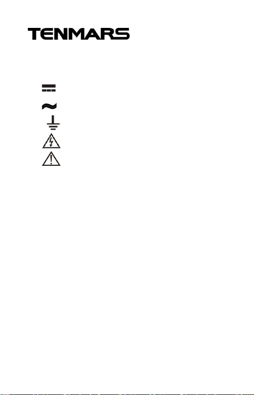
6. SYMBOL/ABBREVIATION
EXPLANATION
1) : indicates direct current.
2) : indicates alternating current.
3) : indicates ground.
4) : indicates double insulation.
5) : indicates high voltage hazard.
7. PRECAUTIONS
Extreme caution should be exercised
when taking measurements under the
following situations:
(1). When measuring high voltages in
excess of 20 volts.
(2). Avoid physical contact when measuring
AC power.
(3). Avoid measuring voltage and current in
humid or wet environments.
13
Page 14

YF-509
(4). Never use meter test probes (the metal
section) and other accessories that are
in abnormal condition. This includes
damage, bending, breakage,
attachment of foreign objects and
unobservable internal damage.
(5). Avoid contacting exposed metal
(conductive) parts, including the tested
points, sockets, fasteners and wiring.
(6). Always insulate yourself from circuits
being measured.
(7). Never install a fuse that is of larger
capacity than the unit originally used in
the meter or use a replacement fuse
that does not meet the recommended
specifications.
(8). Never operate the meter where
explosive or flammable gas (or material)
are present or in environments having
a high dust content.
14
Page 15

YF-509
8. IMPORTANT
RECOMMENDATIONS
This electrical meter is a high precision
instrument.
To maintain full accuracy, users must not
exceed the previously described
specifications regarding operation and
storage. Other recommendations include:
(1). Do not measure voltages that exceed
DC 1000V and AC 750V rms.
(2). For maintenance, use a soft dry cloth
for cleaning the unit. Never use a wet
cloth, solvents or water, etc.
(3). Remove the batteries if the unit will not
be operated for an extended length of
time. Also, do not store the unit in areas
of high temperature and humidity.
15
Page 16

Professional Electrical and
Environment Test & Measurement
Instruments:
Battery Capacity / Impedance Tester, TACHO
Meter ,LED light meter,Temperature & Humidity
meter ,Infrared Thermometer,Sound level
meter ,Light meter, EMF meter, UV Light meter,
RF meter, Hot wire Anemometer, CO meter
Anemometer, Lan cable tester, CO2meter,
Solar power meter, Radiation meter,
Clamp meter, Multimeter, Phase Rotation test,
Digital Insulation tester
Our products of high quality are selling
well all over the world
TENMARS ELECTRONICS CO., LTD
6F, 586, RUI GUANG ROAD, NEIHU,
TAIPEI 114, TAIWAN.
E-mail: [email protected]
http://www.tenmars.com
 Loading...