

Page 1
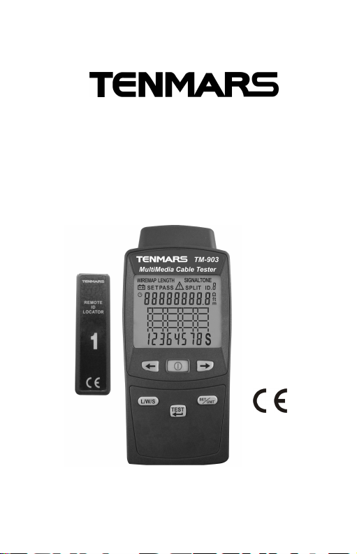
User Manual
Multi Media Cable Tester
HB2TM90200
1
1
TM-901N/TM-902/TM-903
TENMARS ELECTRONICS CO., LTD
Page 2

Page 3

Table of Contents
1 Introduction......................................................1
2 Safety Precaution.............................................1
3 The verifier does the following:.........................2
4 Display Features..............................................3
5 Multi Media Cable Tester Features...................4
6 Testing TwistedPair Cabling............................5
7 Twisted Pair Test Results.................................6
Opens .............................................................6
Shorts..............................................................7
Miswires..........................................................7
Split Pair..........................................................8
8 Length measures.............................................9
9 SIGNALTONE measures(TM-903).................10
10 Using Multiple Remote ID Locators................11
11 Auto power on and off setting mode...............12
12 Backlight on or offsetting mode.....................13
13 Changing Memory Number / Default Category
/Types(UTP/STP)/Calibrating Length
Measurements Value Parameter Options.......14
14 Checking the LCD and Software Version.......16
15 Battery Replacement .....................................17
16 Options and Accessories................................17
17 End of life.......................................................17
18 Specifications.................................................18
Page 4
TM-901N/TM-902/TM-903
1 Introduction
The TM-902/TM-903 Multimedia Cable
Tester (TM-901N LAN Cable Tester)is a
hand-held test instrument that lets you verify
and troubleshoot the Lan cable of twisted
pair.
2 Safety Precaution
CAUTION
Be extremely careful for the
following conditions while measuring
Do not operate the meter under the
environment with explosive gas (material),
combustible gas (material) steam or filled
with dust.
In order to avoid reading incorrect data,
please replace the battery immediately
when the symbol “ ” appears on the
LCD.
In order to avoid the damage caused by
contamination or static electricity, do not
touch the circuit board before you take
any adequate action.
Operating Environment: Indoors use. This
instrument has been designed for being
1
Page 5

TM-901N/TM-902/TM-903
used in an environment of pollution
degree 2.
Operation Altitude: Up to 2000M.
EMC: EN61326-1(2006),
IEC 61000-4-2(2008,
IEC 61000-4-3(2006) + (2007).
3 The verifier does the following:
Detects opens, shorts, miswires and split
pairs on twisted pair cabling.
Displays graph wiremap , opens, shorts,
miswires, split pairs, and the remote ID
number all on one screen.
Identify remote ID number only one pair.
Measures length.
Using multiple remote ID up to 8 locators.
Low battery detector “ ”.
Auto backlight.
Auto power off.
2
Page 6
TM-901N/TM-902/TM-903
4 Display Features
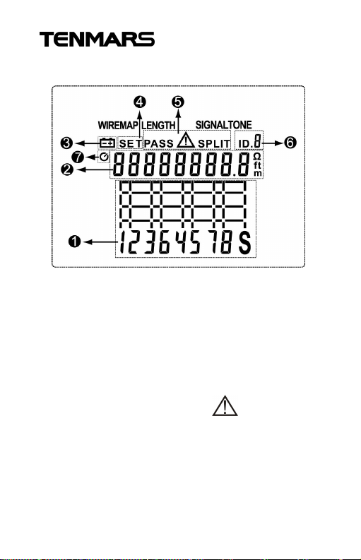
1.Displays graph wiremap , opens,
shorts, miswires, split pairs.
2. Displays Length and Unit.
3. Lower battery indication.
4. Enter the SETUP mode symbol.
5. Result displays, Pass, , split.
6. Displays remote ID number.
7. Auto power off
3
Page 7
TM-901N/TM-902/TM-903
5 Multi Media Cable Tester Features
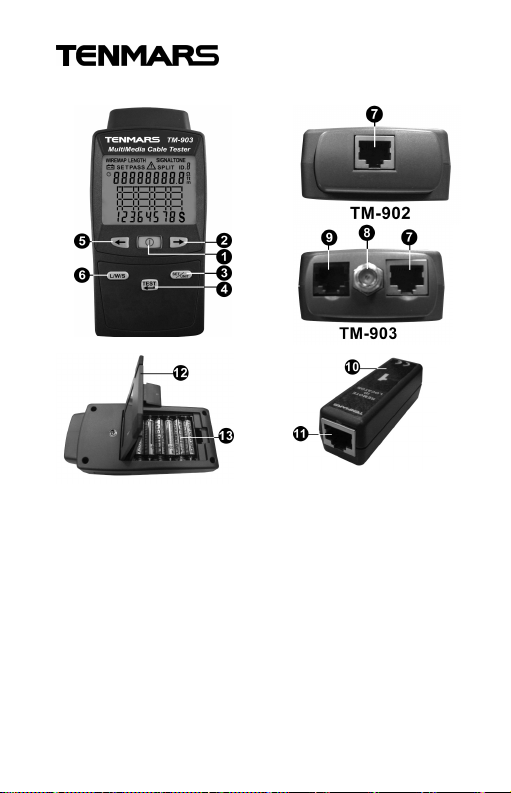
1. Power Key.
2.Setup function right
Key.
3.Setting Key and Unit
select Key
4.Test Key and Enter
Key.
5.Setup function left
Key.
6.Length and wiremap
and signal-tone
function key
7. RJ-45 connectorsocket.
8. F-Connector .(TM-903)
9. RJ-11 connector
socket.(TM-903)
10.Remote ID locator.
11.RJ-45 connector socket
of remote ID locator.
12.Tilt-stand.
13.Battery cover.
4
Page 8
TM-901N/TM-902/TM-903
6 Testing Twisted Pair Cabling
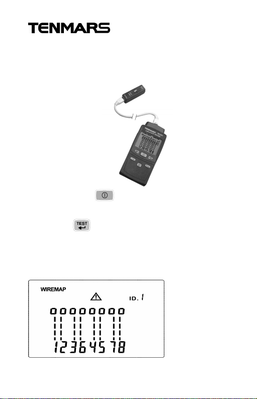
1. Connect the meter and remote ID locator
to the cabling as shown in Figures.
2. Press the key to power on.
(TM-902/903)
3. Press key to measures wiremap and
Remote ID Locators detect.
4. Display show some testing option as
shown in Figures.
5
Page 9
TM-901N/TM-902/TM-903
7 Twisted Pair Test Results
The following figures show typical test results
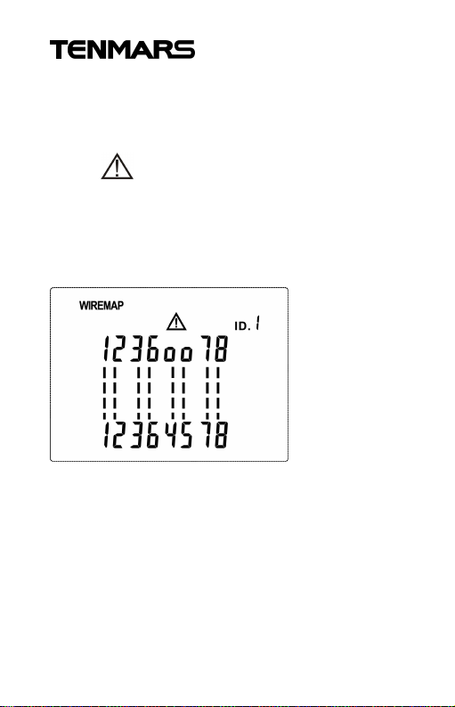
for twisted pair cabling. Any error occurs will
show symbol on LCD.
Opens
Figure shows an open pair wire 4 and 5.
6
Page 10
TM-901N/TM-902/TM-903
Shorts
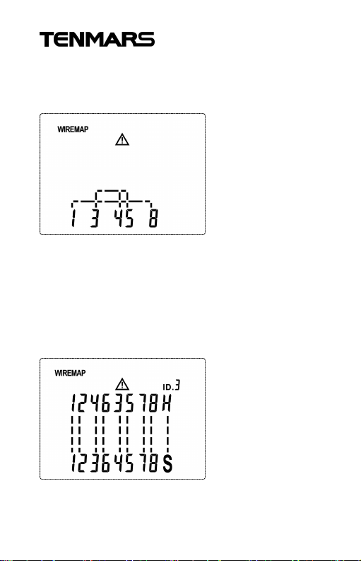
Figure shows tow short between wires 3, 4
and 5, another 1 and 8.
※ When shorted occur, the verifier maybe
not show open and miswires.
Miswires
Figure shows that wires 3 and 4 are crossed.
The pin numbers order to indicate the fault.
7
Page 11
TM-901N/TM-902/TM-903
Split Pair
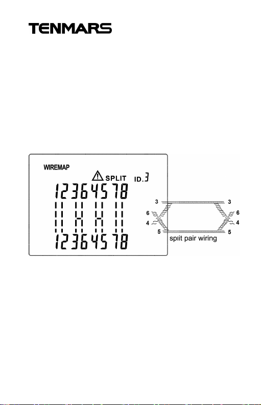
The following figure shows a split pair on 3, 6
and 4, 5. The split pair flashes to indicate the
fault. LCD will show “SPLIT” indicate.
In a split pair, continuity from end to end is
correct, but is made with wires from different
pairs. Split pairs cause excessive crosstalk
that interferes with network operation.
※ The spilt pair detects of cable must be at
least 5 meters (15ft) in length.
※ If one of open, short or miswires occurs,
the spilt pair detects won’t work.
8
Page 12
TM-901N/TM-902/TM-903
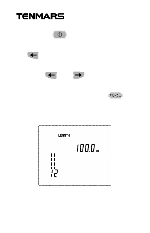
8 Length measures
1. Press the key to power on.
2. Press the L/W key(TM-901N/TM-902) or
key(TM-903) to switch to Length
(TM-903).
3. Press and Key to select
show length pairs 1~4.
4. In the display length. Press the key
to changing the length units, shown in
Figure.
9
Page 13
TM-901N/TM-902/TM-903
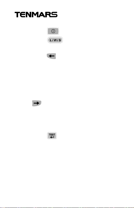
9 SIGNALTONE measures(TM-903)
1. Press the key to power on.
2. Press the key to switch to
SIGNALTONE.
3. Press the Key to select a different
tone sequence displayed as the
numbers 1~4 on LCD.
4. The function default continuity(LCD
display “C”)
5. If you want to changing, press
the Key to select continuity (LCD
display “C”) to changing one-shot(LCD
display “F”) ,you can selection numbers
1~8.
6. Press the key to enable or disable
out signal tone is cable tracing function.
Toner is cable tracing function that
assists intracking cables hidden in walls.
Ceilings, floors or patch panels by
generating four distinct multi-tone
signals that can be received by a cable
tracer. To trace a cable
10
Page 14
TM-901N/TM-902/TM-903
10 Using Multiple Remote ID
Locators
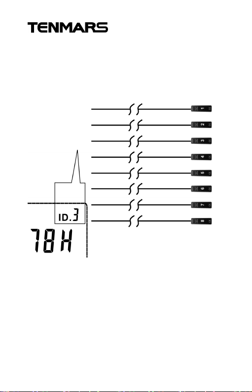
Using multiple remote ID locators helps you
identify multiple network cable connections,
as shown in Figure.
The display in Figure shows that the verifier
is connected to the cable terminated with
remote ID locator number 3.
11
Page 15
TM-901N/TM-902/TM-903
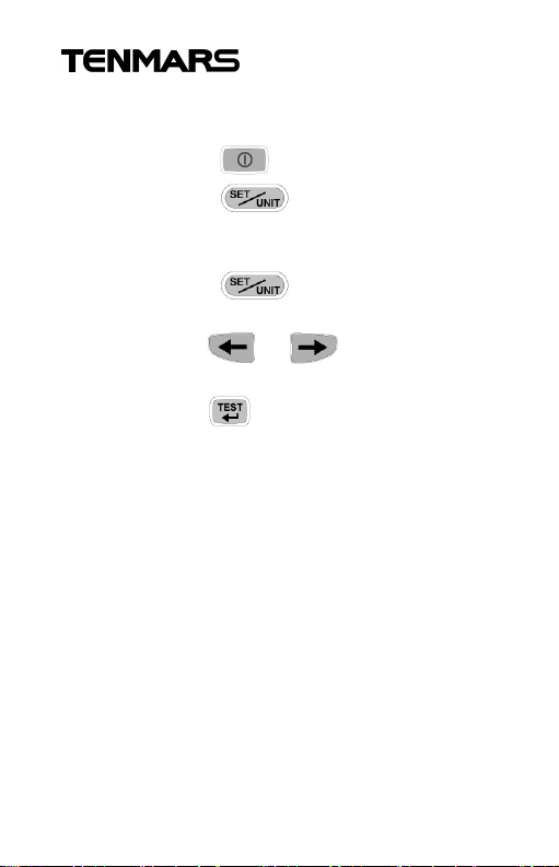
11 Auto power on and off setting
mode
1. Press the key to power on.
2. Press the key for more than 2
Second to enter Setting mode into
setting mode.
3. Press the key again to auto
power on or off setting.
4. Press the or key to change
ON or OFF.
5. Press the key to enter and exit
setting mode, shown in Figure.
.
12
Page 16
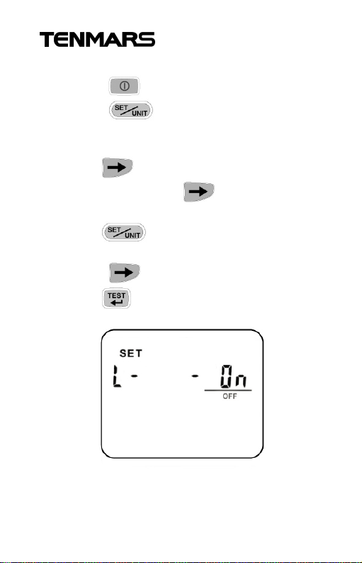
TM-901N/TM-902/TM-903
12 Backlight on or off setting mode
Press the key to power on.
Press the key for more than 2
Second to enter Setting mode into setting
mode.
Press the key setting to auto power on
or off setting Press the key to backlight
set
Press the key again to backlight
setting mod
Press the key to change ON or OFF.
Press the key to enter and exit setting
mode, shown in Figure.
13
Page 17
TM-901N/TM-902/TM-903
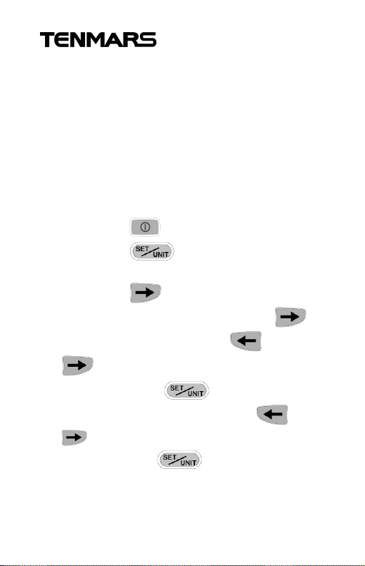
13 Changing Memory Number /
Default Category /Types(UTP/STP)
/Calibrating Length Measurements
Value Parameter Options
The meter to provide user self calibrate
memory use number 1 ~ 9. User can order
different cable type, category and length to
acquire measurements value parameter.
1. Press the key to power on.
2. Press the key more than 2
second to and setting mode.
3. Press the key setting to auto
power on or off setting Press the
key to backlight set Press and
key to select number zero from
No.0~9 . Press key again to
setting flashes number. Press and
key to select number zero from
No.0~9 . Press key to enter exit
setting mode,
14
Page 18
TM-901N/TM-902/TM-903
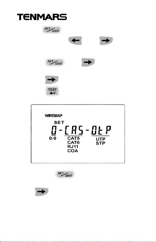
4.Press key into setting flashes cable
category, Press and key to
setting cat 5 or cat 6 ,( RJ11,COAX.TM-903).
5. Press key again to setting
flashes cable type.
6. Press key to select UTP or STP,
Press key toenter exit setting mode
shown in Figure.
7. Press the key more than 2
second to and setting mode. Press
the key again to select setting
flashes calibrating length measurements
value parameter.
15
Page 19
TM-901N/TM-902/TM-903
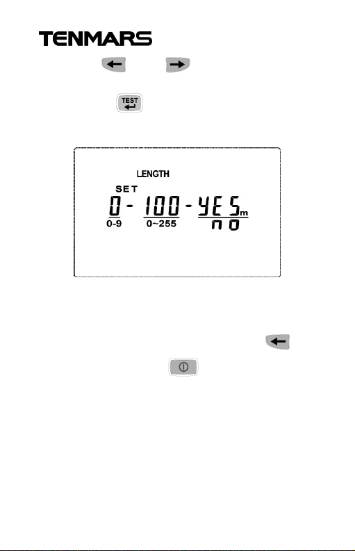
8. Press and key to select known
length measurements value parameter.
9. Press key to enter and exit
setting mode shown in Figure.
14 Checking the LCD and Software
Version
In the shutoff mode, Press and hold
key again press the key to turn on
meter and LCD will keep all dark continued.
16
Page 20
TM-901N/TM-902/TM-903
15 Battery Replacement
Turn off the meter and disconnect all test
leads before replacing the battery.
Use only the correct type of batteries,
properly
installed in the case, to power the meter.
WARNING
If the symbol “ ” appears on the
LCD, please replace the battery
immediately
16 Options and Accessories
Consumers can order options and
accessories as follows:
Remote ID Locator Kit, numbers 2-8.
17 End of life
Caution: this symbol indicates
that equipment and its
accessories shall be subject to
a separate collection and
correct disposal
17
Page 21

TM-901N/TM-902/TM-903
18 Specifications
Cable types tested : UTP, STP
Cable Category tested : CAT5, CAT6
(RJ-11.COAX.TM-903 only).
Test connectors :
Shielded 8-pin modular jack (RJ45),test
voice cable(RJ11)TM-903,and video coax
cable(F-connenector) TM-903.
Wiremap test : Detects opens, shorts,
miswires, split pairs
Length test :
Range : up to 255 m (836 ft)
Resolution : 0.1 m (ft)
Unit : meter and foot
Typical accuracy : ± 10%+1.0m (3 ft)
Display : 58mm(L) x45mm(W)
Monochrome LCD with backlight
Battery : 1.5Vx6 batteries
(LR03 SIZE AAA 1.5V)
Battery Lift : Approx continuous testing
200 times
18
Page 22

TM-901N/TM-902/TM-903
Shutoff Rate Power :1uA
Operate Maximum Power :20mA
Operating temperature and humidity :
5℃to 40℃,below 80% RH.
Storage temperature and humidity :
-10℃ to 60℃, below 70%.
Dimensions : 156(L)*73(W)*35(H) mm.
Weight : About 170g.
Accessories : User’s manual x1, 1.5V
AAA battery x6, CAT5 STP Cable x1,
remote ID(1) x1
19
Page 23

Page 24
Professional Electrical and
Environment Test & Measurement
Instruments:
Battery Capacity / Impedance Tester
LED light meter,Temperature& Humidity meter,
Infrared Thermometer, Sound level meter
Light meter, EMF meter, UV Light meter,
RF meter, Hot wire Anemometer, CO meter
Anemometer, Lan cable tester, CO2meter,
Solar power meter, Radiation meter,
Clamp meter,Multimeter, Phase Rotation test,
Digital Insulation tester
Our products of high quality are selling
well all over the world
TENMARS ELECTRONICS CO., LTD
6F, 586, RUI GUANG ROAD, NEIHU,
TAIPEI 114, TAIWAN.
E-mail: [email protected]
http: //www.tenmars.com
 Loading...