

Page 1
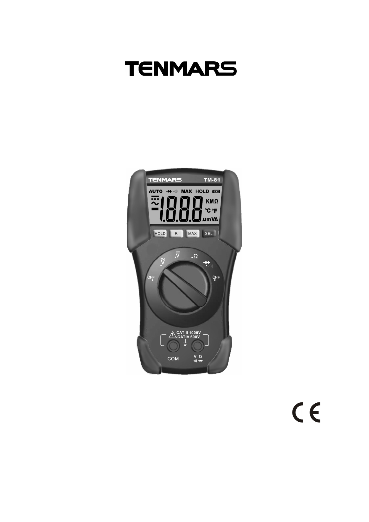
Autoranging Multimeter
TM-81
User’s manual
HB2TM8100000
Page 2

Page 3

TM-81 /TM-82
EN-1
Content:
1. SAFETY PRECAUTIONS AND PROCEDURES.....................................................................2
1.1. Preliminary.............................................................................................................2
1.2. During use.............................................................................................................3
1.3. After use................................................................................................................3
1.4. Measuring (overvoltage) categories definitions .....................................................3
2. GENERAL DESCRIPTION......................................................................................................4
3. PREPARATION FOR USE......................................................................................................4
3.1. Initial......................................................................................................................4
3.2. Supply voltage.......................................................................................................4
3.3. Calibration .............................................................................................................4
3.4. Storage..................................................................................................................4
4. OPERATING INSTRUCTIONS...............................................................................................5
4.1. Instrument description...........................................................................................5
4.1.1. Front panel description .....................................................................................5
4.2. Description of function keys...................................................................................6
4.2.1. HOLD Key.........................................................................................................6
4.2.2. R (RANGE) Key................................................................................................6
4.2.3. MAX Key...........................................................................................................6
4.2.4. SEL Key............................................................................................................6
4.2.5. Backlight key (only TM-82)..........................................................................6
4.2.6. Auto power Off..................................................................................................6
4.3. Measurements.......................................................................................................7
4.3.1. DC Voltage measurement.................................................................................7
4.3.2. AC Voltage measurement.................................................................................8
4.3.3. Resistance measurement.................................................................................9
4.3.4. Continuity test.................................................................................................10
4.3.5. Diode test........................................................................................................11
4.3.6. Temperature measurement (only TM-82).......................................................12
5. MAINTENANCE....................................................................................................................13
5.1. General information.............................................................................................13
5.2. Battery replacement ............................................................................................13
5.3. Cleaning ..............................................................................................................13
5.4. End of life ............................................................................................................13
6. TECHNICAL SPECIFICATIONS...........................................................................................14
6.1. Technical features...............................................................................................14
6.1.1. Safety..............................................................................................................14
6.2. Environment ........................................................................................................15
6.2.1. Environmental conditions................................................................................15
6.2.2. EMC................................................................................................................15
6.3. Accessories.........................................................................................................15
6.3.1. Standard accessories .....................................................................................15
7. SERVICE..............................................................................................................................16
7.1. Warranty conditions.............................................................................................16
7.2. After-sale service.................................................................................................16
Page 4
TM-81 /TM-82
EN-2
AC voltage
DC voltage
1. SAFETY PRECAUTIONS AND PROCEDURES
This meter is compliance with safety Standard EN 61010-1 related to electronic measuring
instruments. For your own safety and to avoid damaging the instrument follow the
procedures described in this instruction manual and read carefully all notes preceded by
this symbol .
When taking measurements:
Avoid doing that in humid or wet places - make sure that humidity is within the limits
indicated in paragraph 6.2.1.
Avoid doing that in rooms where explosive gas, combustible gas, steam or excessive
dust is present.
Keep you insulated from the object under test.
Do not touch exposed metal parts such as test lead ends, sockets, fixing objects,
circuits etc.
Avoid doing that if you notice anomalous conditions such as breakages, deformations,
fractures, leakages of battery liquid, blind display etc.
Be particularly careful when measuring voltages exceeding 20V to avoid risks of
electrical shocks.
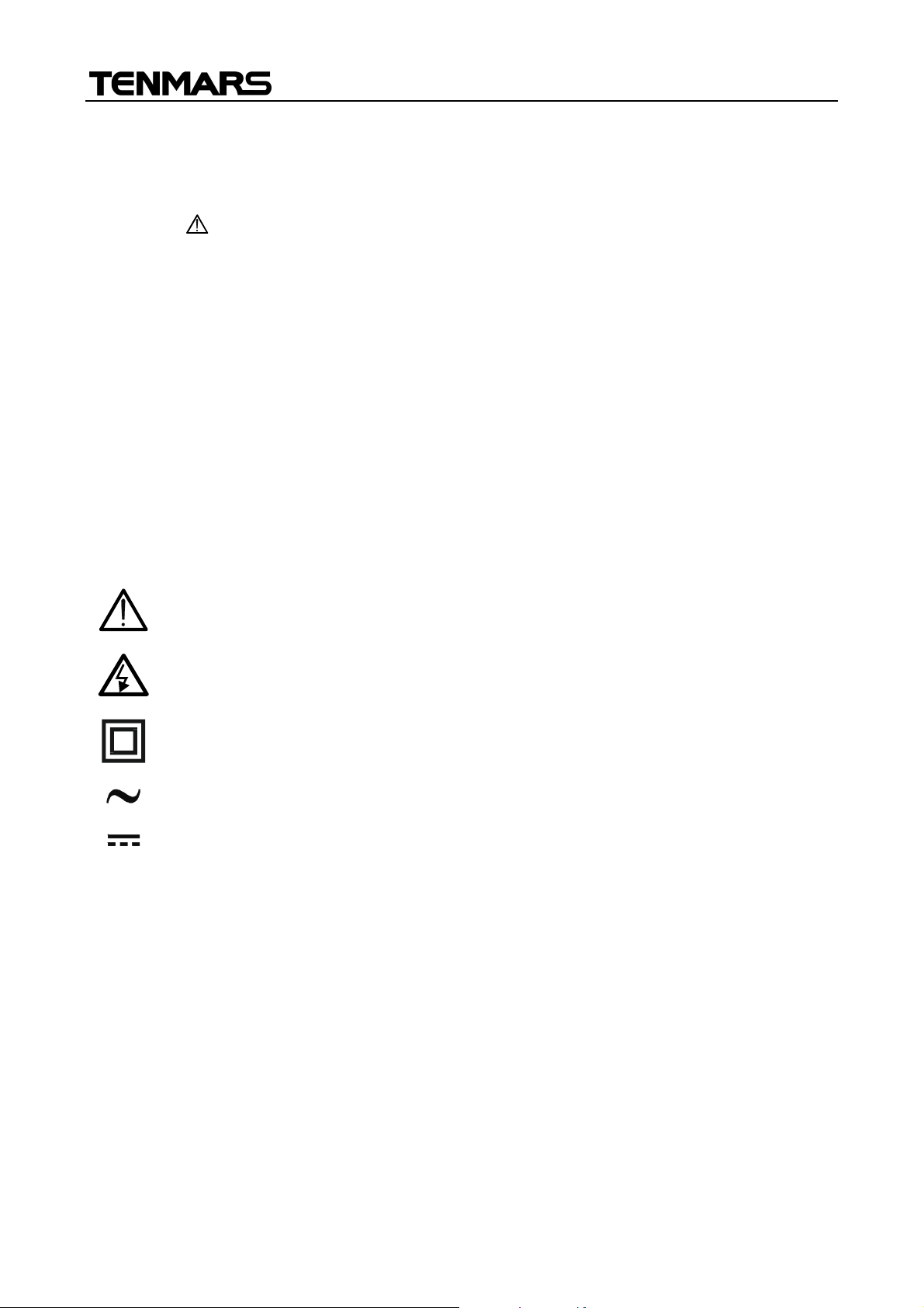
The following symbols are used:
CAUTION - refer to the instruction manual - an improper use may damage the
instrument or its components
Danger high voltage: risk of electric shocks
Double insulated meter
1.1. PRELIMINARY
This instrument has been designed for use in environments of pollution degree 2.
It can be used for VOLTAGE measurements on installations of CAT III 1000V or CAT
IV 600V.
Only the original test leads supplied along with the instrument guarantee compliance
with the safety standards in force. They must be in a good conditions and, if necessary,
replaced with identical ones.
Do not test nor connect to any circuit exceeding the specified overload protection.
Do not take measurements under environmental conditions exceeding the limits
indicated in chapter 6.1.1. and 6.2.1.
Make sure that batteries are correctly installed.
Before connecting the test probes to the installation make sure that the rotary selector
is positioned on the right function.
Make sure that LCD and rotary selector indicate the same function.
Page 5

TM-81 /TM-82
EN-3
CAUTION
1.2. DURING USE
An improper use may damage the instrument and/or its components or injure
the operator.
When changing the range, first disconnect the test leads from the circuit under test in
order to avoid any accident.
When the instrument is connected to measuring circuits never touch any unused
terminal.
When measuring resistors do not add any voltage. Although there is a protection circuit,
excessive voltage could cause malfunctioning.
If during measurement the displayed values remain constant check whether the HOLD
function is active.
1.3. AFTER USE
After using the instrument turn it off.
If you expect not to use the instrument for a long period remove the battery to avoid
leakages of battery liquids which may damage its inner components.
1.4. MEASURING (OVERVOLTAGE) CATEGORIES DEFINITIONS
EN 61010-1: Safety requirements for electrical equipment for measurement, control and
laboratory use, Part 1: General requirements, gives a definition of measuring category,
usually called overvoltage category. Paragraph 6.7.4: Measuring circuits:
(OMISSIS)
circuits are divided into the following measurement categories:
Measurement category IV is for measurements performed at the source of the
low-voltage installation.
Examples are electricity meters and measurements on primary overcurrent
protection devices and ripple control units.
Measurement category III is for measurements performed in the building
installation.
Examples are measurements on distribution boards, circuit breakers, wiring,
including cables, bus-bars, junction boxes, switches, socket-outlets in the fixed
installation, and equipment for industrial use and some other equipment, for
example, stationary motors with permanent connection to fixed installation.
Measurement category II is for measurements performed on circuits directly
connected to the low voltage installation..
Examples are measurements on household appliances, portable tools and similar
equipment..
Measurement category I is for measurements performed on circuits not directly
connected to MAINS.
Examples are measurements on circuits not derived from MAINS, and specially
protected (internal) MAINS-derived circuits. In the latter case, transient stresses are
variable; for that reason, the norm requires that the transient withstand capability of
the equipment is made known to the user.
Page 6

TM-81 /TM-82
EN-4
2. GENERAL DESCRIPTION
This meter performs the herewith measurements:
DC Voltage
AC sine voltage
Resistance
Continuity test
Diode test
Temperature with type K probe (only TM-82)
All selectable by means of a 6-position rotary selector (including OFF position). Also are
available the HOLD key to hold the displayed value, the R key for manual selection of
measure ranges, the MAX key for measure of maximum value and SEL key for selection
between diode test and continuity test and temperature measures in °C or °F (only TM-82).
The selected quantity is displayed with indication of measuring unit and active functions.
The instrument disposes of an Auto Power Off function consisting in an automatic
switching off 15 minutes after last selector rotation.
3. PREPARATION FOR USE
3.1. INITIAL
This instrument was checked both mechanically and electrically prior to shipment. All
possible cares and precautions were taken to let you receive the instrument in perfect
conditions. Notwithstanding we suggest you to check it rapidly (eventual damages may
have occurred during transport – if so please contact the local distributor from whom you
bought the item).
Make sure that all standard accessories mentioned in paragraph 6.3.1 are included.
Should you have to return back the instrument for any reason please follow the
instructions mentioned in paragraph 7.
3.2. SUPPLY VOLTAGE
The instrument is supplied by 2x1.5V batteries type IEC AAA LR03. When batteries are
low, a low battery indication is displayed. To replace/insert batteries please refer to
paragraph 5.2.
3.3. CALIBRATION
The instrument complies with the technical specifications contained in this manual and
such compliance is guaranteed for 1 year. Annual recalibration is recommended.
3.4. STORAGE
After a period of storage in extreme environmental conditions exceeding the limits
mentioned in paragraph 6.2.1 let the instrument resume normal measuring conditions
before using it.
Page 7
EN-5
4. OPERATING INSTRUCTIONS
4.1. INSTRUMENT DESCRIPTION
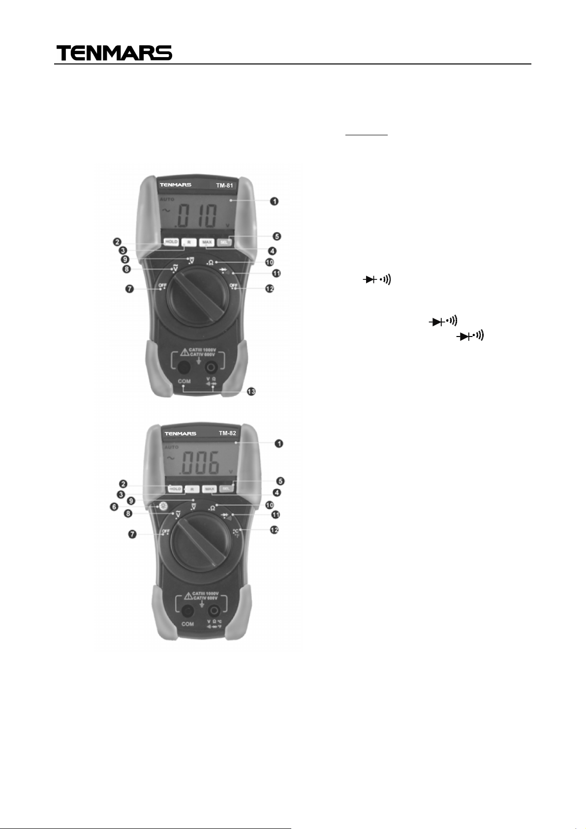
4.1.1. Front panel description
TM-81 /TM-82
LEGEND:
1. LCD
2. Hold Key
3. R Key
4. MAX Key
5. SEL Key
6. Backlight Key(For TM-82)
7. OFF position
8. ACV position
9. DCV position
10. position
11. / position
12. OFF position(for TM-81)
℃/℉ position(for TM-82)
13. COM and V input terminals(for
TM-81) COM and V ℃℉input
terminals(for TM-82)
Fig. 1: Instrument description
Page 8

TM-81 /TM-82
EN-6
4.2. DESCRIPTION OF FUNCTION KEYS
4.2.1. HOLD Key
By pressing HOLD key the measured value is frozen on the display where the symbol
"HOLD" appears. Pressing again HOLD to disable this function and resume normal
operation.
4.2.2. R (RANGE) Key
By pressing R key, the manual mode is activated and the “AUTO” symbol disappears from
the display. Press R cyclically to change the measuring range and fix the decimal point on
the display.
To exit this function keep R key pressed for at least 1 second or rotate the selector to
another position.
4.2.3. MAX Key
By pressing MAX key, maximum value are measured. The symbol corresponding “MAX” is
displayed. This value is stored and automatically updated as soon as an higher value is
measured by meter. Press MAX key again or rotate the selector to another position to exit
from this function.
4.2.4. SEL Key
By pressing SEL key the selection of a double measured functions which are present at
display is possible. In particular this key is active only in / position to select between
diode test and continuity test or in °C°F position (only TM-82) position to select between
°C and °F temperature measure.
4.2.5. Backlight key (only TM-82)
By pressing and hold key for about 3s it’s possible to activate the backlight function on
the display. By pressing and hold key again for about 3s to exit from the function or
waiting the automatically disable after some seconds. The function is available on each
position of the rotary selector.
4.2.6. Auto power Off
The instrument automatically turns off 15 minutes after last pressure of keys or last
selector rotation. To resume operation turn the selector on OFF and turn on the instrument
again.
Page 9
EN-7
4.3. MEASUREMENTS
CAUTION
4.3.1. DC Voltage measurement
The maximum input for DC voltage is 600V. Do not attempt to measure
higher voltages to avoid electrical shocks or damages to the instrument.
TM-81 /TM-82
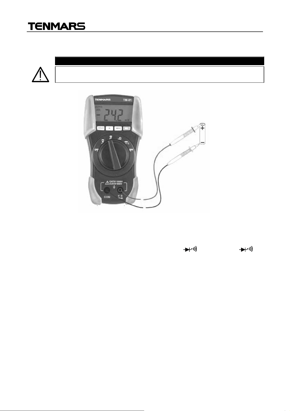
Fig. 2: Using the meter for DC Voltage measurement
1. Pressing the R key to select the correct range or using the Autorange feature (see
paragraph 4.2.2). If the voltage value under test is unknown, select the highest range.
2. Insert the test leads into the jacks, the red plug into V (for TM-81)/ V ℃℉
(for TM-82) jack and black plug into COM jack (see Fig. 2).
3. Connect the red and black test leads to the positive and negative poles of the circuit
under test respectively. The voltage value is displayed.
4. If the message "O.L" is displayed select a higher range.
5. The symbol "-" on the instrument display indicates that voltage has opposite direction
with regard to the connection.
6. For HOLD function and Maximum value measurement please refer to paragraph 4.2.
Page 10
EN-8
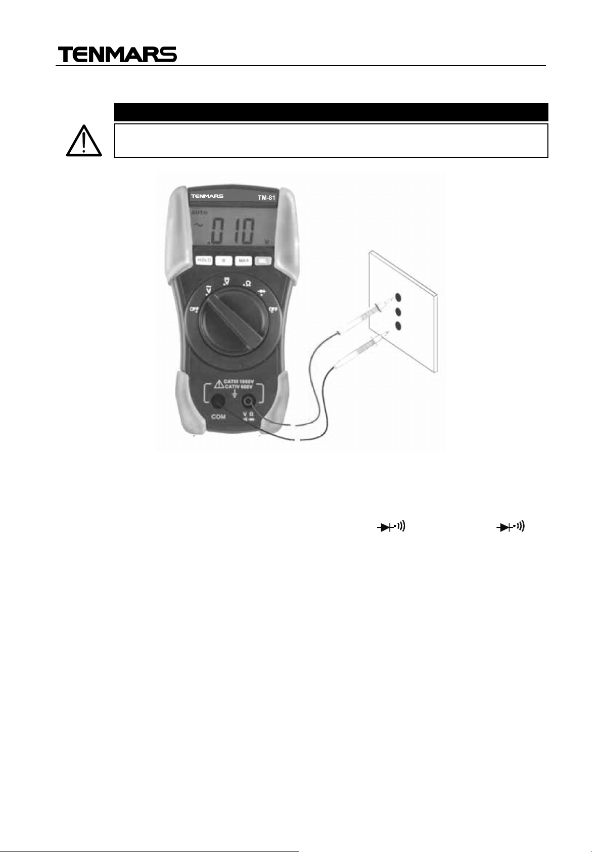
4.3.2. AC Voltage measurement
CAUTION
The maximum input for AC voltage is 600V. Do not attempt to measure
higher voltages to avoid electrical shocks or damages to the instrument.
TM-81 /TM-82
Fig. 3: Using the instrument for AC Voltage measurement
1. Pressing the R key to select the correct range or using the Autorange feature (see
paragraph 4.2.2). If the voltage value under test is unknown, select the highest range.
2. Insert the test leads into the jacks, the red plug into V (For TM-81)/ V ℃℉
(For TM-82) jack and black plug into COM jack.
3. Connect the test leads to the circuit under test; the voltage value is displayed.
4. If the message "O.L" is displayed select a higher range.
5. For HOLD function and Maximum value measurement please refer to paragraph 4.2.
Page 11
EN-9
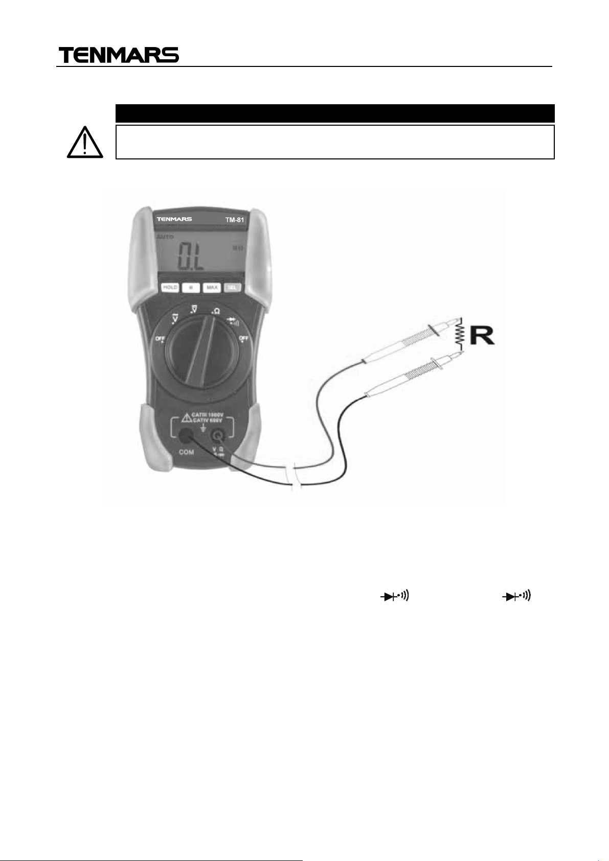
4.3.3. Resistance measurement
CAUTION
Before taking resistance measurements in circuit remove power from the
circuit being tested and discharge all capacitors.
TM-81 /TM-82
Fig. 4: Using the instrument for Resistance measurement
1. Pressing the R key to select the correct range or using the Autorange feature (see
paragraph 4.2.2). If the resistance value under test is unknown, select the highest
range.
2. Insert the test leads into the jack, the red plug into V (For TM-81)/ V ℃℉
(For TM-82) jack and black plug into COM jack.
3. Connect the test leads to the circuit under test; the resistance value is displayed.
4. Indications as ".value
k
" or ".value
M
" (respectively for 2k or 2M) mean
0.valuek and 0.valueM. The zero before comma is not displayed.
5. If the message "O.L" is displayed a higher range must be selected.
6. For HOLD function and Maximum value measurement please refer to paragraph 4.2.
Page 12
EN-10
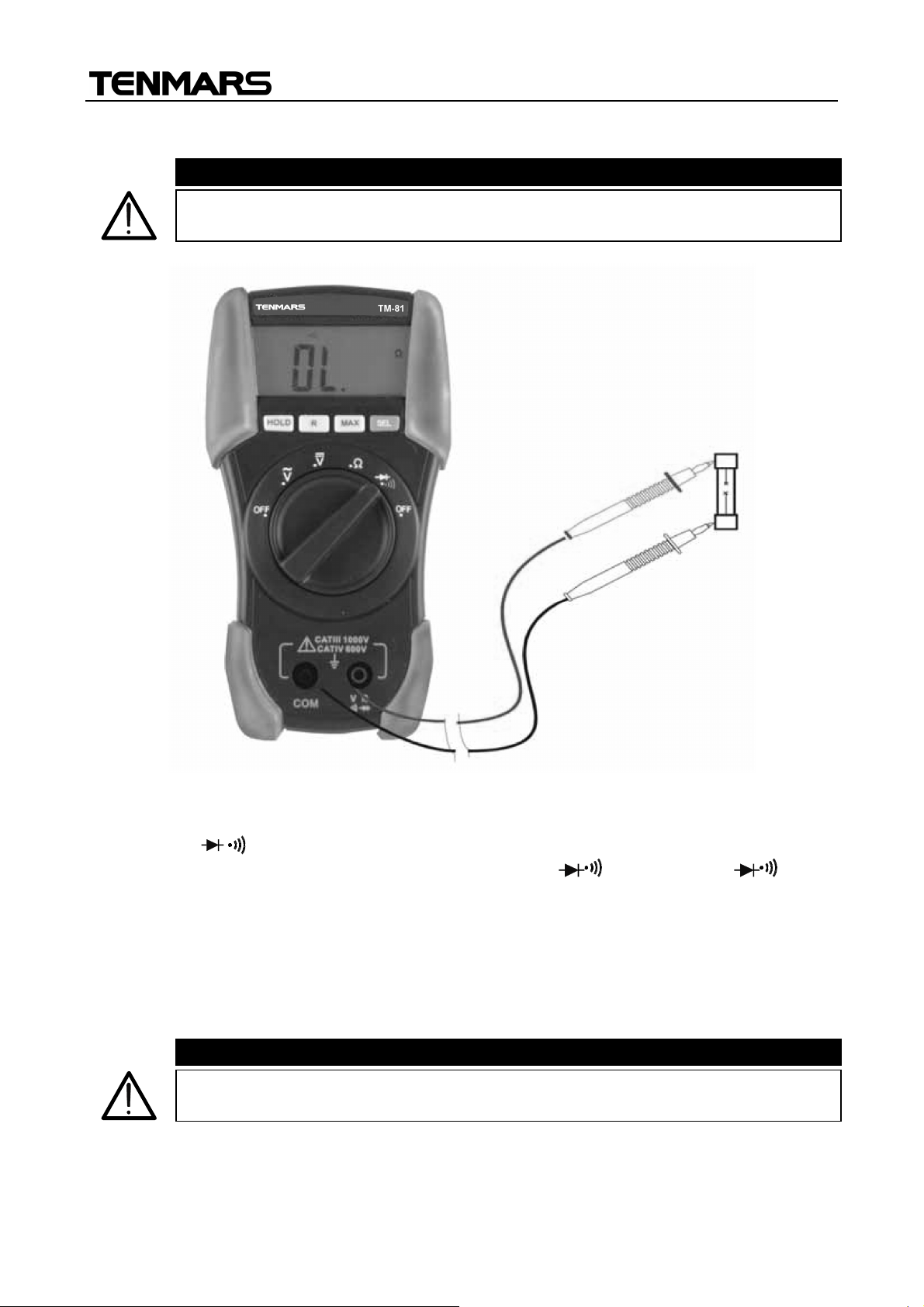
4.3.4. Continuity test
CAUTION
CAUTION
Before taking resistance measurements in circuit remove power from the
circuit being tested and discharge all capacitors.
TM-81 /TM-82
Fig. 5: Using the instrument for continuity test
1. Switch on /
2. Insert the test leads into the jack, the red plug into V (for TM-81)/ V ℃℉(for
TM-82) jack and black plug into COM jack.
3. Connect the test leads to the circuit under test.
4. The resistance value is displayed and the instrument emits a sound signal if the
resistance value is lower than 120.
5. The message "O.L." on the display indicates that the resistance value is higher than
2k.
The displayed value is just indicative and does not correspond to the
resistance value.
then push “SEL” button.
Page 13
EN-11
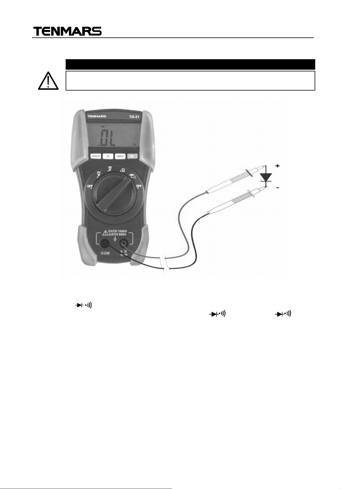
4.3.5. Diode test
CAUTION
Before taking resistance measurements in circuit remove power from the
circuit being tested and discharge all capacitors.
TM-81 /TM-82
Fig. 6: Using the instrument for diode test
1. Switch on /
.
2. Insert the test leads into the jack, the red plug into V (for TM-81)/ V ℃℉(for
TM-82) jack, and black plug into COM jack.
3. Connect the test leads tothe diodeundertest observing the properpolarities.
4. The threshold voltage value expressed in mV under this situation is displayed.
5. If the threshold voltage value is 0V the diode P-N junction is shorted circuit.
6. If the message "O.L" is displayed the diode terminals are reversed, the diode P-N
junction is damaged.
Page 14
EN-12
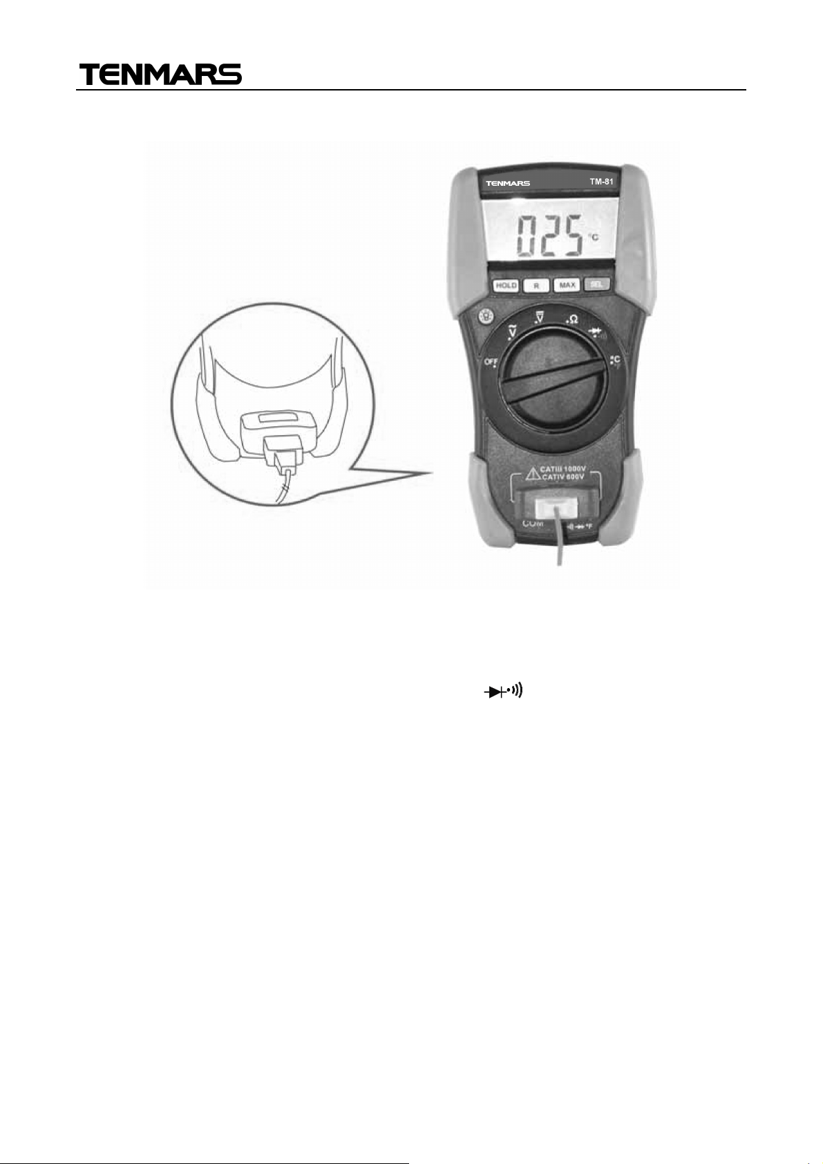
4.3.6. Temperature measurement (only TM-82)
TM-81 /TM-82
Fig. 7: Using the instrument for Temperature measurement
1. Switch on °C°F.
2. Pressing SEL key to select °C or °F measurements.
3. Insert the T10 adapter optional accessory into V ℃℉ jack, and COM jack with
respect of red and black colours (see Fig. 7).
4. Connect the optional K probe (see paragraph 6.3.2.) into the adapter with respect the
correct positive and negative polarity then reading will be displayed.
5. For HOLD function and Maximum value measurement please refer to paragraph 4.2.
Page 15
TM-81 /TM-82
EN-13
CAUTION
5. MAINTENANCE
5.1. GENERAL INFORMATION
This is a precision instrument. To guarantee its performances be sure to use it according to
these instructions and keep it stored on suitable environmental conditions. Do not expose it to
high temperatures or humidity or direct sunlight. Be sure to turn it off after use. If you
expect not to use the instrument for a long period remove batteries to avoid leakages of
battery liquid which could damage the its inner components.
5.2. BATTERY REPLACEMENT
When the low battery indication (refer to paragraph 6.1.7) is displayed the batteries are to
be replaced.
Before replacing the battery disconnect test leads from any energised
circuits to avoid electrical shocks.
1. Turn off the instrument.
2. Disconnect the test leads from the input terminals.
3. Remove the fixing screws from the back case and detach it.
4. Replace the battery with a new one of the same type (refer to paragraph 6.1.7)
observing the proper polarities.
5. Replace the back case and screws.
6. Usetheappropriate batterydisposalmethodsforyour area.
5.3. CLEANING
Tocleanthe instrument use asoftdryclothe. Never use awetcloth,solventsor water.
5.4. END OF LIFE
Caution: this symbol indicates that equipment and its accessories shall be
subject to a separate collection and correct disposal
Page 16
TM-81 /TM-82
EN-14
Range
Resolution
Accuracy
Input Impedance
Overload
protection
2V
0.001V
200V
0.1V
(4
5400Hz)
200mV
0.1mV
not declared
2V
0.001V
200V
0.1V
Loop Voltage
Loop Voltage
1mV
About 1.5Vdc
600Vrms (< 30sec.)
Voltage
6. TECHNICAL SPECIFICATIONS
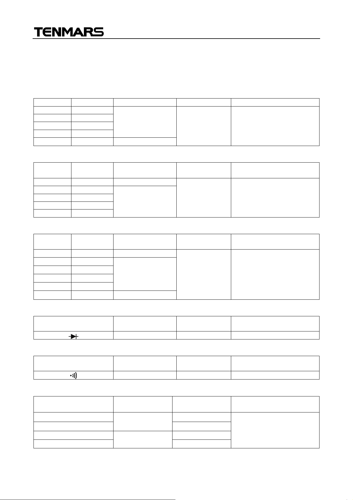
6.1. TECHNICAL FEATURES
The accuracy is indicated as [% of reading + number of digits]. It is referred to the following
environmental conditions: temperature 23°C ± 5°C, relative humidity < 75%.
DC Voltage
200mV 0.1mV
20V 0.01V
600V 1V
(0.8%rdg +1dgt)
(1.0%rdg +2dgt)
AC Voltage
Range Resolution
20V 0.01V
600V 1 V
Accuracy
(1.5%rdg+3dgt)
Resistance
Range Resolution Accuracy
200 0.1 (1.0%rdg + 8dgt)
2k 0.001k
20k 0.01k
200k 0.1k
2M 0.001M
20M 10k (3.0%rdg + 3dgt)
(1.0%rdg + 3dgt)
10M
Input Impedance Overload protection
10M
Max Open
About 3.0V
600VDC/ACrms
600VCC/CArms
Overloadprotection
600VDC/Acrms
(<30sec.)
Diode Test
Range Resolution
Max Open
Continuity Test
Range Beeper
< 120
Max Open Loop
About 1.5Vdc 600Vrms (< 30sec.)
Temperature with K probe (only TM-82)
Range Resolution Accuracy Overloadprotection
-40℃÷1℃
0℃÷ 800℃
-40°F÷ 31°F
32°F÷1382°F
1℃
(2.0%rdg + 3dgt)
1°F
(2.0%rdg + 5dgt)
5°C
9°F
6.1.1. Safety
The instrument complies with: EN 61010-1
Overloadprotection
Overloadprotection
600VDC/Acrms (<30sec.)
Page 17

TM-81 /TM-82
EN-15
(only TM
-
82)
Insulation: Class 2, Double insulation
Pollution degree: 2
Overvoltage category: CAT IV 600V
Max height: 2000m
6.1.7 General data
Mechanical characteristics
Dimensions: 163(L) x 88(W) x 48(H)mm
Weight (including battery): approx. 280g
Power supply
Battery type: 2 batteries 1.5V AAA MN2400 LR03 AM4
Indication of low battery: the symbol " " is displayed when the
battery is low
Battery life: approx. 220 hours
Display
Specifications: 3½ LCD with max. reading 1999 counts +
symbol and decimal point
6.2. ENVIRONMENT
6.2.1. Environmental conditions
Reference temperature: 23° ± 5°C
Working temperature: -5 ÷ 40 °C
Relative humidity: <80%
Storage temperature: -10 ÷ 60 °C
Storage humidity: <70%
6.2.2. EMC
This instrument complies with the requirements of the European Low Voltage Directive
73/23/CEE and Directive CEM 89/336/CEE, revised with 93/68/CEE.
6.3. ACCESSORIES
6.3.1. Standard accessories
Carrying Case
Test leads
Batteries
User’s manual
Adapter for connection type K probe -T10 (only TM-82)
Type K probe for complex or any place hard to enter (-50~200°C/-58~392℉) – TP-03
Accessory Code
Type K probe for liquid or gel temperature (-50~700°C/-58~1292℉)
Type K probe for front or plate temperature (-50~700°C/-58~1292℉)
Type K probe for precise surface temperature ((-50~400°C/-58~752℉))
TP-01
TP-02
TP-04
Page 18

TM-81 /TM-82
EN-16
7. SERVICE
7.1. WARRANTY CONDITIONS
This instrument is guaranteed against material or production defects, in accordance with
our general sales conditions. During the warranty period the manufacturer reserves the
right to decide either to repair or replace the product.
Should you need for any reason to return back the instrument for repair or replacement
take prior agreements with the local distributor from whom you bought it. Do not forget to
enclose a report describing the reasons for returning (detected fault). Use only original
packaging. Any damage occurred in transit due to non original packaging will be charged
anyhow to the customer.
The manufacturer will not be responsible for any damage to persons or things.
The warranty doesn’t apply to:
Accessories and batteries (not covered by warranty).
Repairs made necessary by improper use (including adaptation to particular
applications not foreseen in the instructions manual) or improper combination with
incompatible accessories or equipment.
Repairs made necessary by improper shipping material causing damages in transit.
Repairs made necessary by previous attempts for repair carried out by non skilled or
unauthorized personnel.
Instruments for whatever reason modified by the customer himself without explicit
authorization of our Technical Dept.
The contents of this manual may not be reproduced in any form whatsoever without the
manufacturer’s authorization.
Our products are patented and our logotypes registered. We reserve the right to
modify specifications and prices in view of technological improvements or
developments which might be necessary.
7.2. AFTER-SALE SERVICE
Shouldn’t the instrument work properly, before contacting your distributor make sure that
batteries are correctly installed and working, check the test leads and replace them if
necessary. Make sure that your operating procedure corresponds to the one described in
this manual.
Should you need for any reason to return back the instrument for repair or replacement
take prior agreements with the local distributor from whom you bought it. Do not forget to
enclose a report describing the reasons for returning (detected fault). Use only original
packaging. Any damage occurred in transit due to non original packaging will be charged
anyhow to the customer.
The manufacturer will not be responsible for any damage to persons or things.
Page 19

TM-81 /TM-82
TENMARS ELECTRONICS CO., LTD
6F, 586, RUI GUANG ROAD, NEIHU,
TAIPEI 114, TAIWAN.
E-mail: [email protected]
http://www.tenmars.com
 Loading...