

Page 1
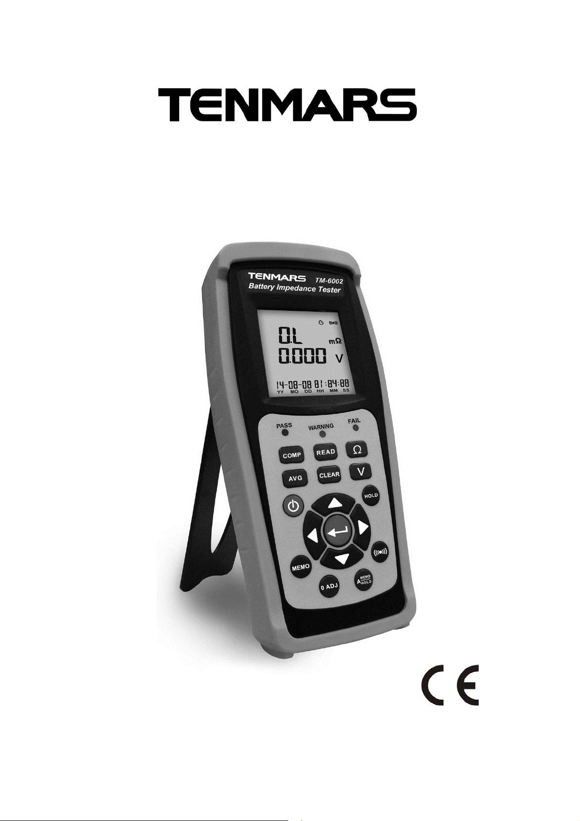
TM-6002
Battery Impedance Tester
User’s Manual
HB2TM6002001
Page 2

CONTENTS
1. Features .................................................................................................... 1
2. Accessories .............................................................................................. 1
3. Safety Precaution ..................................................................................... 2
4. Meter Description ...................................................................................... 3
5. General specifications .............................................................................. 5
6. Electrical specifications: ............................................................................ 6
7. Operation: ................................................................................................. 8
8.1 Enable average function ............................................................. 9
8.2 Clock setup ................................................................................. 9
8.3 Comparator Settings ................................................................. 10
8.4 DC Current (DCA) measurement .............................................. 11
8.5 . DATA HOLD and Back light function ....................................... 11
8.6 Auto Hold and Auto Recording function .................................... 11
8.7 Manual data logging mode and Clear data logger memory ...... 12
8.8 Auto power off setup ................................................................. 12
5. Battery Replacement .............................................................................. 13
6. External DC Power ................................................................................. 13
7. Software installation ................................................................................ 14
8. End of Life Disposal ................................................................................ 17
Page 3

1. Features
1. The Battery Tester is designed for measuring the internal impedance
and open circuit voltage of the secondary battery including Nickel-metal
hydride battery ( NiMH),Nickel-cadmium battery(NiCd),Lithium-ion
battery(Li-ion), Alkaline battery and lead-Acid battery.
2. AC four-terminal method to measure the internal impedance by
eliminating lead impedance and contact impedance to get the accurate
results.
3. Multi-display to show the internal impedance, voltage and clock of the
battery simultaneously.
4. It has 99 sets of composite comparator function, which can be set at
impedance and voltage values to get the reliable detection of battery
deterioration.
5. Pin type leads, which can easily contact the battery electrodes supplied
as standard to get more accurate 4-terminal measurement.
2. Accessories
.
1 Meter
1 User’s Manual
1 Kevin Clip type leads with temperature sensor
1 Pin type leads
1 AC100~240V 9V/1A(5.5*2.1*1.0mm) switching transformer
6 1.5 V – LR6 – AA – AM3 – MN 1500.
1 Carrying Case
1 5-pin USB cable
1 Installation CD
Page 4
TM-6002
3. Safety Precaution
CAUTION
Take extreme care for the following conditions while
measuring.
1. Measuring voltage over 20V as it may cause human body electricity
conduction.
2. Do not measure voltage, current under humid or wet environment. If any
unusual condition of test leads’ send
3. (Metal part). And attachment of the meter, such as breakage, deformation,
fracture, foreign substance, No display, etc., do not conduct any measuring.
4. Do not contact any exposed metal (conductive) parts, such as end of test
lead, jack, fixing object, circuit etc,.
5. Keep you insulated from the object waiting for measuring.
6. Do not operate the meter under the environment with explosive gas
7. (material), combustible gas (material) steam or filled with dust.
8. In order to avoid reading incorrect data, you have to replace the batteries
immediately when the symbol BAT appears on the LCD.
9. In order to avoid the damage caused by contamination and static electricity,
do not touch the circuit board before you take any adequate action.
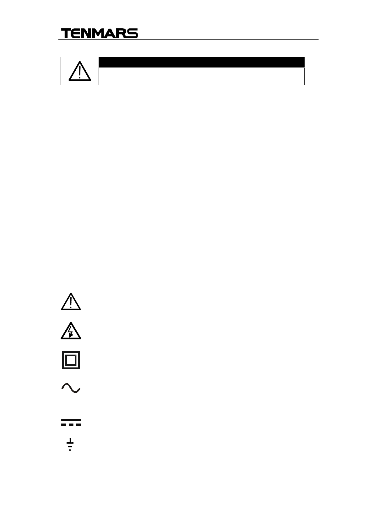
Symbols Description
Caution
Danger high Voltage:risk of electric shock
Meter Double insulated
AC Voltage or Current
AC Voltage or Current
Ground
:
2
Page 5
TM-6002
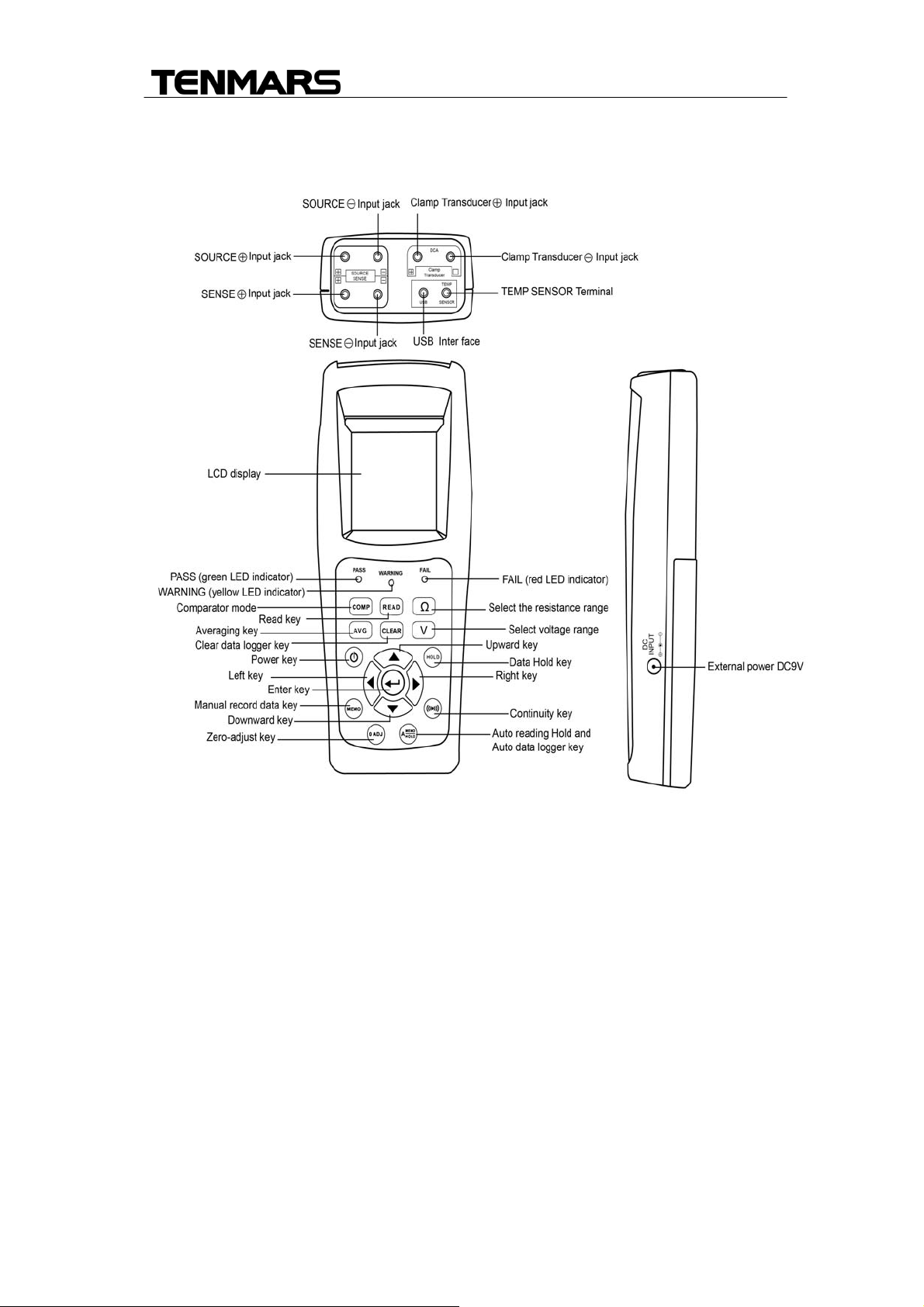
4. Meter Description
FIG (1)
3
Page 6
TM-6002
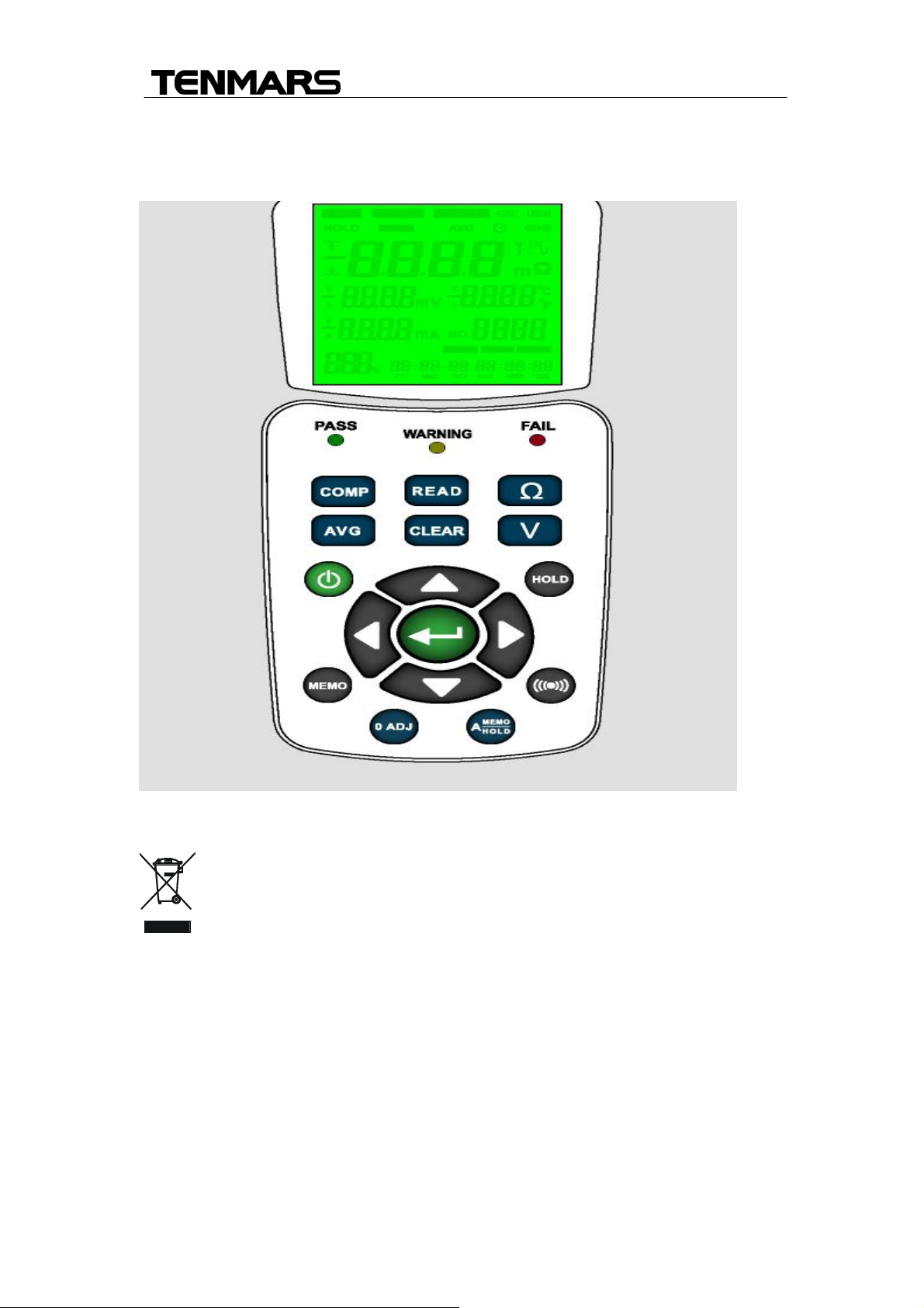
1. LCD display.
2. PASS LED :To indicate the tested battery complies with the high limit of
comparator.
3. WARNING LED:To indicate the tested battery is going to deteriorate.
4. FAIL LED:To indicate the tested battery has deteriorated.
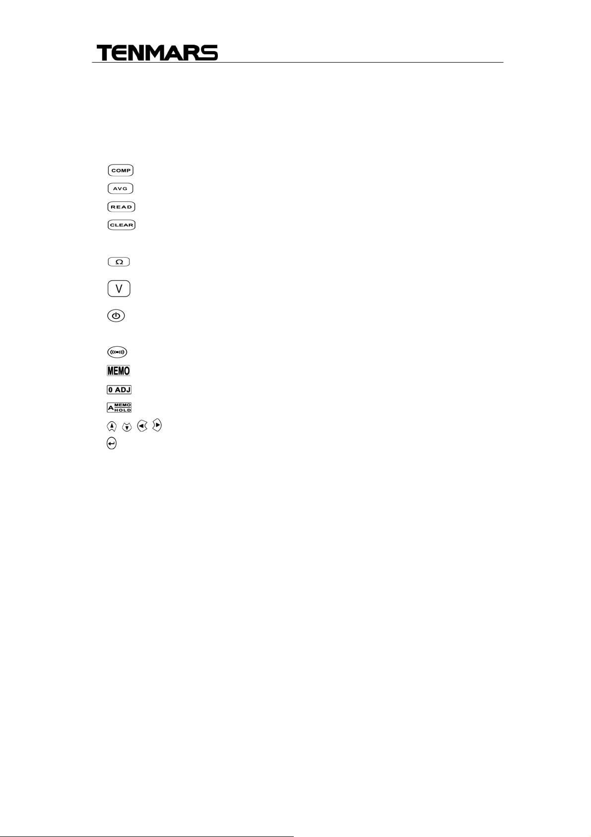
5. key :Comparator function.
6. key :Average function.
7. key :To show the data logged readings.
8. key :To delete single data logged reading in the memory and
settings date/time.
9.
10.
key :Select the impedance range. (40mΩ, 400mΩ, 4Ω, 40Ω)
key :Select the voltage range. (4V, 40V)
11. key :Power ON/OFF.
12. HOLD key :Hold or disable -hold function for the displayed values.
13. key :Turn the beeper on or off
14. key :For recording the displayed values.
15. key :For implementing the zero-adjust feature.
16. key :Select the auto-hold and auto-memory feature.
17. key :For configuration settings and changing their values.
18. key :To set the configuration with entering values.
19. SOURCE+ input jack:For connecting with the red test lead plug.
20. SOURCE- input jack:For connecting with the back test lead plug.
21. SENSE+ input jack:For connecting with the yellow test lead plug.
22. SENSE- input jack:For connecting with the blue test lead plug.
23. TEMPSENSOR input jack:For connecting the plug of the temperature
sensor.
24. DCA+ input jack:For connecting with the red test lead plug to current
probe.
25. DCA- input jack:For connecting with the back test lead plug to current
probe.
26. USB interface:Used for connecting the USB cable.
27. DC input jack:Used for connecting the external power DC 9V input.
4
Page 7

TM-6002
5. General specifications
Measuring method:Impedance (AC four-terminal method).
A/D conversion: Dual slope method.
Display:LCD display and LEDs (comparator output).
Sampling rate:2 Second.
Open-Circuit terminal voltage: 7.0Vp-p max.
Input over range: the screen displays“OL”.
Low battery detection: the screen displays “ ”.
Auto power off: The meter will turn off automatically after about 15 minutes of
inactivity, allows user to set the inactive time (01~99 minutes).
Comparator settings: High and Low limits of the comparators impedance and
voltage.
Number of comparator settings: 99 sets.
Manual and auto continuous Data logging: 9999 sets.
Operating temperature and R.H. value: 5°C to 40°C, 80%RH or less (non-
condensation).
Storage temperature and R.H. value: -10°C to 60°C, 70%RH or less
(non-condensation).
Operating ambience: In-door use, under environmental pollution grades two.
Operating attitude: Max 2000 meters above level.
Power supply: 1.5V × 6 NEDA 15F IEC R6 JIS SUM-3(ALKALINE).
AC adapter:AC input Voltage is 100Vac to 240Vac 1.0A with input frequency
of 60 HZ or 50HZ,Free Voltage DC output is 9VDC(8~12VDCMax) Supply
current:>1.0ADC. Socket:pin Ground Casing Positive External Diameter
5.5mm internal Diameter 2.1mm.
Dimension and weight: 240mm(L) x 100mm (W) x 45mm(H). approximate
700g(including batteries).
Fuse specification: 0.5A/250V, 3.6Øx 10mm.
5
Page 8
TM-6002
6. Electrical specifications:
To ensure accuracy the ambient temperature should be 23°C ± 5°C with
a humidity of 80% RH (maximum) non-condensing. In addition, perform
a Zero adjustment after each range change.
Resistance measurements
Temperature coefficient :±(0.1% rdg +0.5digits)/℃.
Measurement current frequency:1KHZ±30HZ.
Measurement open-circuit terminal voltage:7Vp-p
CAUTION
The maximum input for DC voltage is 40V (No AC voltage
Input permitted). Do not attempt to measure high voltages to
avoid electrical shocks or damages to the instrument.。
Range Resolution Measurement current Accuracy
40mΩ
400 mΩ
4Ω
40Ω
10μΩ
100μΩ
1mΩ
10mΩ
100mA approx.
15mA approx.
1.5mA approx.
150μA approx.
±(0.8% reading +
10digits)
Voltage Measurements
Temperature coefficient :(±0.1% rdg ±0.5digits)/℃
CAUTION
The maximum input for DC voltage is 40V(No AC voltage
Input permitted). Do not attempt to measure high voltages to
avoid electrical shocks or damages to the instrument.。
Range Resolution Accuracy
4V
40V
Temperature measurement
Measurement Range Resolution Accuracy
-20℃~60℃
-4℉~140℉
1mV
10mV
0.1℃
0.1℉
±(0.1% reading +6digits)
±1.0℃
±1.8℉
6
Page 9

TM-6002
DC Current (DCA) measurement
CAUTION
The maximum input for DC current is 700A. Do not
attempt to measure higher currents to avoid electrical
shocks or damages to the instrument.
Range Sensitivity Resolution Accuracy
700A
0.6A~700.0A
0.1A
±(2.0% reading +5digits)
7
Page 10
TM-6002
7. Operation:
CAUTION
Do not attempt to measure DC voltage exceeding
40V。Do not attempt to measure AC voltages, This
could result in jury or damage to the unit
Do not attempt to measure the voltage of a generator.
This would result in an AC voltage being applied to the
voltage generating output terminals, which is
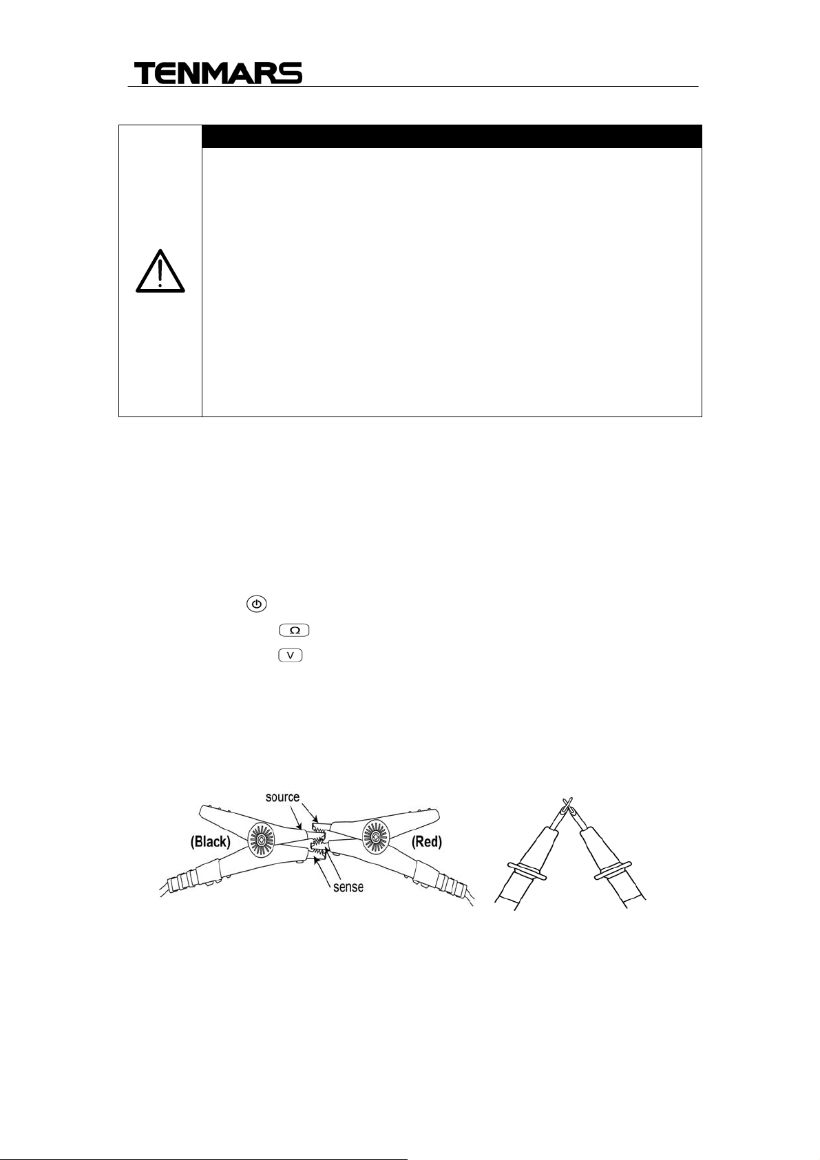
1. Connect the following test leads to the meter:
dangerous.
After measuring a high voltage battery, before
continuing to measure a low voltage battery first short
the measurement leads together. This will discharge
the DC-elimination capacitor which is connected
across the leads. Otherwise an excess voltage may be
applied to the low voltage battery, which is dangerous.
Red test lead to SOURCE〝+〞jack
Black test lead to SOURCE〝-〞jack.
Yellow test lead to SENSE〝+〞jack
Blue test lead to SENSE〝-〞jack.
Temperature plug to TEMP SENSOR .
2. Press power key turn on the meter。
3. Press Ω-RANGE key to select desired impedance ranges。
4. Press V-RANGE key to select desired voltage ranges。
5. The zero adjustment function is to zero range of impedance. The reading
during zero adjustment will be taken as zero and will be used to calibrate
subsequent measurements.
6. (1).Short the red and black test leads probe four (4) terminals.
8
Page 11
TM-6002
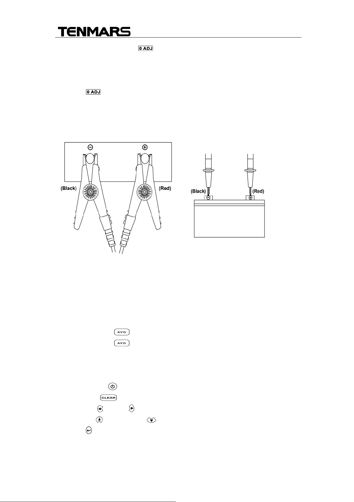
7. Press Zero adjustment key for 2 seconds to start the zero
adjustment. A flashing “0 ADJ” appears on the screen; when the tester
reads a steady value of the resistance lower than 1000; then the screen
displays “0” and stop flashing ”0 ADJ”.
Press key again to disable the zero adjustment.
8. Connect the red test probe to the positive battery terminal, and the black
test probe to the negative battery terminal.
9. Read the battery internal impedance or DC voltage directly and
Temperature measurement from the display.
Note:When the measured DC voltage or battery internal impedance value is
over range, “OL”is displayed.
8.1 Enable average function
1. Press average key to enable the average function.
2. Press average key again to exit average function.
8.2 Clock setup
The clock of this meter is 24-hour time format.
1. Press power: key to turn on the meter,
2. Press clear key to enter the clock setting mode.
3. Press left or right key to select the options for adjustment.
4. Press up key or down key to change the digit.
5. Press key to store the setup and exit the mode.
9
Page 12

TM-6002
8.3 Comparator Settings
The comparator function compares the measured values with preset High and
Low limit values for internal impedance and voltage level, and determines the
range that the measurement should fall into. Then according to the following
conditions to light the corresponding LED, and sounds a beeper under the
WARNING and FAIL cases.
1. Press power:
2. Press comp
key turn on the meter.
key for 2 seconds the display will show ”COMP” and
No ” 00” .Each flashing to enter the comparator setting mode.
3. Use the up key or down key to select the desired comparator
number form 01 up to 99.
4. Press left or right key to select option to adjust comparator low limit
resistance and low limit voltage mode or select option to adjust comparator
high limit resistance mode or select option to adjust comparator voltage
and current mode.
5. If select option to adjust comparator high limit resistance mode, Press
comp key to display will blink ”COMP” to enter comparator setting if
high limit resistance.
6. Press Ω-RANGE key to select high limit resistance range.
7. Press left or right key to select option to adjust comparator high limit
resistance
8. Press up key or down key to change the digit.
9. If you select option to adjust comparator low limit resistance and low limit
voltage mode of step 5.
10. Press comp
key to display will blink ”COMP” to enter comparator
setting if low limit resistance and low limit voltage mode.
11. Press Ω-RANGE key to select low limit resistance range. or Press
V-RANGE key to select low limit voltage range.
12. Press left or right key to select option to adjust comparator low limit
resistance and voltage
13. Press up
key or down key to change the digit.
14. If you select option to adjust comparator voltage and current mode of step
5.
15. Press comp key to enter comparator setting voltage and current
mode
16. Press V-RANGE key to select low limit voltage range
17. Press left or right key to select option to adjust comparator voltage
and current.
10
Page 13
TM-6002
18. Press up key or down key to change the digit.
19. Press key to store the setup, exit the mode
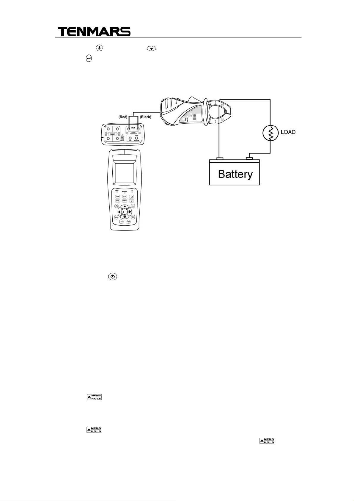
8.4 DC Current (DCA) measurement
1. Connect the current probe to meter:
+ red signal output to DCA+ JACK, and - black to signal output to DCA-
JACK
2. Press power: key turn on the meter.
3. Open the clamp and put the tested conductor in the center or clamp jaws.
4. The current value. Will be indicated on the LCD.
8.5 . DATA HOLD and Back light function
1. Press HOLD key to enable data hold function.
2. Press HOLD key again to disable data hold function.
3. Please press HOLD key for more than 2 seconds to turn on the backlight
display
8.6 Auto Hold and Auto Recording function
1. Press " " key to start the auto-hold function, the symbol of “A.HOLD”
and “HOLD” appear on the screen.
2. Press “HOLD” key to disable the hold function.
3. Press “ “ key for three times, the symbol of ”A.HOLD “ and
“A.MEMO“ appear to start the Auto-recording function. Press “ “ key
again to disable the Auto-recording function.
11
Page 14

TM-6002
8.7 Manual data logging mode and Clear data logger memory
1. Press manual data logging key enable manual data logging mode
the display will show increase memory number.
2. Press reading key to view logged readings mode
3. Press up key or down key to scroll through the readings, The LCD
display will show READ. No:xxxx indicating memory number and measure
value for internal resistance and voltage、 time、 temperature、 DC current.
4. Press clear key to delete sing data logged reading in the memory.
8.8 Auto power off setup
1. Press power: key turn on the meter, Press power: key again for 2
seconds to disable auto power off function.
2. Press power: key again for 2 seconds to auto power off setting mode.
3. Press up key or down key change the auto power off time. The
auto power off time default value is 15 minutes.
4. Press enter key store the setup, exit the mode.
12
Page 15
TM-6002
5. Battery Replacement
WARNING
If the symbol “ ” appears on the LCD, please replace the
battery immediately
The meter is powered by 1.5V battery x6pcs (NEDA 15F IEC R6 JIS UM-3).
For the battery replacement procedure, please follow the steps below:
Press power off key to turn the instrument off.
Use a screw driver to unfasten the screws on the battery cover and remove
the cover
Take out the old batteries and replace with new batteries, taking care to
note the correct polarity.
Re-install the battery cover and tighten the holding screws.
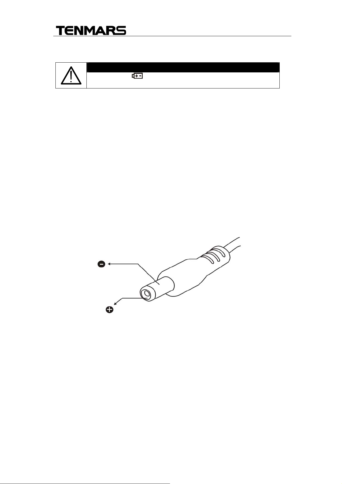
6. External DC Power
External AC to DC adapter: Voltage 9VDC(8~12VDCMax)
Supply current:>1.0ADC
Socket:pin Positive, Ground Casing External
Diameter 5.5mm; internal Diameter 2.1 mm
13
Page 16
TM-6002
7. Software installation
PC requirement:
․CPU:PentiumⅢ 1000MHZ.
․RAM:SDRAM 512MB.
․Hard Disk:200MB.
․OS:Windows XP、Windows 7、Windows 8.
․Display:1024×768 256 color.
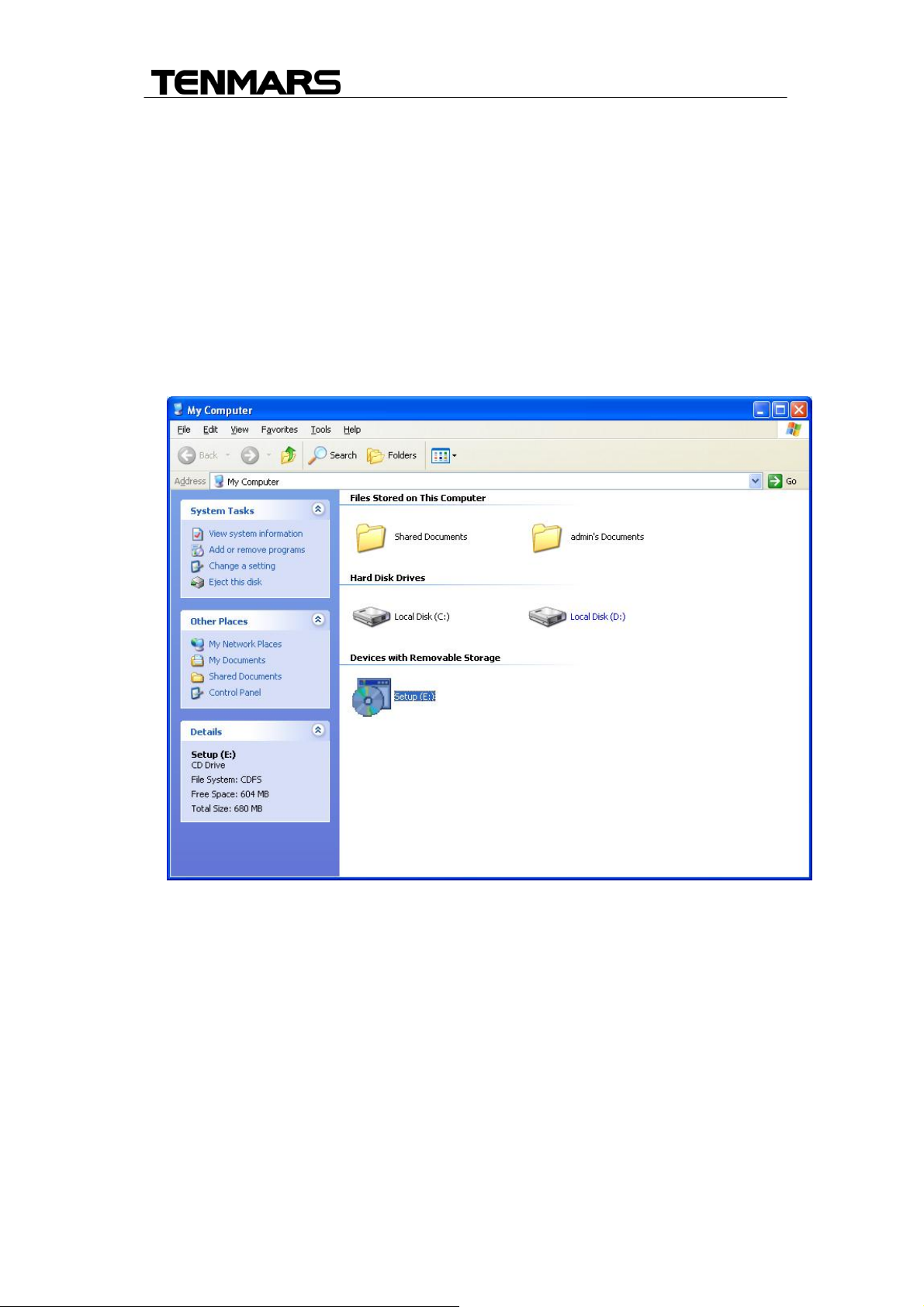
1. Insert the CD into the PC to install the software
first.
14
Page 17
TM-6002
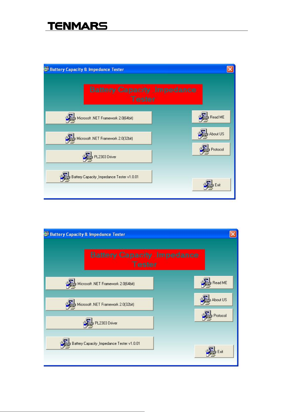
2. Select the USB drive to be installed, which is PL-2303 Drive Installer.exe,
click twice on the left key of the mouse to install the USB driver.
3. Select the Microsft.NET Framework2.0(32bit) or (64bit) installs the
desktop icon.
15
Page 18
TM-6002
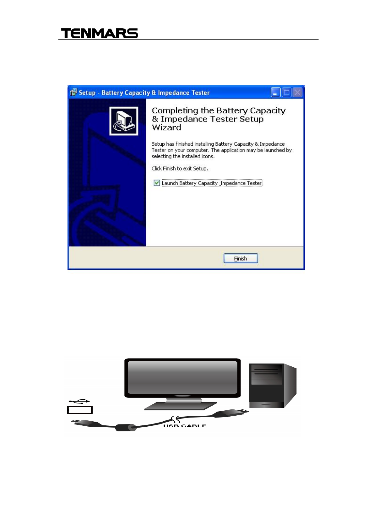
4. Select the Battery Capacity Impedance Tester V1.0.01and installs the
desktop icon
5. Remove the CD from PC after completed the installation.
6. Use the USB cable to connect the meter and computer according to the
drawing.
16
Page 19
TM-6002
7. Select the desktop icon and click twice on left key of the mouse to run the
procedure.
8. End of Life Disposal
Caution: this symbol indicates that equipment and its accessories
shall be subject to a separate collection and correct disposal
17
Page 20

TENMARS ELECTRONICS CO., LTD
6F, 586, RUI GUANG ROAD, NEIHU,
TAIPEI 114, TAIWAN.
E-mail: [email protected]
http://www.tenmars.com
 Loading...