

Page 1
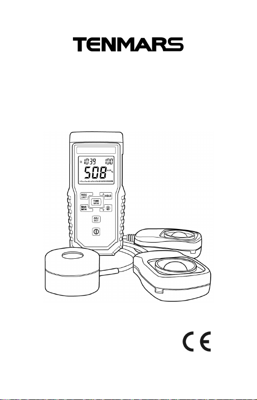
Illumination -Solar -UVA
3 in 1 Light Meters
TM-208A
User’s Manual
HB2TM208A002
Page 2

Page 3

Content:
1. Introduction................................................1
2. Accessories................................................1
3. Specifications.............................................2
3.1. General Specifications ..............................2
3.2. UVAElectrical Specification......................3
3.3. Solar Power Electrical Specification.........4
3.4. Illumination Electrical Specification.........5
4. Safety Precaution:......................................6
5. Illumination Instruction..............................6
6. Instrument description..............................9
7. LCD description.......................................10
8. Operation.................................................. 11
9. Software installation................................22
10. Maintenance or Repair.............................25
11. PRECAUTIONS.........................................25
12. Battery Replacement ...............................26
13. Product Disposal:....................................26
Page 4

TM-208A
1. Introduction
Illumination -Solar -UVA3 in 1 Light Meters
UV-Ameter applications include:
The complete source for all your UV curing
needs.
UV Curing.
Fly trap.
UV-A Lamp Monitoring.
Illumination meter can be used in all indoor or
outdoor visible lighting measurements.
Solar power meter applications include:
Estimating PV array power output.
Monitoring solar PV panel input.
Measuring outdoor solar irradiance.
2. Accessories
1
Meter
1
User’s Manual
3
Illumination and Solar and UVA
sensor each one.
1
9V battery
1
Carrying case
1
USB cable and Installation disk
1
AC to DC adaptor
1
Page 5

TM-208A
3. Specifications
3.1. General Specifications
Battery life: approx. 100 hr.
Display: 3 3/4 LCD display with back light
maximum display 4000.
Sampling: 4 times/second.
Auto power off and disable auto power off.
Enable and disable auto power offfunction
(default 30 minutes).
Low battery indication“ ”.
Over load display “OL”.
Maximum/Minimum/Average record and elapse
time.
Auto zero adjustment.
Data Output: USB PC serial interface.
Datalogging capacity up to 45,000 reading.
Power: 9V battery、 NEDA1604、IEC6F22 or JIS
006P.
Size: 130(L) x 56(W) x 38 (H)mm.
Weight: approx.250g.
Consumption Current: ≦10mA.
Sensor length:1.0M.
AC to DC Adaptor
External AC 100~240V to DC 9V/0.5A power
supply
2
Page 6
TM-208A
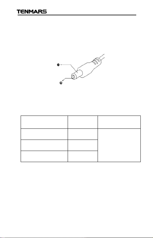
Plug: The pin in the center connects to the
positive electrode and the outer case is negative
electrode
Diameter: 5.5mm; internal diameter: 2.1mm
3.2. UVA Electrical Specification
Accuracy is indicated as [% FS + digital]. Environmental
conditions at 23°C ± 5°C with RH < 80%.
Measuring range Resolution Accuracy (25°C)
400.0 μw/cm
4000 μw/cm
20 .00 mw/cm
2
2
0.01 ± 4(%FS + 2dgt)
1
2
0.01
/< ±3/year
FS: full scale
Wavelength: 320 - 390 nm.
Peak sensitivity wavelength: 365 nm.
Sensor: The exclusive photo diode & UVAcolor
correction filter
3
Page 7
TM-208A
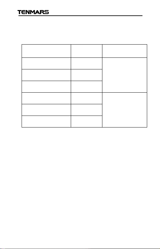
3.3. Solar Power Electrical Specification
Accuracy is indicated as [ % reading + digital] Environmental
conditions at 23°C ± 5°C with RH < 80%.
Measuring range Resolution Accuracy (25°C)
40.00 W/m
400.0 W/m
2000 W/m
13.00 BTU /(ft²*h) 0.01 3 BTU /(ft²*h) or
127.0 BTU /(ft²*h) 0.1
634 BTU /(ft²*h) 1
2
2
2
0.01 ± 10W/m² or
0.1
1
±5%
±5%
whichever is greater in sunlight;Additional
temperature induced error ±0.38W/m² / °C
[ ±0.12 BTU / (ft²*h)/ °C] from 25°C
Peak sensitivity wavelength: 400 - 1100 nm.
4
Page 8
TM-208A
6% other visible light source
Angle deviation
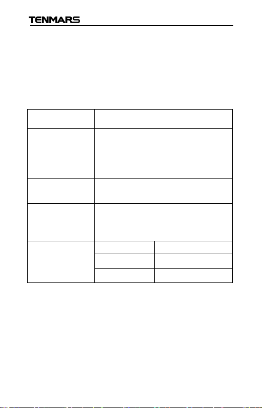
3.4. Illumination Electrical Specification
Accuracy is indicated as [% reading + digital]
Environmental conditions at 23°C ± 5°C with RH <
80%
Sensor Silicon photodiode and filter
Measuring
Range
Resolution 0.01, 0.1, 1, 10, 100 Lux
Accuracy ±3% (Calibrated to standard
from cosine
characteristics
Peak sensitivity wavelength:380 - 780 nm.
Cosine angular corrected.
According to JIS C 1609:1993 and CNS 5119
general A class Specifications.
Peak sensitivity wavelength:550nm
40.00,400.0 ,4000,
40000,400000 Lux
40,400,4000,40000
Foot-candles
0.01, 0.1, 1, 10 Foot-candles
incandescent lamp 2856∘K)
°
30
60
80
°
°
±2%
±6%
±25%
5
Page 9

TM-208A
4. Safety Precaution:
Caution! Please refer to this manual.
Improper use may damage the meter and its
components.
Complies with European Directive.
Do not operate in environments with flammable gas or humid
environments.
Operating altitude: up to 2000M.
Operating environment: Indoor use; Pollution degree 2.
Clean with soft cloth when dirty, such as glasses cloth. Do not
clean with chemicals and other solvents.
EMC: EN61326-1: CISPR 11: Group 1, Class B
Class B – Equipment for use in all establishments other than
domestic.
Group 1 – RF energy generated is needed for internal
functioning.
5. Illumination Instruction
The flux of light received in a unit area of a certain
side being shone is popularly known as illumination.
In both United Kingdom and United States, the unit is
known as foot-candle light, but in Europe it is known
as meter candlelight.
The unit is defined as the amount of illumination the
inside surface an imaginary 1-foot radius sphere
would be receiving if there were a uniform point
source of one candela in the exact center of the
sphere. Alternatively,it can be defined as the
illumination on a 1-square foot surface of whichthere
is a uniformly distributed flux of one lumen.This can
be thought of as the amount of light that actually falls
6
Page 10
TM-208A
on a given surface. The foot-candle is equal to one
lumen per square foot. Its abbreviated form is written
as 1 Fc=1 Lm/ft, similarly, one-meter candlelight is
the illumination of lightthat falls ona side thatlies in a
distance one meter away from a one-meter
candlelight and exactly intersects the light. It isalso
called Lux i.e. the flux of light being received in each
sq. meter is called the illumination of one lumen.
As 1 candle=10.764 Lux.
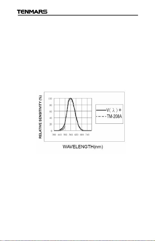
Relative Spectral (SENSITIVITY)
NOTE 1.:When the light sensor cap is not attached
on the sensor, the word “CAP”will appear onthe LCD.
Make sure that the cap is attached on the sensor. If
the zero adjustment has not been made correctly,
some digits will still appear on the LCD instead of
0.00. In this case, please make the zero adjustment
again.
7
Page 11

TM-208A
NOTE 2.:Light Source Luminous Intensity (cd)
calculated if a single light source is used and is
regarded as a single-point light source, the luminous
intensity of the light source can be calculated and
displayed, by setting the distance from the light
source to the measuring point.
Luminous intensity (cd) = illuminance (Lux) x distance
2
(m)
Set the distance to the measuring light source in
advance.
8
Page 12
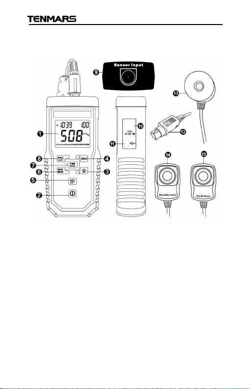
6. Instrument description
TM-208A
1. LCD
2. Power Button
3. Backlight/Down
Button
4. Hold/Up Button
5. ADJ/SET Button
6. MAX/AVG/Min
Button
7. Time/MEM button
8. Recode/ UNIT
switch Button
9. Sensor connecting
jack
10. External power DC 9V
11. USB interface
12. Sensor connecting
plug
13. UVA Sensor
14. Illumination sensor
15. SOLAR Sensor
9
Page 13
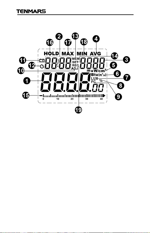
7. LCD description
TM-208A
1. Numeral reading
value
2. Time unit (hour:
minute: month:
second)
3. Memory reading
symbol
4. AVG. symbol
5. W/m2/mw/cm2/
uw/cm2unit.
6. Btu (ft2*h) unit.
7. Lux unit.
8. % unit
9. FC unit.
10. Adj symbol.
11. Low battery symbol.
12. Auto power off
symbol.
13. MEM symbol.
14. Set symbol.
15. Analogue bar graph
16. Hold symbol
17. Max symbol
18. Min symbol
19. REC symbol
10
Page 14
TM-208A
11
8. Operation
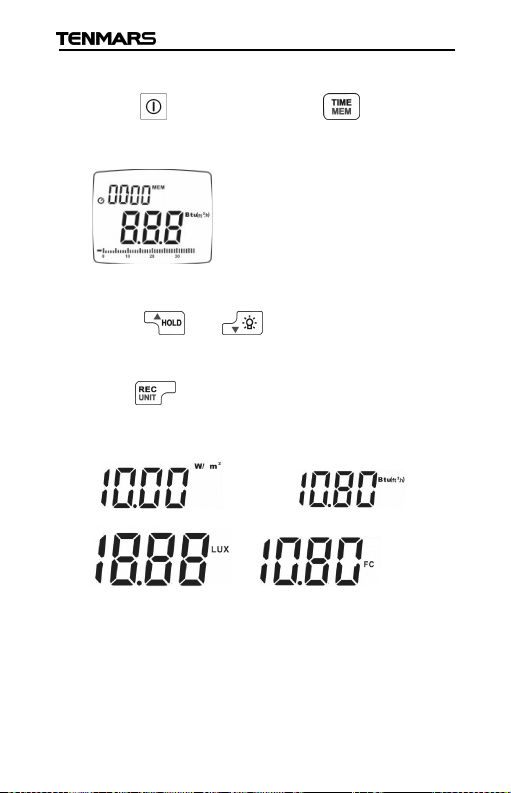
Press button to turn on or turn off the power.
8.1. Unit Select
Hold “ ” buttonand Press “ ”button to
change the unit of W/m
Lux or Fc.
8.2. Data hold (HOLD)
Press to enable or disable the data hold
function.
8.3. ZeroAdjustment
Press “ ” button and attach Cap on the sensor.
0.00 will appear on the LCD. Make sure that the
cap is attached on the sensor.
If the zero adjustment has not been made
correctly,some digits will appear on the LCD
instead of 0.00, and the word “Cap” will also
2
or Btu (ft2*h) /
appear on the LCD to inform you that the cap is
covered completely on the sensor.
Page 15
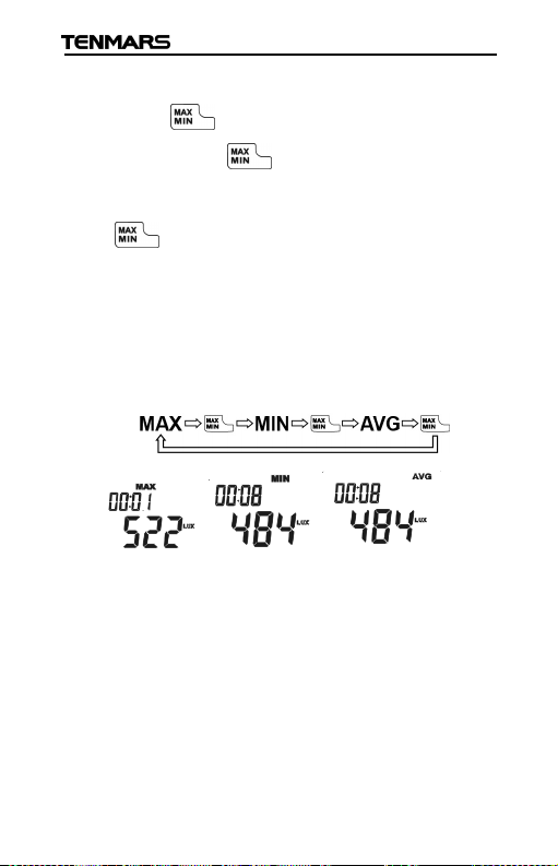
8.4. MAX/MIN/AVG hold:
Press “ ” to enable MAX /MIN/AVG function;
again, press “ ” to show theMAX or MIN
or average values by turns. Press and hold
“ ” for more than 2 seconds to quit.
The measured data can be held and updated as
the measured the MAX. and MIN. and average
values.
Follow the figure circles.
TM-208A
12
Page 16
TM-208A
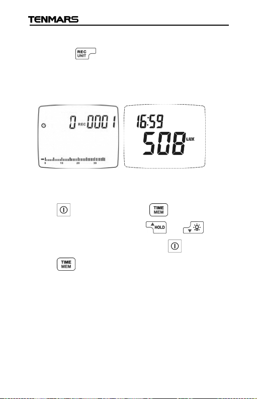
8.5. Manual Record
Press“ ”button, the meter will save the
current measured result, and REC will also
appear on the LCD.
8.6. Manual Record Reading
Hold “ ” button and Press “ ”button “MEM”
appears on the LCD,Press or to select
the log number for reading, Hold “ ” button and
Press “ ”button to quit this mode.
13
Page 17
TM-208A
8.7. Disable Auto Power Off
Please hold “ ” button and Press “ ” button,
the auto power off symbol will not display on the
LCD.
If you want enable auto power off pleasehold
“ ” button and Press “ ” button again.The
auto power offsymbol will display on the LCD.
Auto power offtime is 30 minutes.
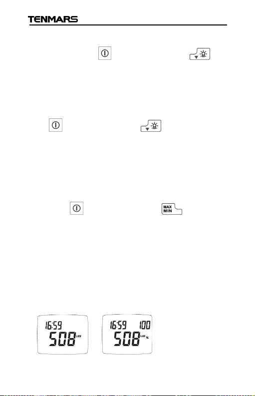
8.8. Relative Deduction Value (%)
Hold “ ” button and Press “ ” button into
the setup mode to save the current measured
result (=100% transmission), and then the
current measured result will be divisorby the next
measured result, and the diff erence from the
divisor will appear RATE on the LCD.
%:
14
Page 18
TM-208A
The transmission percent is= (second measured
value/first measured value) x100
Hold “ ” button and Press “ ” button again
to exit RELmode.
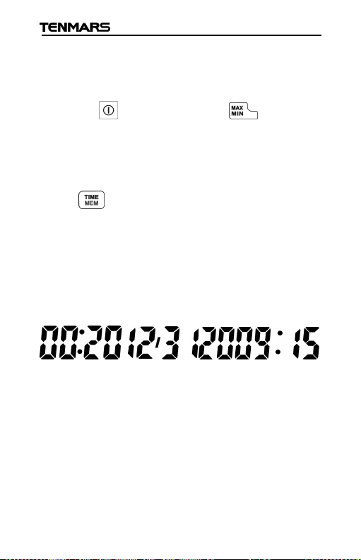
8.9. Clock LCD Display
Press button for more than seconds to select
the display method of the Year, Month, Date, hour
and Second.
This meter’s clock uses 24-hour time setting.
Default time mode setting is “2010/01/07 00: 02”
“:00”.
15
Page 19
TM-208A
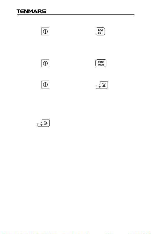
8.10. Setup Mode
Hold “ ” button and Press “ ” button into the
setup mode to use Auto Recording time setup or
Time setup function.
Hold “ ” button and Press “ ” button to view
records.
Hold “ ” button and Press “ ” button to
disable Auto power off.
8.11. Turn on backlight
Press to turn the backlight on or off.
If connected via an external power supply, the
backlight will light automatically and stayon.
The backlight will automatically turn off after
being lit for 30 seconds.
16
Page 20
TM-208A
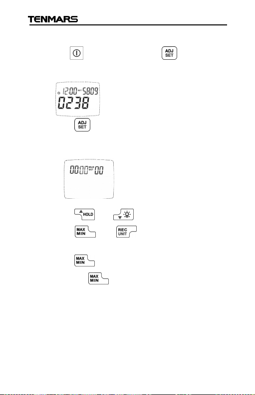
8.12. Auto Recording Time Setup
Hold “ ” button and Press “ ” button into the
setup mode to change setup function.
Press “ ” button again intoAuto Recording
Time Setup.
Min:
Press “ ” or “ ” button to change digit
Press “ ” or “ ” to select option to
adjust
Press “ ” button to skip from minute to hour
and press“ ” button one more time, itwill skip
to second, and so far so on. (Min→Hour →
Sec). .
17
Page 21
TM-208A
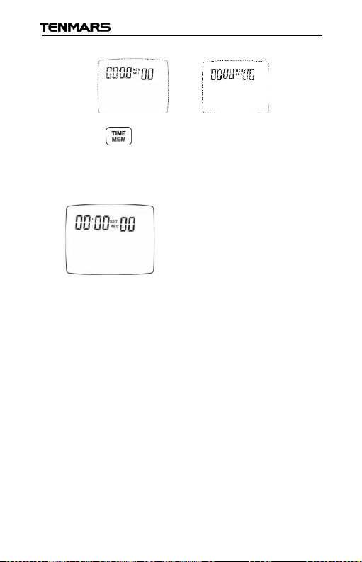
Hour: Sec:
Press “ ” button to store thesetting.
If you do not want to use autopower off,you can
set auto power off time to be 00:00 00.
Maximum auto recording time: 23 hours 59
minutes 59 seconds.
Minimum auto recording time: 1 second.
18
Page 22
TM-208A
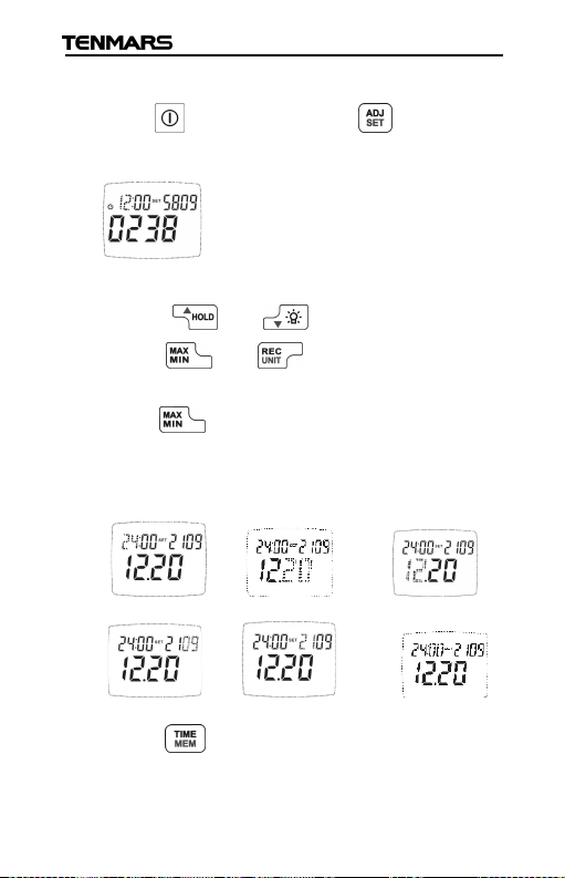
8.13. Time clock Setup
Hold “ ” button and Press “ ” button to
change time setup mode.
This meter clock is 24-hour time setting.
Press “ ” or “ ” button to change digit
Press “ ” or “ ” to select option to
adjust
Press “ ” button toskip from hour to day, and
day to month, and so far so on.(Hour→day→
Month→year→Sec→Minute).
Hour: day: Month:
Year: Sec: Minute:
Press “ ” button to store thesetting.
Years time 2000~2099:display 00 ~ 99
19
Page 23
TM-208A
8.14. Viewing Records
Hold “ ” button and Press “ ” button to view
records.
Press“ ” or “ ” button to scroll through
the records.
Press“ ” to change (BTU (ft
BTU (ft2*h)) / (FC→LUX→ FC)unit.
2:
W/m
Lux: Fc:
Btu(ft2*h):
2
*h) → W/m
2
→
20
Page 24
TM-208A
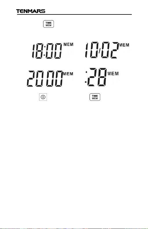
Press “ ” button to change time data (H:M→
M:D→year→ sec).
H:M M:D
year sec
Hold“ ”button and Press“ ”button again to
exit viewing records mode.
8.15. Computer Grade
CPU:Pentium Ⅲ 1000MHZ.
RAM:SDRAM 256MB.
Hard Disk:200MB.
OS:XP/Windosw7/Windows 8.1/Windows10.
Display: 800×600 256 cooler.
21
Page 25
TM-208A
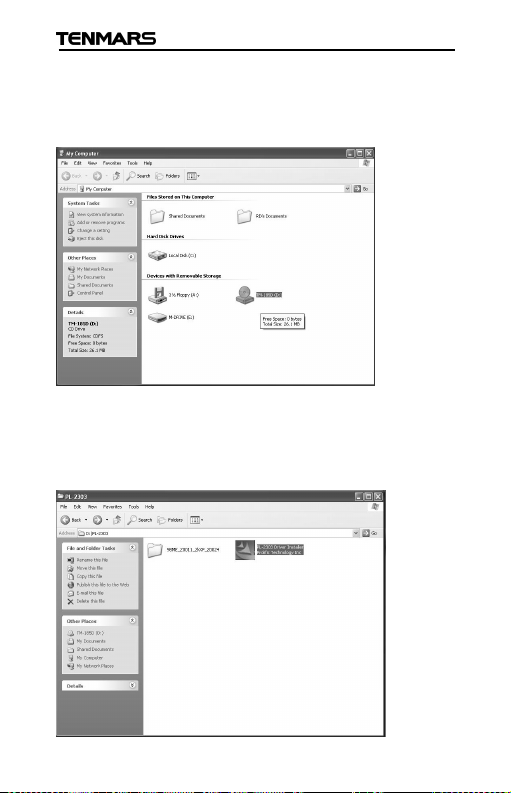
9. Software installation
Please insert the CD into PC to install the
software.
Please selectthe USB driver that will be installed,
such as E:\ Light Meter Driver Setup.exe, click
twice on the left key of the mouse to install the
USB driver.
22
Page 26
TM-208A
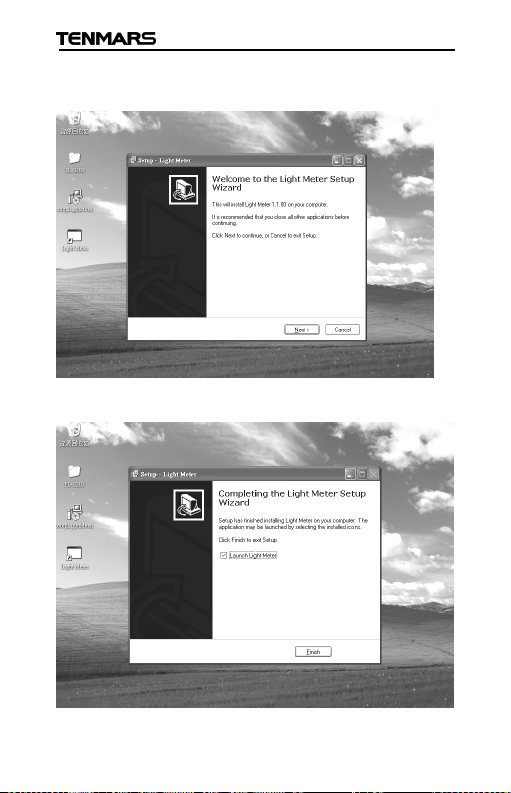
Select the SETUP.EXE i.e., E:\Light
Metre\SETUP.EXE and installs the desktop icon
Tack out the CD from PC after completed the
installation of the desktop icon.
23
Page 27
TM-208A
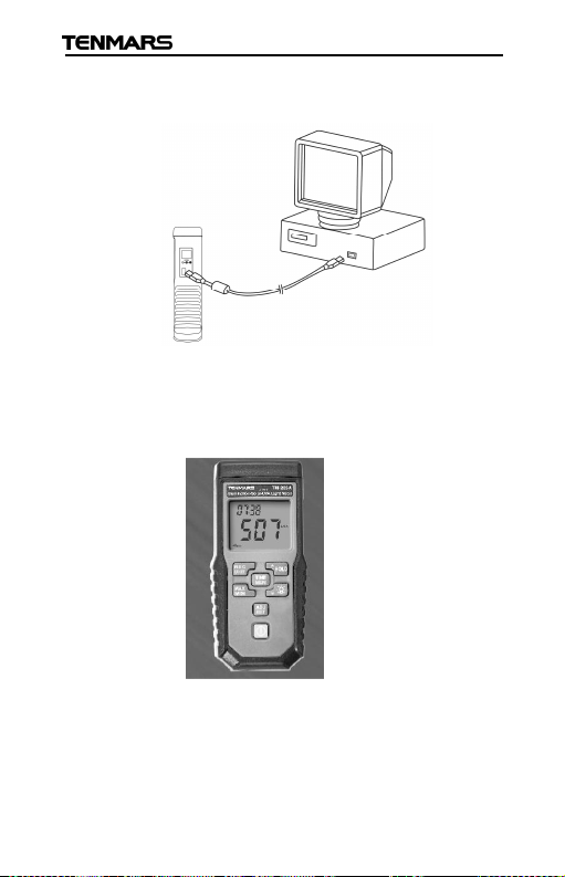
Use the USB cable to connect the meterand
computer according to the drawing.
Select the desktop icon (Light Meter) and click
twice on left key of the mouse to run the
procedure.
24
Page 28
TM-208A
10. Maintenance or Repair
1.When the When “ ” symbol is displayed on the LCD,
it means that there is insufficient power; please change
the battery immediately in order to ensure its accuracy.
2.Do not place the meter in locations that have high
temperature, humidity or that are exposed to direct
sunlight.
3.Remember to turn off the power after usage; remove
the battery if not used for a long period of time in order
to prevent battery leakage and causing damages to
internal components.
4.When the instrument failure, only by the authorized
service provider or return the original repair.
11. PRECAUTIONS
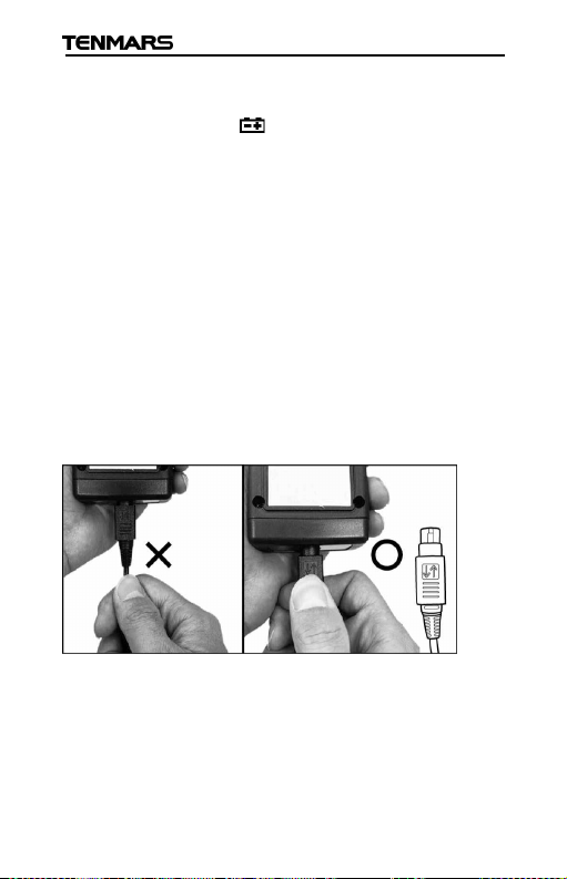
Removing Probe (With LOCK) :
25
Page 29
12. Battery Replacement
WARNING
If the LCD display “ ” symbol, please
replace the battery immediately.
1. Turn off the power.
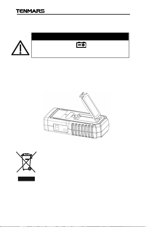
2. Open the battery cover at the back of the meter,
remove the batteries.
3. Please insert new 9V batteries according to the
polarities.
4. Put the battery cover back in place.
13. Product Disposal:
Note: This symbol indicates that the
meter and its accessories must be
separated and processed properly.
TM-208A
26
Page 30

Page 31

Page 32

Professional Electrical and
Environment Test & Measurement
Instruments:
Battery Capacity / Impedance Tester, TACHO
Meter, LED light meter, Temperature & Humidity
meter, Infrared Thermometer, Sound level
meter, Light meter, EMF meter, UV Light meter,
RF meter, Hot wire Anemometer, CO meter
Anemometer, Lan cable tester, CO2meter,
Solar power meter, Radiation meter,
Clamp meter, Multimeter, Phase Rotation test,
Digital Insulation tester
Our products of high quality are selling
well all over the world
TENMARS ELECTRONICS CO., LTD
6F, 586, RUI GUANG ROAD, NEIHU,
TAIPEI 114, TAIWAN.
E-mail: [email protected]
http://www.tenmars.com
 Loading...