

Page 1
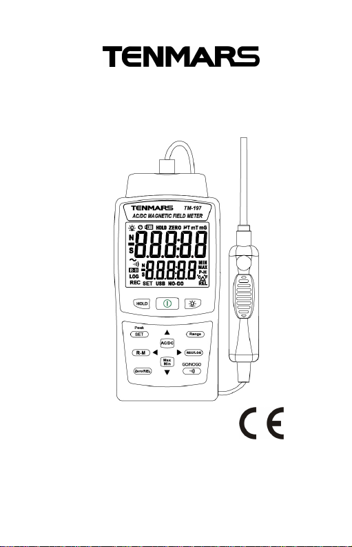
AC/DC Magnetic Field Meter
TM-197
User Manual
HB2TM1970002
Page 2

Page 3

Contents:
1 Introduction..............................................................1
2 Accessories..............................................................1
3 Safety Precaution:...................................................2
4 Instrument Description:...........................................3
5 Operation:.................................................................4
5.1 Zeroing................................................................5
5.2 Peak Measurement...........................................5
5.3 Relative Value Measurement...........................6
5.4 Turn on backlight...............................................6
5.5 Manual Record for One Log.............................6
5.6 Auto Record.......................................................6
5.7 Read the record data from RAM......................7
5.8 Data Hold............................................................7
5.9 The Max./Min. Values Hold:.............................7
5.10 Disable Auto Power Off Function:...................7
5.11 Stopping buzzer.................................................7
5.12 Manual range mode/Automatic range mode..8
5.13 AC/DC Switching magnetic field......................8
5.14 Setup:Step 1~ Step 8.....................................8
6 Software Installation: ............................................10
7 General Specifications:.........................................11
8 Electrical Specification:.........................................13
9 Maintenance or Repair.........................................14
10 Battery Replacement............................................14
11 PRECAUTIONS.....................................................14
12 End ofLife Disposal..............................................15
Page 4

TM-197
1
1
Meter
1
AC/DC
1
User’s Manual
6
Battery 1.5V(UM4/AAA)
1
Carrying case
1
Power adapter DC 9V
1
USB cable and Installation di
1 Introduction
Measurement for the magnetic field generated from Direct
Current (DC, with display by N/S Magnetic polarity) or
Alternating Current (AC in 40-500Hz).
Measurement for the residual magnetic after processing
of mechanical parts
Measurement for the magnetic field strength of magnetic
applications
Measurement for the residual magnetic generated from
the stress after processing of stainless material
Measurement for the magnetic force of magnetic
materials
Measurement for the various steel materials with natural
magnetism
Measurement for the magnetic field strength of motors in
various electrical appliances
Measurement for the magnetic field strength of permanent
magnets
Detection for the magnetic field of leakage generated from
superconductive magnets
2 Accessories
magnetic probe
sk
Page 5

TM-197
2
3 Safety Precaution:
Caution! Please refer to this manual.
Improper use may damage the meter and
its components.
Complies with European Directive.
Do not operate in environments with flammable gas or
humid environments.
Operating altitude: up to 2000M.
Operating environment: Indoor use; Pollution degree 2.
Clean with soft cloth when dirty, such as glasses cloth.
Do not clean with chemicals and other solvents.
EMC: EN61326-1:CISPR 11:Group 1, Class B
Class B – Equipment for use in all establishments other
than
domestic.
Group 1 – RF energy generated is needed for internal
functioning.
Page 6
TM-197
3
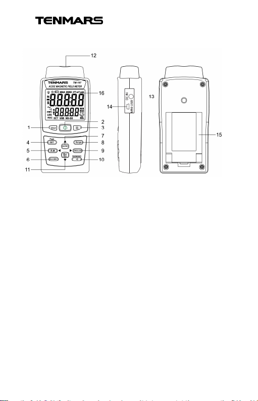
4 Instrument Description:
1. Data hold
2. Power
3. Backlight button
4. SET/Peak value hold
5. Read the record data from RAM (R-M)/Left
6. Set to Zero (Zero)/ Relative Value (REL)
7. AC/DC switch/Up
8. Manual range mode/Automatic range mode
9. Manual record (REC)/ Auto record (LOG)
10. Buzzer/GO & NO-GO
11. The max. & min. value hold/Down
12. Probe connector
13. External power DC 9V input
14. USB dataoutput jack
15. Battery cover and tilt stand
16. LCD display
Page 7
TM-197
4
again, turn power on.
for warni
ng.
5 Operation:
1. Press to turn on or turn off.
2. Remove the cap of probe.
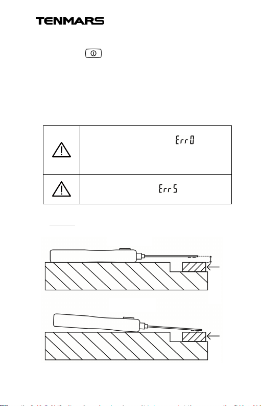
3. Move the HALL ELEMENT which is located on
the tipof probe close to the magnet under test
and start measuring. Please refer to Fig. 1.
4. Read the measured value from the LCD
display.
5. Cover the cap of probe back.
If the probenot inserted intothe host or
not insertedcompletely, , will
appear. Please turn power off and
ensure to insertthe probe into the host;
If the probe isdisconnected with the
host whileworking, will appear
Fig. 1
Correct
Incorrect
Magnet
Magnet
Page 8
TM-197
5
PC)
HOST)
temperature.
measuring.
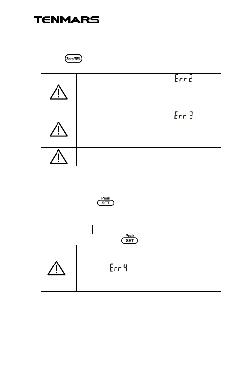
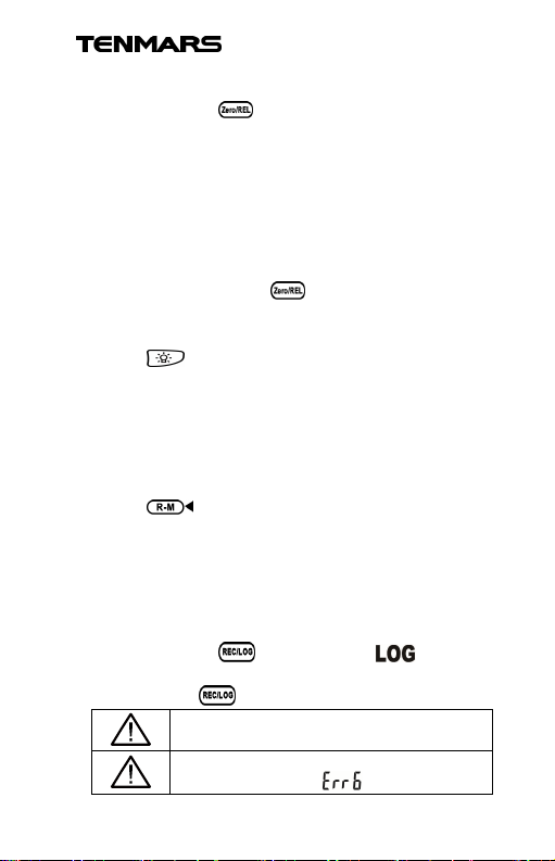
5.1 Zeroing
Move the probe away from the magnetic field and
press , ZEROwill appearon the LCD. After
zeroing completed, the ZERO disappears.
If morethan 3G or 0.3mT, will
appear to prevent from erroneous
zeroing the value in measuring. (from
If morethan 3G or 0.3mT, will
appear to prevent from erroneous
zeroing the value in measuring. (from
The zeroing function is unavailable for
5.2 Peak Measurement
Move the probe away from the magnetic field, then
press andhold for ≥2 seconds to start Peak
Measurement. The upper digit row presents the
instant measuring; the lower digit row presents the
peak value x.x
Again, press andhold to quitthis function.
Zeroing will run automatically in prior to
Peak Measurement. Ifmore than 3G or
0.3mT, will appear to prevent
from erroneous zeroing the value in
Page 9
TM-197
6
connection.
recording in logs,
will appears.
5.3 Relative Value Measurement
Press andhold for ≥2 seconds to start
Relative Value Measurement.
The difference between the two magnetic fields can
be compared here. For instance, the 1stmagnetic
field ismeasured to be 100. At the time, press
“REL” button, and the LCD displays 0; again,
measure the 2ndmagnetic field. If the measured
value ofthe 2ndmagnetic field is 120, the LCD will
display 20 (120-100=20).
Again, press andhold to quitthis function.
5.4 Turn on backlight
Press to turn the backlight on or off.
If connected via an external power supply, the
backlight will litautomatically and stay on.
*The backlight will automatically turn off after
being lit for 30seconds.
5.5 Manual Record for One Log
Press to save one log of data, the LCD will
show “REC” and the numberof logs. For instance, if
the currentnumber is 10, it will be increased by 1 at
each pressing. Thenumber of logs is limited to be
200; if exceeded, the LCD will show “Full”.
5.6 Auto Record
Press andhold , LCDdisplays , and the
auto-recording function is enabled.
Again, press to quitthis function.
The record is setup on PC via USB
If the power isinsufficient when
Page 10
TM-197
7
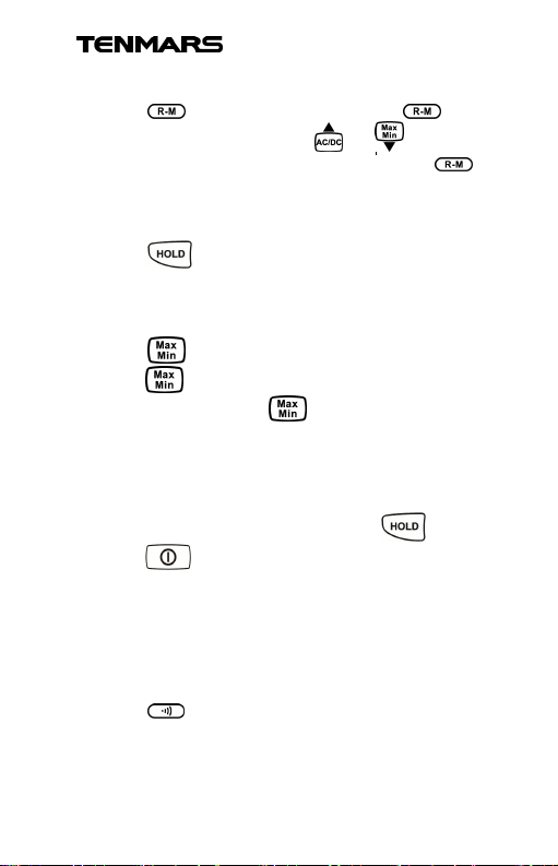
5.7 Read the record data from RAM
Press for the reading mode, and
appears on the LCD. Press or to select
the log number for reading. Press and hold to
quit thismode.
5.8 Data Hold
Press to enable or disable the data hold
function.
5.9 The Max./Min. Values Hold:
Press to enable MIN/MAX function; again,
press to show the MAX and MIN values by
turns. Press and hold to quit.
The measured data can be held and updatedas the
measured the MAX and MIN values.
5.10 Disable Auto Power Off Function:
With poweroff mode, keep pressing and
press to turn on power, LCD will show
"n-SL" that means to disable auto power off function.
Re-starting will reset to the auto power off function.
The function will be disabled when an external
power is detected.
5.11 Stopping buzzer
Press to stop the buzzer’s beep.
Page 11
TM-197
8
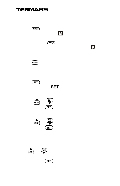
5.12Manual range mode/Automatic range
mode
Press to operate in the manual range mode
with the LCD showing . This can change into two
different range modes.
Press andhold for ≥ 2 seconds to return to
automatic range mode with LCD showing .
5.13AC/DC Switching magnetic field
Press to switch the measurement betweenAC
magnetic field and DC magnetic field.
5.14Setup:Step 1~ Step 8
Press to enter the setup procedure from step
1 to step 8, while flashes on the LCD.
Step 1. Setup unit G or mT.
1. Press or to selectthe unit G or mT.
2. Again, press to go to Step 2.
Step 2. Setup unit °C or °F
1. Press or to selectthe unit ºC or ºF.
2. Again, press to go to Step 3.
Step 3. Set up the upper limit (Max.) for alarm
GO/NO-GO
1. The default value is 20000G (2000.0mT). Press
or to modify and setup the default
value.
2. Again, press to go to Step 4.
Page 12
TM-197
9
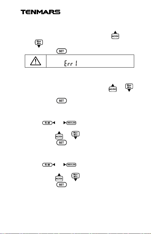
value,
appears.
Step 4. Set up the lower limit (Max.) for alarm
GO/NO-GO
1. The default value is 0G (0.0mT). Press or
2. Again, press to go to Step 5.
Step 5. Setup the measurement interval of alarm
GO/NO-GO
1. The default value is 2 seconds. Press or
2. Again, press to go to Step 6.
Step 6. Setup year/month/date
1. Go to the mode to setup the year/month/date.
2. Press or to select the item to
3. Then, press or to correct the value.
4. Again, press to go to Step 7.
Step 7. Setup hour/minute:
1. Go to the mode to setup the hour/minute.
2. Press or to select the item to
3. Then, press or to correct the value.
4. Again, press to go to Step 8.
to modify and setup the default value.
If themin. value is more than the max.
to modify andsetup the default value.
modify, the digits of the selected item will flash.
modify, the digits of the selected item will flash.
Page 13

TM-197
10
Step 8. Clear the manual record:
1. Go to the mode to clear the manual record LCD
shows .
2. Press or to select or where the
default value is 。
3. If the record is not cleared, press again to
return to the measurement mode when the LCD
shows .
4. If is selected, press to returnto the
measurement mode and clear the record while
LCD shows "CLEAR".
6 Software Installation:
1. Link website https://www.tenmars.com/
2. Click English in the upper right corner of the
web page.
3. Search TM-197.
4. Click on the TM-197 photo.
5. Click File Download, then select Software
Download.
6. Download and unzip the software.
7. For the latest software information and
installation procedures, Please download the
software instructions.
Page 14

TM-197
11
7 General Specifications:
Liquid crystaldisplay (LCD) of 5 digits with the
displaying value up to 30000.
Backlight display. The backlight is manually
turned on (itwill turn offautomatically after turned
on for 30 seconds) and turned off. If connected
via anexternal power supply, the backlight will lit
and stay on;it will turn off until the external power
supply disconnected.
Enable anddisable auto power off function
(default 15 minutes).
Measurement range: 0~3000mT (milli Tesla)
/0~30000G (Gauss); Auto Range function (with
Automatic Measurement).
Conversion ofunits: 1mT (milli Tesla) = 10G
(Gauss)
Relative value/Peak hold/Real time Zeroing
function.
Enable anddisable auto power off function
(default power off is 15 minutes from the last
operation).
DATAHOLD(Data hold)
MAX/MIN (Maximum hold/ Minimum hold)
The GO andNO-GO alarmfunction and its
settings that can be applied to detect good and
defective products on the production line.
Unitswitch for Gauss/Tesla.
The maximum, minimum, and average values:
auto exportthe top 10 max./top 10 min./ average
values based on the data which is recorded and
downloaded to the computer.
As connected to a PC, press REC to record the
real-time data in the PC.
Overloaddisplay: “OL”.
Manual recording: up to 200 logs.
Page 15
TM-197
12
Automatic recording: up to 7000 logs where the
record interval shall be setup with PC.
" ":detection for battery low
Battery life: Approximately 100 hours.
Operation temperature and humidity: 5°C to 40°C (41°F
to 104°F), < 80%RH。
Storage temperature and humidity:0°C to 50°C, relative
humidity under 70%.
Weight: Approximately 320 grams (with battery)
Dimensions: 156 (L) x 73 (W) x 35 (H) mm
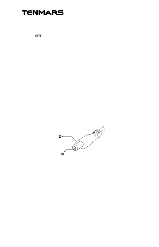
AC to DC Adaptor
External AC 100~240V to DC 9V/0.5A power
supply
Plug: The pin in the center connects to the
positive electrode and the outer case is negative
electrode
Diameter: 5.5mm; internal diameter: 2.1mm
Page 16
TM-197
13
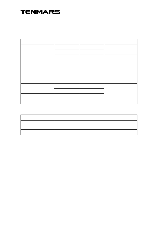
Specifications
Range
Resolution
Accu
racy
300.00 mT
0.01 mT
2000.0 mT
0.1 mT
3000.0 mT
3000.0G
0.1G
20,000G
1G
150.00mT
0.01 mT
1500.0mT
0.1 mT
1500.0G
0.1G
15,000G
1G
-
20~50
°C/-4~122
°
F
±1.0°C/±1.8°F
8Electrical Specification:
Accuracy is indicatedas [% rdg + dgt] at 23°C ± 5°C
with RH< 80%.
±(4% + 10dgt)
DC milli Tesla
DC Gauss
AC milli Tesla
AC Gauss
Temperatures:
Range
Resolution
Tolerance
2000.1 ~
20,001 ~
30,000 G
0.1 mT N/A
1G N/A
±0.1°C / ±0.1°F
±(4% + 10dgt)
±(5% + 20dgt)
Page 17
TM-197
14
9Maintenance or Repair
1.When the When “ ” symbol is displayedon theLCD,
it means that there is insufficientpower; please
change the batteryimmediately in orderto ensure its
accuracy.
2.Do not place the meter in locations that have high
temperature, humidity orthat are exposed to direct
sunlight.
3.Remember to turn off the power after usage; remove
the battery if not used for a long period of time in
order to preventbattery leakage andcausing
damages to internalcomponents.
4.When the instrumentfailure, only bythe authorized
service provider orreturn the originalrepair.
10Battery Replacement
1. Turn off the power.
2. Open theframe and battery cover at the back of the
meter, remove the batteries.
3. Insert6 pcs ofnew AAA1.5V batteries according
to thebattery polarity.
4. Put thebattery cover and frame back in place.
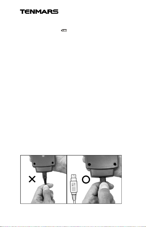
11PRECAUTIONS
Removing Probe (With LOCK) :
Page 18

TM-197
15
12 End of Life Disposal
Note: This symbol indicates that the meter
and its accessories must be separated and
processed properly.
Page 19

TM-197
16
Page 20

Professional Electrical and
Environment Test & Measurement
Instruments:
Battery Capacity / Impedance Tester
LED light meter, Temperature & Humidity meter,
Infrared Thermometer, Sound level meter
Light meter,EMF meter, UV Light meter,
RF meter, Hot wire Anemometer, CO meter
Anemometer, Lan cable tester, CO2meter,
Solar power meter, Radiation meter,
Clamp meter, Multimeter, Phase Rotation test,
Digital Insulation tester
Our products of high quality are
selling well all over the world
TENMARS ELECTRONICS CO., LTD.
6F, NO.586 Ruiguang Rd, Neihu Dist.
Taipei City, Taiwan
E-mail: [email protected]
http://www.tenmars.com
 Loading...