

Page 1
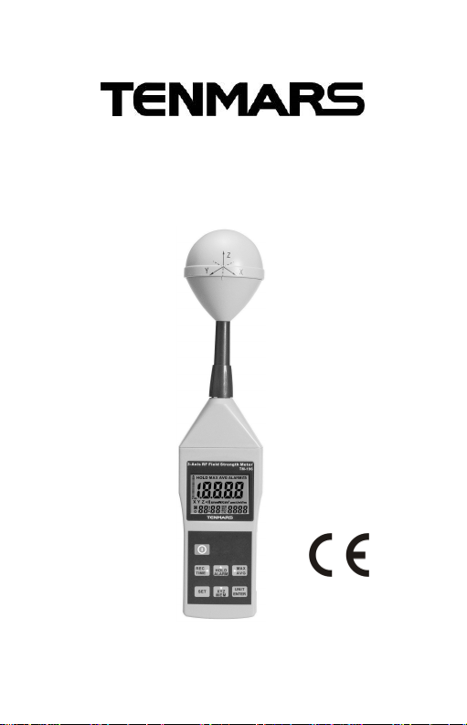
RF three-Axis
Field Strength Meter
TM-196
User’s
Manual
HB2TM1960007
TENMARS ELECTRONICS CO., LTD
Page 2

Page 3

Table of Contents
Axis RF Meter Quick Start Guide .................................1
1 Introduction..........................................................2
2 Simple a Method of Operation..............................2
3 Fundamentals......................................................3
4 Electric Field Strength (E) ....................................3
4.1 Magnetic Field Strength (H)...........................3
4.2 Power Density (S)..........................................4
4.3 The Characteristic of Electromagnetic Fields .4
5 Application...........................................................5
6 Features ..............................................................6
7 Identifying Parts...................................................8
8 LCD Description...................................................9
9 Specifications.....................................................10
9.1 General specifications .................................10
9.2 Electrical Specifications...............................12
9.3 Units of Measurement..................................13
9.4 Result modes...............................................14
9.5 Measurement Procedures and Preparation..15
9.6 Power key: ................................................15
9.7 Data Hold Key: ............................................16
9.8 Units Key:....................................................16
9.9 MAX / AVG Record:.....................................17
9.10 Manual data memory storing .......................17
9.11 XYZ/CALL:...................................................18
9.12 Alarm ON/OFF Setup..................................18
9.12. 1Viewing Data Records ..............................19
9.13 Cancel the automatic power off/on :.............19
9.14 Clock LCD Display.......................................20
Page 4

TM-196 TM-196
10 Setup Mode......................................................20
10.1 Clock Setup-1..............................................21
10.2 Setting the alarm limit value (ALARM)-2......22
10.3 DEL data logger memory setup-3 ................23
10.4 Analogue bar graphsetup-4.........................24
10.5 Auto Power Off Time function setup-5..........24
10.6 Setting the calibration factor (CAL)-6 ...........25
11 Calibration factor is important for the measurements:
..........................................................................26
11.1 Short-term measurements: ..........................27
11.2 Short-term measurements ...........................27
11.3 Long-term exposure measurements ............28
12 Battery replacement...........................................29
13 External DC Power ............................................30
14 Safety Precaution...............................................30
15 Safety Information..............................................31
16 Safety Information..............................................32
17 End of life...........................................................33
Page 5

TM-196 TM-196
Axis RF Meter Quick Start Guide
This meter has many capabilities, including
memory, alarm, date/time, average etc.
which will require some study of the manual
to use properly. However, you can quickly
and easily begin making measurements
right out of the box. Just follow these simple
steps:
1. Insert 9V battery.
2. Turn meter on with GREEN button.
3. Press XYX/MEM button until all three
(XYZ) letters are displayed on the screen
(to the left of the main number.
4. Press UNIT/ENTER button until the
desired units are displayed below the
main number (we recommend using
mV/m… and we recommend a maximum
level of 614 mV/m for prolonged
exposure).
You are now ready to make your first
measurements!
EN-1
Page 6

TM-196 TM-196
1 Introduction
This meter is designed for measuring and
monitoring Radio–Frequency electromagnetic
field strength. The meter is calibrated precisely
over the frequency range of 10MHz~8GHZ.
2 Simple a Method of Operation
Press “power” button on.To change measuring
unit (mV/m), push UNIT”button to change the
unit.Electric field strength (V/m).Computed
magnetic field strength (mA/m).Computed
power density (mW/m2).Computed power
density (μW/cm
Press "xyz” this key to change sensor axis
selector:
“All axis ” → “X axis” → “Yaxis” → “Z
axis”.
2
).
EN-2
Page 7

TM-196 TM-196
3 Fundamentals
Electromagnetic Pollution
This meter is used to indicate electromagnetic
pollution generated artificially. Wherever there
is a voltage or a current, electric (E) and
magnetic (H) fields arise. All types of radio
broadcasting and TV transmitters produce
electromagnetic fields, and they also arise in
industry, business and the home, where they
affect us even if our sense organs perceive
nothing.
4 Electric Field Strength (E)
Afield vector quantity that represents the force
(F) on an infinitesimal unit positive test charge
(q) at a point divided by that charge. Electric
field strength is expressed in units of volts per
meter (mV/m). This meter measures electric
field strength directly.
4.1 Magnetic Field Strength (H)
Afield vector that is equal to the magnetic flux
density divided by the permeability of the
medium Magnetic field strength is expressed
EN-3
Page 8

TM-196 TM-196
in units of amperes per meter (A/m). In far field
situations, one can calculate the magnetic field
for the electric field value. This meter can
display the calculated magnetic field strength.
4.2 Power Density (S)
Power per unit area normal to the direction of
propagation, usually expressed in units of
watts per square meter (W/m2) or, for
convenience, units such as mill watts per
square centimeter (mW/cm2)
4.3 The Characteristic of Electromagnetic
Fields
Electromagnetic fields propagate as waves
and travel at the speed of light (C). The
wavelength is proportional to the frequency.
λ (wavelength) = C (speed of light) /
f (frequency)
If the distance to the field source is less than
three wavelengths, then we are usually in the
near field. If the distance is more than three
wavelengths, the far-field conditions usually
hold.
In near field conditions, the magnetic field value
EN-4
Page 9

TM-196 TM-196
cannot be calculated from the electric field value.
This meter is designed for reliable far field
measurements only.
5 Application
Quite often routine, maintenance and
service work has to be done in areas where
active electromagnetic fields are present,
e.g. in broadcasting stations, etc.
Additionally, other employees may be
exposed to electromagnetic radiation. In
such cases, it is essential that personnel be
not exposed to dangerous levels of
electromagnetic radiation, such as:
High frequency (RF) electromagnetic wave
field strength measurement.
Mobile phone base station antenna radiation
power density measurement.
Wireless communication applications (CW,
TDMA, GSM, DECT).
RF power measurement for transmitters.
Wireless LAN (Wi-Fi) detection, installation.
Spy camera, wireless bug finder.
Cellular /Cordless phone radiation safety
EN-5
Page 10

TM-196 TM-196
level.
Microwave oven leakage detection.
Personal living environment EMF safety.
6 Features
The meter is a broadband device for
monitoring high- frequency radiation in the
range from10MHz to 8GHz
The non-directional electric field antenna
and high sensitivity also allow
measurements of electric field strength in
TEM cells and absorber rooms.
The unit of measurement and the
measurement types have been selected to
expressed in units of electrical and magnetic
field strength and power density.
At high frequencies, the power density is of
particular significance. It provides a measure
of the power absorbed by a person exposed
to the field. This power level must be kept as
low as possible at high frequencies.
The meter can be set to display the
instantaneous value, the maximum value
EN-6
Page 11

TM-196 TM-196
measured or the average value.
Instantaneous and maximum value
measurements are useful for orientation, e.g.
when first entering an exposed area.
For isotropic measurements of
electromagnetic fields.
Non-directional (isotropic) measurement with
three-channel measurement sensor.
High dynamic range due to three- channel
digital results processing.
Configurable alarm threshold and memory
function.
Easy & safe to use
Low battery detector “ ”.
Manual data memory storing: 200 data sets.
Memory Over load indication “OL”.
EN-7
Page 12
TM-196 TM-196
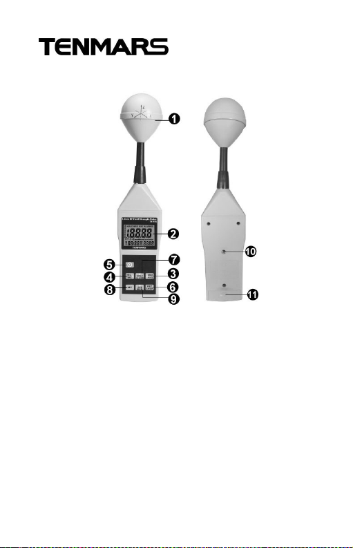
7 Identifying Parts
1. RF three-Axis Sensor.
2. Liquid-crystal LCD.
3. Hold /ALARM / Up Button.
4. MAX / AVG/ Right Button.
5. UNIT / ENTER Button.
6. XYZ / MEM / Down Button.
7. Power Button.
8. REC/ time / Leftward Button.
9. SET Button.
10. Tripod mounting screw.
11. Battery Cover.
EN-8
Page 13
TM-196 TM-196
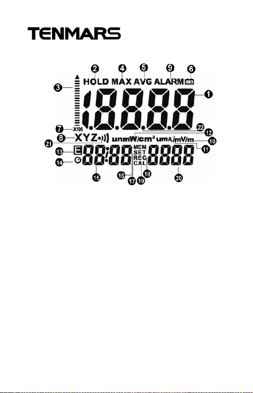
8 LCD Description
1. Primary Display
2. Hold symbol
3. Analogue bar graph
4. MAX symbol
5. AVGsymbol
6. Low battery symbol
7. x1x10x100 unit
8. X.Y.Z unit
9. ALARM sound
10. mV/m, V/m (E)
11. µA/m , A/m unit (H)
12. µW/m2/ µW/cm2unit
13. E Symbol
14. Auto power off symbol
EN-9
15. Time unit
(month: day)
(hour: minute)
(second)
16. MEM reading
symbol
17. SET symbol
18. REC symbol
19. CAL symbol
20. Secondary
Display
21. BUZZER symbol
22. Decimal point
Page 14

TM-196 TM-196
9 Specifications
9.1 General specifications
Display type : Liquid-crystal (LCD), 4-1/2
digits maximum reading 19999.
Measurement method : Digital, Tri axis
measurement.
Directional characteristic : Isotropic,
Tri axis.
Measurement range selection : one
continuous range.
Display resolution : 0.1mV/m, 0.01V/m,
0.1µA/m, 0.1mA/m,0.001µW/ m2, 0.01mW/
m2, 0.001µW/cm2.
Setting time : typically 1.5s (0 to 90%
measurement value.)
Sample rate : 3 times per second.
Audible alarm : Buzzer.
Units: mV/m, V/m, µA/m, mA/m, µW/m
mW/m2, µW/cm
Display value : Instantaneous measured
2
value, maximum value, average value, or
maximum average value.
Alarm function : adjustable threshold with
2
,
EN-10
Page 15

TM-196 TM-196
ON / OFF
Calibration factor CAL : adjustable
Manual data memory and read storage: 200
data sets.
Batteries : 9V NEDA 1604, IEC 6F22 or JIS
006P
Battery life : Approximate 3 hours.
Auto power off : Default time 15 minutes.
Adjustable threshold 0~99 minutes.
Operating temperature range :
0°C to + 50°C.
Operating humidity range :
25% to 75 % RH
Storage temperatures range :
-10°C to +60°C.
Storage humidity range : 0% to 80% RH.
Dimensions : 370 (L)x80(W)x80(H) mm.
Weight (including battery) : Approx.400g.
Accessories : User’s manual, 9V battery,
Carrying case.
EMC
This tester was designed in accordance with
EMC Standards in force and its compatibility
EN-11
Page 16

TM-196 TM-196
has been tested in accordance with
EN61326-1 (2006).
9.2 Electrical Specifications
Unless otherwise stated, the following
specifications hold under the following
conditions:
The meter is located in the far field of a
source; the sensor head is pointed towards
the source.
Ambient temperature : +23 °C ±3°C.
Relative air humidity 25%~75%
Sensor type : electrical field (E).
Frequency range : 10MHz ~ 8 GHz.
Specified measurement range:
CW signal (f >50MHz) : 50mV/m to 11.00
V/m, 53.0µA/m to 28.64mA/m 1µW/m2to
309.3mW/m2, 0µW/cm2to 30.93µW/cm
Dynamic range : Typically 75dB
Absolute error at 1V/m and 2.45GHz:
± 1.0 dB.
Frequency response :
Sensor taking into Account the typical CAL
factor :
2
EN-12
Page 17

TM-196 TM-196
±2.4dB(50 MHz to 1.9 GHz, 3.5 GHz to
8GHz).
±1.0dB (1.9 GHz to 3.5GHz).
Isotropy deviation : Typically ± 1.0 dB
(2.45GHz).
Overload limit : 0.083 mW/cm
per axis.
Overload limit : (0 to 50°C): ± 0.2dB.
9.3 Units of Measurement
The meter measures the electrical component
of the field; the default units are those of
electrical field strength (mV/m or V/m). The
meter converts the measurement values to the
other units of measurement, i.e. the
corresponding magnetic field strength units
(µA/m or mA/m) and power density units
(µW/m2, mW/m2or µW/cm2) using the
standard far-field formulate for
electromagnetic radiation.
2
,(17.7 V/m)
EN-13
Page 18

TM-196 TM-196
9.4 Result modes
The bar graph display always shows the
instantaneous measured dynamic range value.
The digital display shows the result according
to one of three modes, which can be selected.
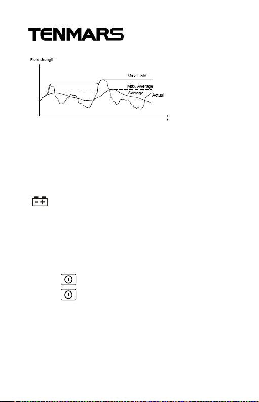
Instantaneous : The display shows the last
value measured value measured by the
sensor, no symbol is displayed.
Maximum instantaneous (MAX) :
The digital display shows the highest
instantaneous value measured, the “MAX
“symbol is displayed.
Average (AVG) : The digital display shows the
average value measured, the “AVG” symbol is
displayed.
Instantaneous mode is the default setting
when the meter is turned on. The following
graph shows of Instantaneous (actual), MAX
(hold), AVG and
EN-14
Page 19
TM-196 TM-196
MAX/AVG:
9.5 Measurement Procedures and
Preparation
Battery loading : Remove the battery cover on
the back and put a 9V battery inside.
Battery replacement : When the symbol of
“ ” appears on the LCD display, the battery
should be replaced with a new one.
The battery symbol will be displayed on the
LCD, this is a battery low indicator.
9.6 Power key:
Press “ ” key turn ON the meter.
Press “ ” key again to turn power OFF.
EN-15
Page 20
TM-196 TM-196
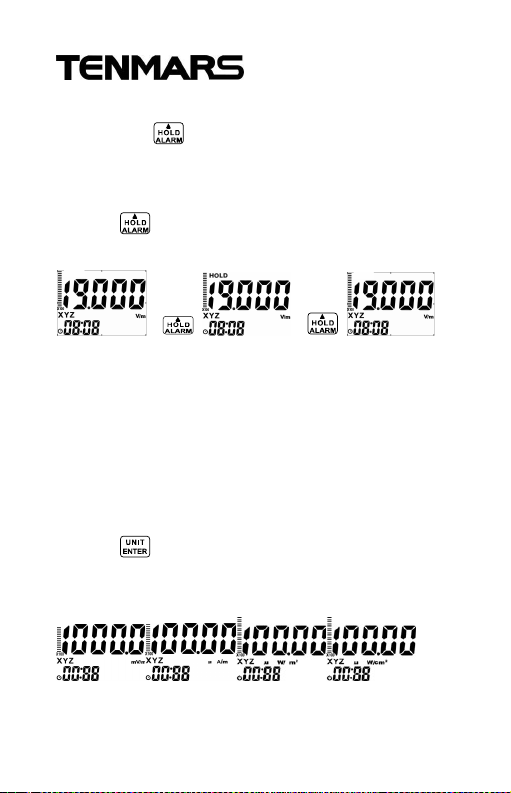
9.7 Data Hold Key:
Press the “ ” key to go into hold mode, and
“HOLD” appears on the screen to allow you to
read the data.
Press “ ” this key once again to deactivate it.
>> > >> >
9.8 Units Key:
Change units with the “UNITS” key as follows
Electric field strength (V/m)
Computed magnetic field strength (mA/m).
Computed power density (mW/m2 ).
Computed power density (μW/cm
Press “ ” key to change the units: mV/m,
V/m, µA/m, mA/m, µW/m2, mW/m2, µW/cm2.
2
).
EN-16
Page 21
TM-196 TM-196
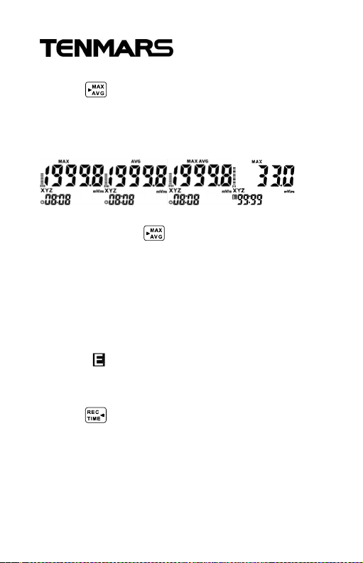
9.9 MAX / AVG Record:
Press “ ” key to switch to the next display.
The display switches from MAX to AVG to
MAX/AVG and back to MAX.
Press and hold “ ”key for 3 seconds to
disable this function.
The maximum storage is up to 99 minutes and
99 seconds
After this period of time, updating will be
completed automatically and then the LCD
displays .
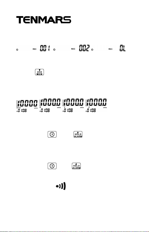
9.10 Manual data memory storing
Press “ ” key,the meter will save the current
measured result, and REC with a number
001~200 will appear.
Manual data memory Storing : 200 data
EN-17
Page 22
TM-196 TM-196
sets.Over load Indication : “OL”.
9.11 XYZ/CALL:
Press “ ” this key to change sensor axis
selector :” All axis ”→“ X axis “→“ Y axis ”→
“ Z axis ”.
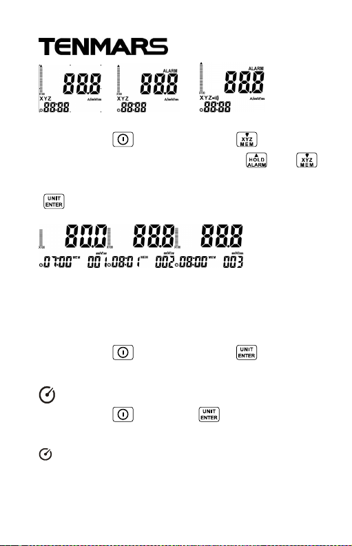
9.12 Alarm ON/OFF Setup
Press hold “ ” and “ ” key to switch the
alarm function on The “ALARM” symbols in the
display indicates that the alarm function is on.
Press hold “ ” and“ ” key to turn off the
alarm function. When the Alarm is ON, the
display shows .
EN-18
Page 23
TM-196 TM-196
9.12.1 Viewing Data Records
Press hold “ ” key and press “ ” key to
view the saved data records Use “ ” or “ ”
key to see the next or previous records Press
“ ” key to close the setup, exit the mode.
9.13 Cancel the automatic power off/on :
The default setting is auto power-off, the time
is set for 15 minutes.
Press hold “ ” key and press “ ” key to
disable the automatic power-off, the symbol of
will be disappeared on the LCD display.
Press hold “ ” key and “ ” key again to
enable the automatic power-on, the symbol of
will be appeared on the LCD display.
EN-19
Page 24
TM-196 TM-196
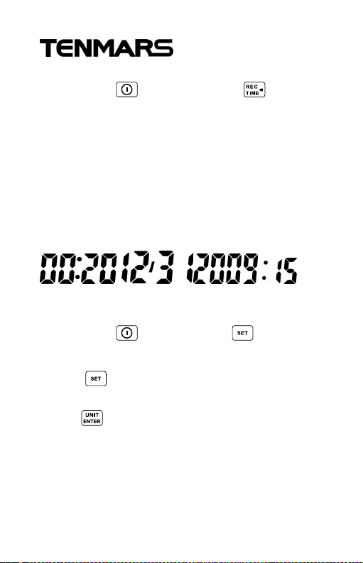
9.14 Clock LCD Display
Press hold “ ” key and press “ ” key for
more than seconds to select the display
method of the Year, Month, Date, hour and
Second.
This meter’s clock uses 24 hour time setting.
Default time mode setting is “2010/01/07 00:
02” “:00”.
10 Setup Mode
Press hold “ ” key first and “ ” button to
enter the Setup Mode.
Press “ ” key to change setup function.
(Setup function see Note1)
Push “ ” key to save setup data
Note1 : you can set up 6 different functions in
setup mode Clock Setup
setup 1 : Setting the alarm limit value
EN-20
Page 25
TM-196 TM-196
(ALARM)
setup 2 : Clear data logger memory
setup 3 : Analogue bar graph X1.X10.X100
setup 4 : Auto Power Off Time
setup 5 : Setting the calibration factor (CAL)
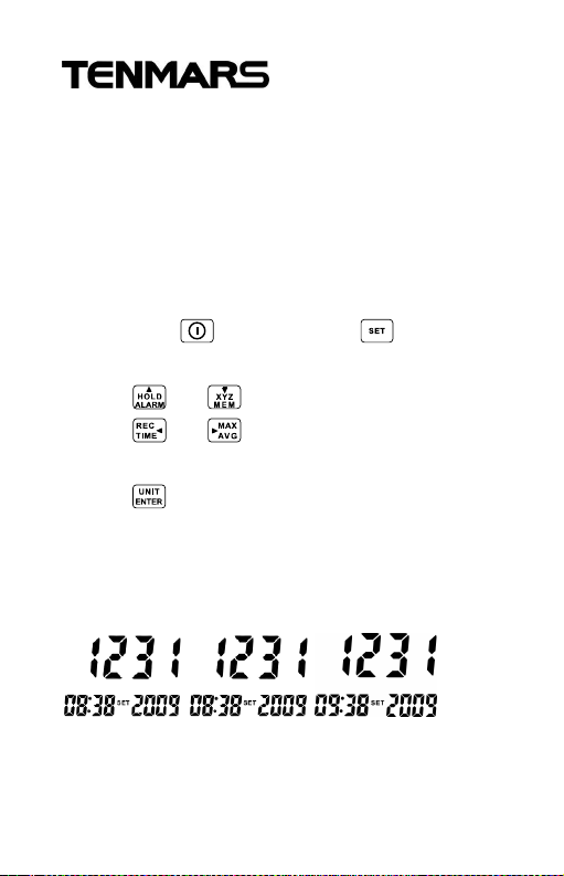
10.1 Clock Setup-1
Press hold “ ” key first and “ ” key to
enter the Setup Mode.
Press “ ”or “ ” key to select option adjust.
Press “ ”or “ ” key to change the date
and time (hour→day→month→year→minute).
Press “ ” key to save and exit.
This meter clock is 24 hour time setting.
Date/Time default Format : 2009/12/21 12:12.
Year Format : 2000~2099 display as 00 ~ 99.
EN-21
Page 26
TM-196 TM-196
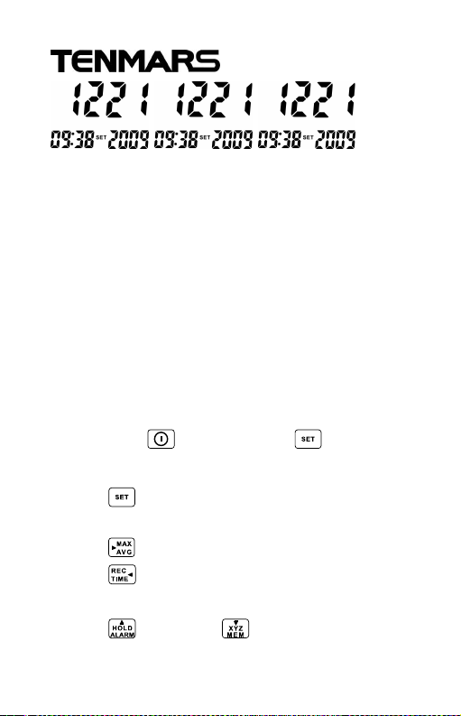
10.2 Setting the alarm limit value
(ALARM)-2
The alarm limit value is used to monitor the
display value automatically. It controls the
alarm indication function. The alarm limit value
can be edited in the displayed V/m unit. The
ALARM setting range is from 0.001 to
999.9V/m. ALARM default is set at 999.9V/m.
Alarm limit function is only used for total three
axial value Comparator.
Press hold “ ” key first and “ ” key to
enter the Setup Mode.
Press “ ” key again to enter the alarm
setting mode.
Press “ ” key to move decimal.
Press “ ” key to select the desired setting
value.
Press “ ” key and “ ” key to change digit.
EN-22
Page 27
TM-196 TM-196
Press “ ” key to select the value.
Press “ ” key to store the new setting value
and exit.
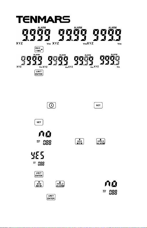
10.3 DEL data logger memory setup-3
Press hold “ ” key first and “ ” key to
enter the Setup Mode.
Press “ ” key twice to enter the default
display ’ ’’, Press “ ” or “ ” key to
select .
Press “ ” key to delete the memory and exit.
Press “ ” or “ ” key to select ’ ’’ and
then press “ ” to keep the memory and exit.
EN-23
Page 28
TM-196 TM-196
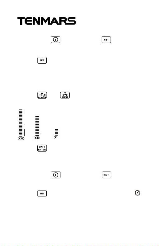
10.4 Analogue bar graphsetup-4
Press hold “ ” key first and “ ” key to
enter the Setup Mode.
Press “ ” key for three times to enter the
analogue bar graph setting mode.
The ”graph” unit is flashing displayed X1、
X10、X100.
Press “ ” or “ ” key to select the value
X1、X10、X100
Press “ ” key to save and exit.
10.5 Auto Power Off Time function setup-5
Press hold “ ” key first and “ ” key to
enter the Setup Mode.
Press “ ” key for four times, the symbol
is displayed.
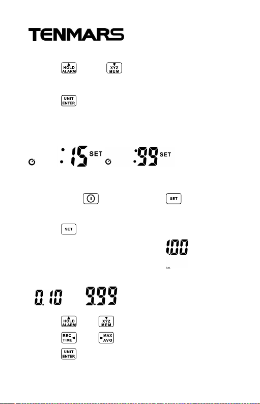
The auto power off time default setting is 15
。
EN-24
Page 29
TM-196 TM-196
minutes.
Press “ “ and “ ” key to change the:
00~99 minutes.
Press “ ” key to save and exit.
: 00 Auto power off disable.
: 99 Maximum auto power off time
10.6 Setting the calibration factor (CAL)-6
Press hold “ ” key first and “ ” key to
enter the Setup Mode.
Press “ ” key for five times to display the
“ CAL SET ” the default factor .
The CAL setting range is from 0.10 to 9.99.
~
Press “ “ or “ “ key to select the value.
Press “ ” or “ ” key to select the digits.
Press “ ” key to save and exit.
EN-25
Page 30

TM-196 TM-196
1.00
1.00
Please refer to the following calibration factors
of our standard meter verified by the
laboratory :
(MHz)(V/m)
1800
2450
X Y Z Average
0.77 0.68 0.85 0.77 1.1
0.94 0.92 0.96 0.94 1.1
(V/m)
11 Calibration factor is important for
the measurements:
The calibration factor CAL serves to calibrate
the result display. The field strength value
measured internally is multiplied by the value
of CAL that has been entered and the resulting
value is displayed. The CAL setting range is
from 0.10 to 9.99.
The CAL factor is often used as a means of
entering the sensitivity of the field sensor in
terms of its frequency response in order to
improve measurement accuracy.
The following effect will be noted with all field
strength meters :
If the sensor is moved quickly, excessive
field strength values could be displayed.
This effect is caused by electrostatic
Factor
(dB)
EN-26
Page 31

TM-196 TM-196
charges.
Recommendation : hold the meter steady
during the measurement.
11.1 Short-term measurements:
Application : Use either the “instantaneous”
or the “Max .instantaneous” mode, if the
characteristics and orientation of the field are
unknown when entering an area exposed to
electromagnetic radiation.
11.2 Short-term measurements
Procedure : Hold the meter at arm’s length.
Make several measurements at various
locations around your work place or the
interested areas as described above. This is
particularly important is the field conditions are
unknown.
Pay special attention to measuring the vicinity
of possible radiation sources. Apart from
active sources, those components connected
to a source may also act as radiators. For
example, the cables used in diathermy
equipment may also radiate electromagnetic
energy. Note that metallic objects within the
EN-27
Page 32

TM-196 TM-196
field may locally concentrate or amplify the
field from a distant source.
11.3 Long-term exposure measurements
Location : Place the meter between yourself
and the suspected source of radiation. Make
measurements at those points where parts of
your body are nearest to the source of
radiation.
Note : Use the “Average” or” Max average”
modes only when the instantaneous
measurement values are fluctuating greatly.
You may fix the meter to a wooden or plastic
tripod.
EN-28
Page 33
TM-196 TM-196
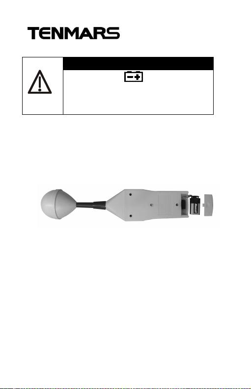
12 Battery replacement
waring
If the symbol “ ” appears on the
LCD, please replace the battery
immediately
Turn off the instrument.
Remove the battery cover
Replace the battery.
Install the battery cover.
EN-29
Page 34
TM-196 TM-196
13 External DC Power
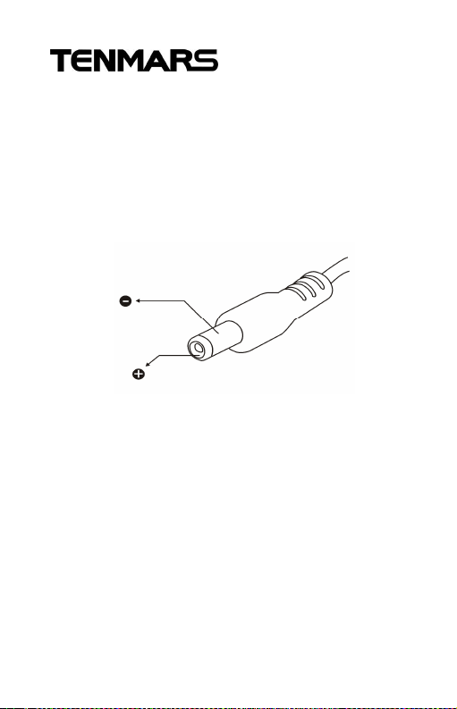
External AC to DC adapter: Voltage
9VDC(8~14VDCMax)
Supply current :>300mADC
Socket : pin Positive, Ground Casing
External
Diameter 6.3mm; internal Diameter 2.0 mm
14 Safety Precaution
For cleaning the instrument use a soft dry
cloth. Never use a wet cloth, solvents or
water, etc.
Operation Altitude : Up to 2000M.
Operating Environment : Indoors use.
This instrument has been designed for being
used in an environment of pollution degree
2.
EN-30
Page 35
TM-196 TM-196
CAUTION
15 Safety Information
Before making a measurement,
check if the low battery symbol”
” is shown on the display as
soon as the meter is switched on.
Change the battery if the symbol is
displayed.
In the case of prolonged storage, it is
preferable to remove the battery
from the meter.
Avoid shaking the meter, particularly
in the measurement mode.
The specified limits outside and
improper handling may adversely
affect the accuracy and function of
the meter.
EN-31
Page 36
TM-196 TM-196
16 Safety Information
DANGER
In some cases, work in the vicinity of
powerful radiation sources can be a
risk of your life.
Be aware that persons with
electronic implants (e.g. cardiac
pacemakers) are subject to particular
dangers in some cases.
Observe the local safety regulations
of the facility operation.
Observe the operating instructions
for equipment, which is used to
generate, conduct, or consumer
electromagnetic energy.
Be aware that secondary radiators
(e.g. reflective objects such as a
metallic fence) can cause a local
amplification of the field.
Be aware that the field strength in the
near vicinity of radiators increases
proportionally to the inverse cube of
the distance. This means that
enormous field strengths can result
in the immediate vicinity of small
EN-32
Page 37

TM-196 TM-196
radiation sources (e.g. leak in wave
guides, inductive ovens)
Field strength measuring device can
underrate pulsed signals. Particularly
with radar signals, significant
measurement errors can arise.
All field strength measuring devices
have a limited specified frequency
range. Fields with spectral
components outside of this
frequency range are generally
incorrectly evaluated and tend to be
underrated. Before using field
strength measuring devices, you
should thus be certain that all field
components to be measured lie in
the specified frequency range of the
measuring device.
EN-33
Page 38

17 End of life
Caution : this symbol indicates
that equipment and its
accessories shall be subject to a
separate collection and correct
disposal
TM-196
Page 39

TM-196
Page 40

TM-196 TM-196
TENMARS ELECTRONICS CO., LTD
6F, 586, RUI GUANG ROAD, NEIHU,
TAIPEI 114, TAIWAN.
E-mail : [email protected]
http : //www.tenmars.com
EN-1
 Loading...