

Page 1
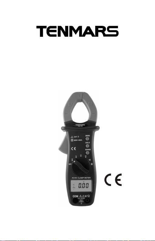
Clamp
-
on meter
TM-12E
TM-13E
TM-13R
HB2TM12E0003
Page 2

Page 3

CONTENTS
1. FEATURES................................................... 3
2. SPECIFICATIONS........................................ 3
3. Instrument Description.................................. 8
4. Measurement.............................................. 10
4.1. Notes........................................ 10
4.2. AC Current (ACA) measurement11
4.3. AC Voltage (ACV) measurement12
4.4. DC Voltage (DCV) measurement12
4.5. DC Current (DCA) measurement13
4.6. Resistance measurements ....... 13
4.7. Continuity test........................... 14
4.8. Frequency Measurement.......... 14
5. Symbols Description ................................... 14
6. Safety precaution........................................ 15
7. Maintenance Notes..................................... 16
7.1. Battery Replacement ................ 16
7.2. Maintenance and Care ............. 17
8. END OF LIFE.............................................. 17
Page 4

TM-12E/13E/13R
1. FEATURES
Thank you for purchasing this instrument. Please read
this instruction manual carefully and completely before
using your digital clamp meter correct operation will
insure the best performance and decrease the
possibility of damages.
*Jaws opening up to 30mm.
* The maximum conductor size is 30mm.
* Safety sockets designed.
* Data Hold.
* Impedance in circuit is below 40. The buzzer will
sound.
2. SPECIFICATIONS
a).Display: 3 3/4 digits LCD with maximum reading
3999, Plus decimal point, unit symbol indication.
b).Polarity Indication: Automatic polarity, “-“ display for
negative input.
c).Overload Indication: LCD will show a “OL” in the left
highest position.
d).Low Battery Indication : Replace battery as LCD
display “BAT”.
e).Battery Life: 50 hours approx.(alkaline battery
recommended)
f).Sampling Rate: 2 times per second for digital display.
20 times per second for analog display.
g).Power Supply: R03(AB)/SIZE AAA 1.5V/UM4 battery
x2.
h).Operation Altitude: up to 2000m.
i).Operating Environment: Indoor use. This instrument
has been designed for use in an environment of
pollution degree 2.
EN-3
Page 5

TM-12E/13E/13R
j).Auto Power Off: The power will be automatically turn
off while the range set is unchanged for more than 30
minutes.
k).Disabling Auto Off: Set the range selector OFF
position to any range and also press down ZERO or
RANGE button.
l).Operating Temperature & Humidity: 5℃ ~ 40℃,below
80%RH.
m).Storage Temperature & Humidity: -10℃ ~ 60℃,
below 70%RH.
n).Safety: IEC61010 and EN61010 (IEC61010-1,
IEC61010-2-031, IEC61010-2-032) CATⅢ 600V.
o).EMC:This apparatus was designed in accordance
with EMC standards in force and its compatibility has
been tested in accordance EN61326 (1997) + A1
(1998) + A2 (2001).
p).Dimension: 195mm(L)x64mm(W)x30mm(H).
q).Weight: About 240g.(including batteries)
r).Accessories: Test Leads、manual、Batteries.
Electrical Specifications:
Accuracy is indicated as [% of reading + digit number].
It is referred to the following reference conditions: 23°C
± 5°C with RH <75%
EN-4
Page 6
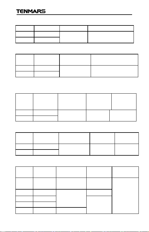
DCA (Auto/Manual)(13E/13R)
Range
Resolution
Accuracy
Overload Protection
40A
0.01A
400A
0.1A
50Hz~
6
0 Hz
40A
0.01A
400A
0.1A
Hz
40A
0.01A
(
3.0%+8
)
50Hz~500 Hz
Impedance
Protection
400V
0.1V
600V
1V
50Hz~500 Hz
Impedance
Protection
40Hz~60 Hz
40V
10mV
400V
100mV
TM-12E/13E/13R
(2.0%+10)
600A rms(60
Second)
ACA (Auto/Manual)(12E/13E)
Range Resolution Accuracy
(2.0%+10)
Overload Protection
600A rms
(60 second)
ACA (Auto/Manual) Ture RMS:From 10% to 100% of
the range(13R)
Range Resolution Accuracy
50Hz~60 Hz
(2.0%+5)
400A 0.1A
Accuracy
65Hz~500
Overload
Protection
600A rms
(60 second)
ACV (Auto/Manual)(12E)
Range Resolution Accuracy
(1.5%+5)
Input
10MΩ
Overload
660V rms
ACV (Auto/Manual)(13E)
Range ResolutionAccuracy
400mV 0.1mV
(1.0%+3)
Input
100MΩ
Overload
DC/AC
660V rms
4V 1mV
(1.0%+3)
11MΩ
10MΩ
600V 1V
(1.2%+3)
EN-5
Page 7
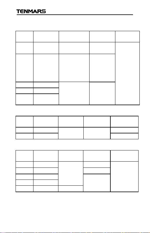
TM-12E/13E/13R
Impedance
Protection
50
Hz~60Hz
40V
10mV
50
0Hz~1KHz
400V
100mV
Impedance
Protection
400V
0.1V
660V rms
600V
1V
Impedance
Protection
40V
10mV
400V
100mV
ACV Ture RMS:From 10% to 100% of the range (13R)
Range Resolution Accuracy Input
Overload
400mV 0.1mV
4V 1mV
(1.2%+40)
(1.2%+20)
40Hz~499 Hz
(2.0%+20)
500Hz~1KHz
(1.2%+5)
40Hz~499 Hz
600V 1V
(2.0%+5)
DCV (Auto/Manual)(12E)
Range Resolution Accuracy Input
(1.0%+3) 10M
DCV (Auto/Manual)(13E/13R)
Range Resolution Accuracy Input
400mV 0.1mV
4V 1mV
(0.8%+2) 100M
11M
10M
600V 1V
(1.0%+2)
100MΩ
11MΩ
10MΩ
DC/AC
660V rms
Overload
Overload
DC/AC
660V rms
EN-6
Page 8
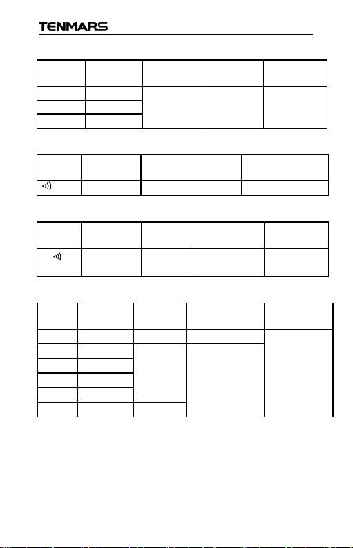
Frequency (Auto-Ranging)(12E)
Sensitivity
Protection
4KHz
1Hz
40KH
z
10Hz
400KHz
100Hz
Protection
Voltage
Protection
Sensitivity
Protection
Range Resolution Accuracy Max.
TM-12E/13E/13R
Overload
(0.8%+3)
3V rms DC/AC
600V rms
Continuity
Range Buzzer Max. Open Voltage Overload
below 40
About-1.5VDC 600V rms
Resistance (12E)
Range Resolution Accuracy Max. Open
0.1
(1%+5)
About-1.5VDC600V rms
Overload
(400)
Resistance (Auto/Manual)(13E/13R)
Range Resolution Accuracy Max.
4000.1
(1%+5)
about -1.5VDCDC/AC
4K 1
40K 10
(1%+3)
About-0.45V
Overload
600V rms
(60 Second)
DC
400K 100
4M 1K
40M 10 (3%+3)
EN-7
Page 9

TM-12E/13E/13R
3. INSTRUMENT DESCRIPTION
a. Safety guard.
b. Jaw Trigger.
c. Rotary Range Selector.
d. LCD
e. COM Jack: it is used for the connection of negative signal
input while measuring DCV, ACV,Ω/ .
f. V/Ω Jack: It is used for the connection of positive signal
input while measuring DCV,ACV,Ω/ .
g. RANGE Button: Manual ranging is allowed while the button
is pressed, and the symbol MANU is shown on LCD, The
auto ranging mode is activated again while pressing the
button more than 2 seconds or setting the range.
h. DATA HOLD button: The reading data shown on LCD can be
locked while pressing the button.
i. ZERO button: The reading data shown on LCD can
be reset to 0 while the button is pressed once, and
the symbol “ZERO” is also displayed on LCD, Press
the button again, the data cleared can be shown on
LCD, and the symbol “ZERO” begins to blink. To
abort the zero mode, hold down the button for more
than 1 second. (13E/13R)
EN-8
Page 10
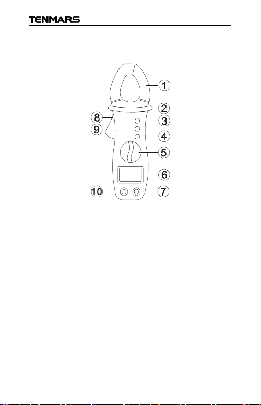
Fig.1
1. Inductive clamp Jaw
2. Safety guard
3. Data hold utton(12E)
ZERO button(13E/13R)
4. Range button(13E/13R)
5. Rotary Range selector
6. LCD
7. V/ΩJack
8. Jaw Trigger
9. Range button(12E)
Hold button(13E/13R)
10. COM Jack
TM-12E/13E/13R
EN-9
Page 11

TM-12E/13E/13R
CAUTION
4. MEASUREMENT
When this button is pressed, the range is unchanged.
4.1. NOTES
1. Check if the batteries are installed properly.
2. Check if the LCD and the range indicator show the
same as the function desired.
3. When changing range, firstly remove the tested
conductor or electrical circuit from the clamp jaw in
order to avoid and accident.
4. Strong vibrations and impacts, may cause damage
to the instrument.
5. Do not test on or connect to any circuit with voltage
or current exceeding the specified overload
protection.
6. When measuring resistor, Please do not add any
voltage, though there is a protection circuit,
excessive voltage will still cause malfunction.
7. When measuring current, firstly remove the test
leads of common and voltage / resistance.
8. When measuring current, any strong current nears
or closes to the clamp jaw will affect the accuracy.
9. This instrument is not available for the non-sine
wave AC signal, otherwise there will be a great error.
10. When measuring current, always put the tested
conductor in the center of the clamp jaw so as to
obtain a more accurate reading.
11. During measuring, if the value of reading or
indication of sign remain unchanged, check if the
DATA HOLD function is active and the symbol H is
displayed on the LCD.
EN-10
Page 12
TM-12E/13E/13R
ads are disconnected
Incorrect
Correct
12. In order to avoid reading incorrect data, you have to
replace the batteries immediately when the symbol
BAT appears on the LCD.
13. Do not touch the circuit board before you take any
adequate action, and thus prevent from any
damage of contamination and static electricity.
4.2. AC CURRENT (ACA) MEASUREMENT
WARNING
Make sure that all the test le
from the meter’s terminal forcurrent measurement.
1.Select “~A” range.
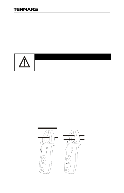
2.Open the clamp and put the tested conductor in the
center of the clamp jaws (see Fig.2).(No gap is
allowed between the connections of clamp jaws)
3.The current value will be indicated on the LCD.
4. If the reading is difficult, press the DATA HOLD
button to hold the obtained value. To exit from this
function press DATA HOLD button again.
Fig. 2
EN-11
Page 13
TM-12E/13E/13R
WARNI
NG
Maxim input for DCV or ACV is 600V. Do not attempt
to take any voltage measurement that exceeds the
limits. Exceeding the limits could cause electrical
WARNING
Maximum input for DCV or ACV is 600V. Do not
attempt to take any voltage measurement that
exceeds the limits. Exceeding the limits could cause
4.3. AC VOLTAGE (ACV) MEASUREMENT
shock and damage the clamp meter.
1.Select “V~" range.
2.Insert the test leads into the jacks. The red test lead
plug into V/Ω jack, and the black test lead plug into
COM jack.
3.Connect the two long ends of test leads to the
desired circuit, and then reading will be displayed.
4.If the reading is difficult, Press DATA HOLD button to
hold the obtained value. To exit from this function,
press DATA HOLD button again.
4.4. DC VOLTAGE (DCV) MEASUREMENT
electrical shock and damage the clamp meter.
1.Select “ V” range.
2.Insert the test leads into the jacks. The red test lead
plug into V/Ω jack and the block test lead plug into
COM jack.
3.Connect the two long ends of test leads to the
desired circuit.
4.If the reading is difficult, press DATA HOLD button to
hold the obtained value. To exit from this function,
press DATA HOLD button again.
EN-12
Page 14
TM-12E/13E/13R
WARNING
Make sure that all the test leads are disconnected
WARNING
Before taking any in circuit resistance measurement,
the circuit being tested and
discharge all the capacitors. If a reading is over
4.5. DC CURRENT (DCA) MEASUREMENT
from the meter’s terminal for current measurement.
1. Select “ A” range.
2. Check if the display shows zero in advance. If the
display doesn’t show zero, press “ZERO” button. (If
the current measurement is over 40A, press
“RANGE” button to select 400A range before zeroing.
3. Open the clamp and put the tested conductor in
the center of the clamp jaws (See Fig.2). (No gap is
allowed between the connections of clamp jaws).
4. The current value will be indication on the LCD.
5. The excesses magnetic value should be deducted
from the reading data if auto zero is not performed.
4.6. RESISTANCE MEASUREMENTS
remove power from
range, the message “OL” will be displayed.
1.Select “/ ” range.
2.Insert the test leads into the jacks, the red test lead
play into” V/” jack, and the black test lead plug into
COM jack.
3.Connect the two long ends of test leads to the
desired circuit, then reading will be displayed.
4.Press DATA HOLD button to hold the value when
takes the resistance measurement, if it’s necessary.
EN-13
Page 15
TM-12E/13E/13R
4.7. CONTINUITY TEST
1.Select “V/ “ range.
2. Insert the test leads into the jacks. The red test lead
plug into V/Ω jack, and the black test lead plug into
COM jack.
3. Connect the two long ends of test leads to the
desired circuit, then reading will be displayed while
the buzzer sounds the resistance value is lower than
40Ω approximately.
4.8. FREQUENCY MEASUREMENT
1.Select “Hz” range.
2. Insert the test leads into the jacks, the red test lead
plug into V/Ω jack, and the black test lead plug into
COM jack.
3. Connect the two long ends of test leads in parallel to
the desired circuit, then reading will be displayed.
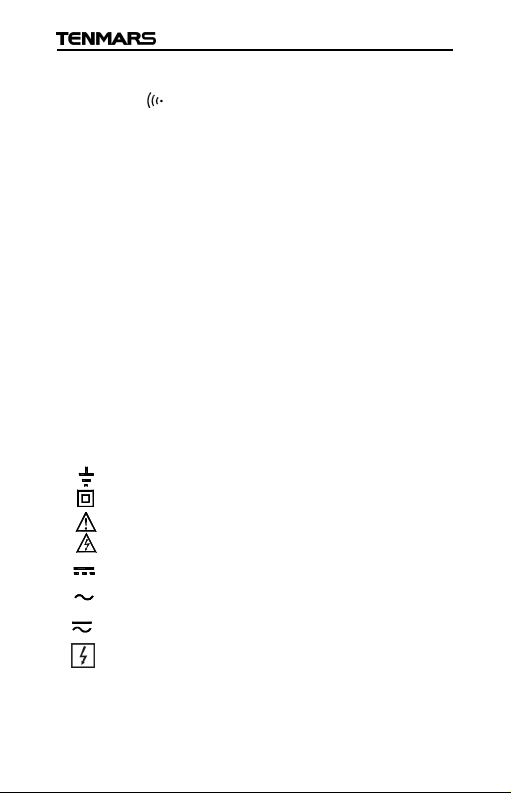
5. SYMBOLS DESCRIPTION
Ground
Meter Double insulated
Caution
Danger high voltage: risk of electric shock
DC Voltage or Current
AC Voltage or Current
DC/AC Voltage or Current
Application around and removal from hazardous
live conductors is permitted
EN-14
Page 16
TM-12E/13E/13R
CAUTION
Take extreme care for the following cond itions while
If the equipment is used in a manner not specified
by the manufacturer, the protection provided by the
equipment may be impaired.
Do not touch or be close to the inductive clamp when
measuring current.
Individual protective equipment (for example:
Insulation gloves) must be used when measuring
current.
CAT Ⅳ - Is for measurements performed at the
source of the low-voltage installation.
CAT Ⅲ - Is for measurements performed in the
building installation.
CAT Ⅱ - Is for measurements performed on circuits
directly connected to the low-voltage installation.
CAT Ⅰ- Is for measurementsperformedoncircuits
not directly connected to mains.
6. SAFETY PRECAUTION
measuring
1.Measuring voltage over 20V as it may cause human
body electricity conduction.
2.Measure AC power.
3.Do not measure voltage, current under humid or wet
environment.
4.If any unusual condition of test leads’s end (metal
part). And attachment of the meter, such as breakage,
deformation, fracture, foreign substance, No display,
etc., do not conduct any measuring.
5.Do not contact any exposed metal (conductive) parts,
such as end of test lead, jack, fixing object, circuit
etc,.
EN-15
Page 17

TM-12E/13E/13R
6.Keep you insulated from the object waiting for
measuring.
7.Do not operate the meter under the environment with
explosive gas (material), combustible gas(material)
steam or filled with dust.
8.In order to avoid reading incorrect data, you have to
replace the batteries immediately when the symbol
BAT appears on the LCD.
9.In order to avoid the damage caused by
contamination and static electricity, do not touch the
circuit board before you take any adequate action.
7. MAINTENANCE NOTES
7.1. BATTERY REPLACEMENT
1.If the symbol"BAT"is shown on the display while
measuring, you have to replace the batteries.
2.Remove all test leads and the conductor under test
before performing of battery replacement.
3.Set the range to OFF position.
4.Remove the screws from the battery cover with
screwdriver, and detach the battery cover from the
bottom cover.
5.Remove the batteries from battery holder carefully,
(replace them with new batteries UM-4 or SIZE 1.5V
x 2).
6.Attach the battery cover back to its right place, and
tight it with screws.
EN-16
Page 18
TM-12E/13E/13R
7.2. MAINTENANCE AND CARE
1.This meter is a precision digital instrument. Whether
in use or in storage, please do not exceed the
specification requirements to avoid any possible
damage or danger during use.
2.Do not use strong or abrasive detergents, water, and
wet cloth to clean the instrument. Do use a dry cloth
to clean the instrument.
3.Do not place this meter in high temperature or
humidity or expose to direct sunlight.
4.Once the measurement is completed, turn the rotary
switch to off. Remove the batteries from battery
holder if the instrument is not be used for a long
period in order to avoid the liquid leakage from the
battery.
5.That all necessary requirements of inspection and
maintenance are not mentioned in this manual, a
qualified technician should perform it.
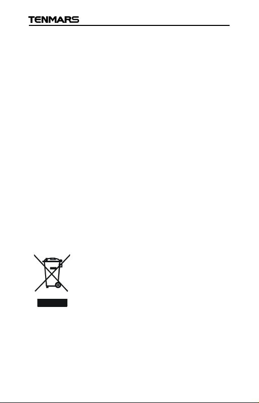
8. END OF LIFE
Caution: this symbol indicates that
equipment and its accessories shall be
subject to a separate collection and
correct disposal
EN-17
Page 19

Page 20

TENMARS ELECTRONICS CO., LTD
6F, 586, RUI GUANG ROAD, NEIHU,
TAIPEI 114, TAIWAN.
E-mail: [email protected]
http://www.tenmars.com
 Loading...