

Tendercare Snapi Pushchair, Snappi Pushchair User Manual

Snappi System User Manual
Document No: 053-05 v19 Page 1 of 66 March 2013
Snappi System User Manual.doc
Snappi Pushchair
U
SER
M
ANUAL
This manual covers:
Size 1 and 2 Snappi Pushchair
IMPORTANT
Please read these instructions carefully
Before using the Snappi System
Snappi System User Manual
Document No: 053-05 v19 Page 2 of 66 March 2013
Snappi System User Manual.doc
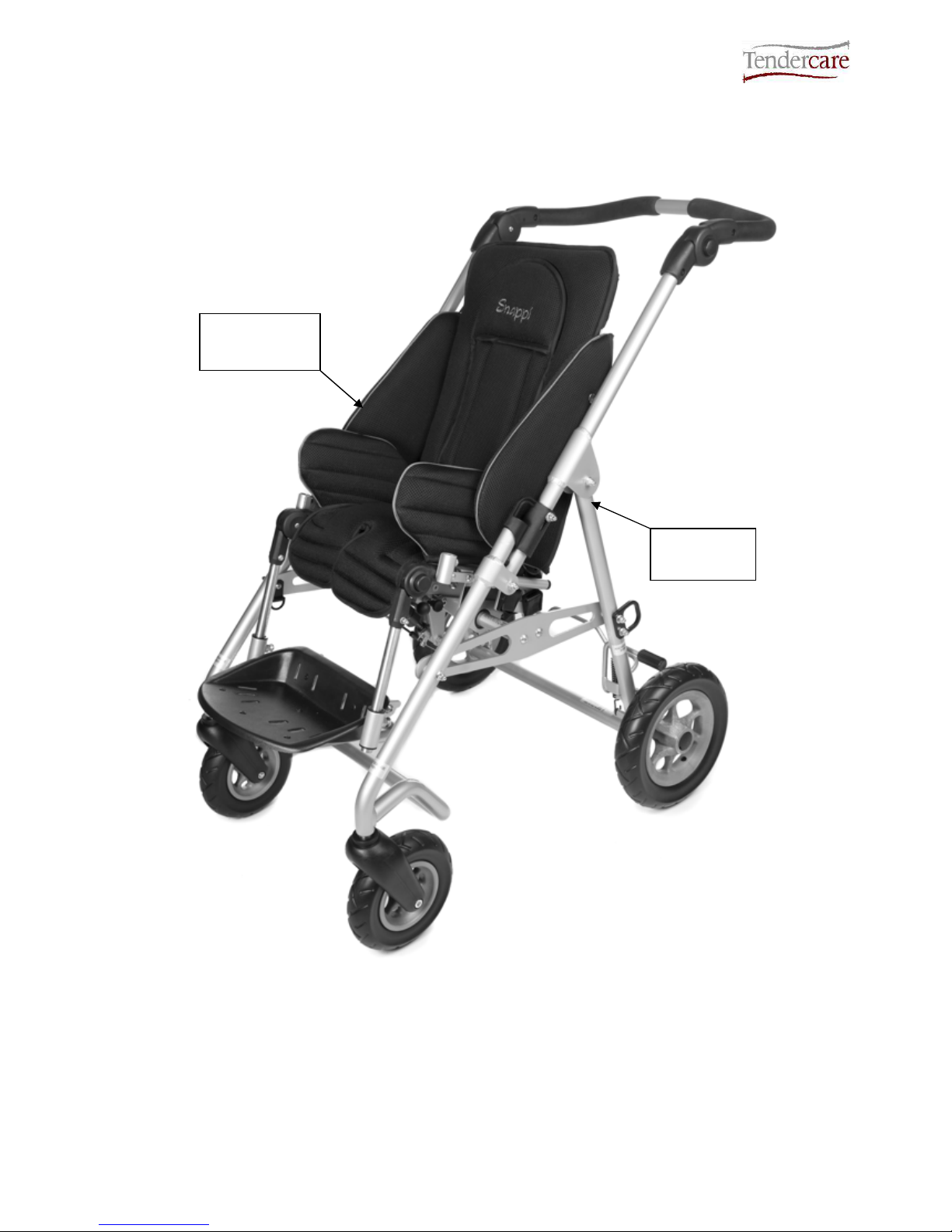
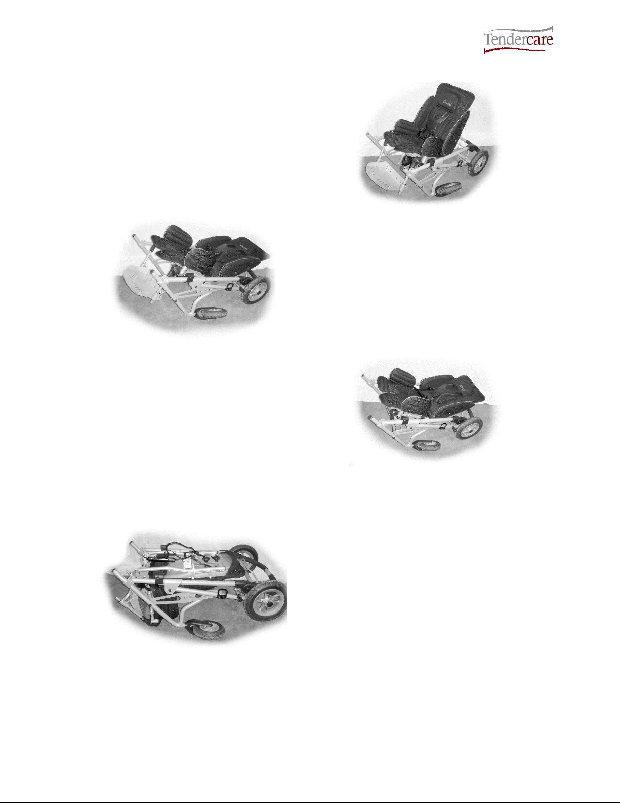
Fig 0.1 Complete Pushchair (size 1 shown)
Snappi
Seat Unit
Snappi
Chassis
Snappi System User Manual
Document No: 053-05 v19 Page 3 of 66 March 2013
Snappi System User Manual.doc
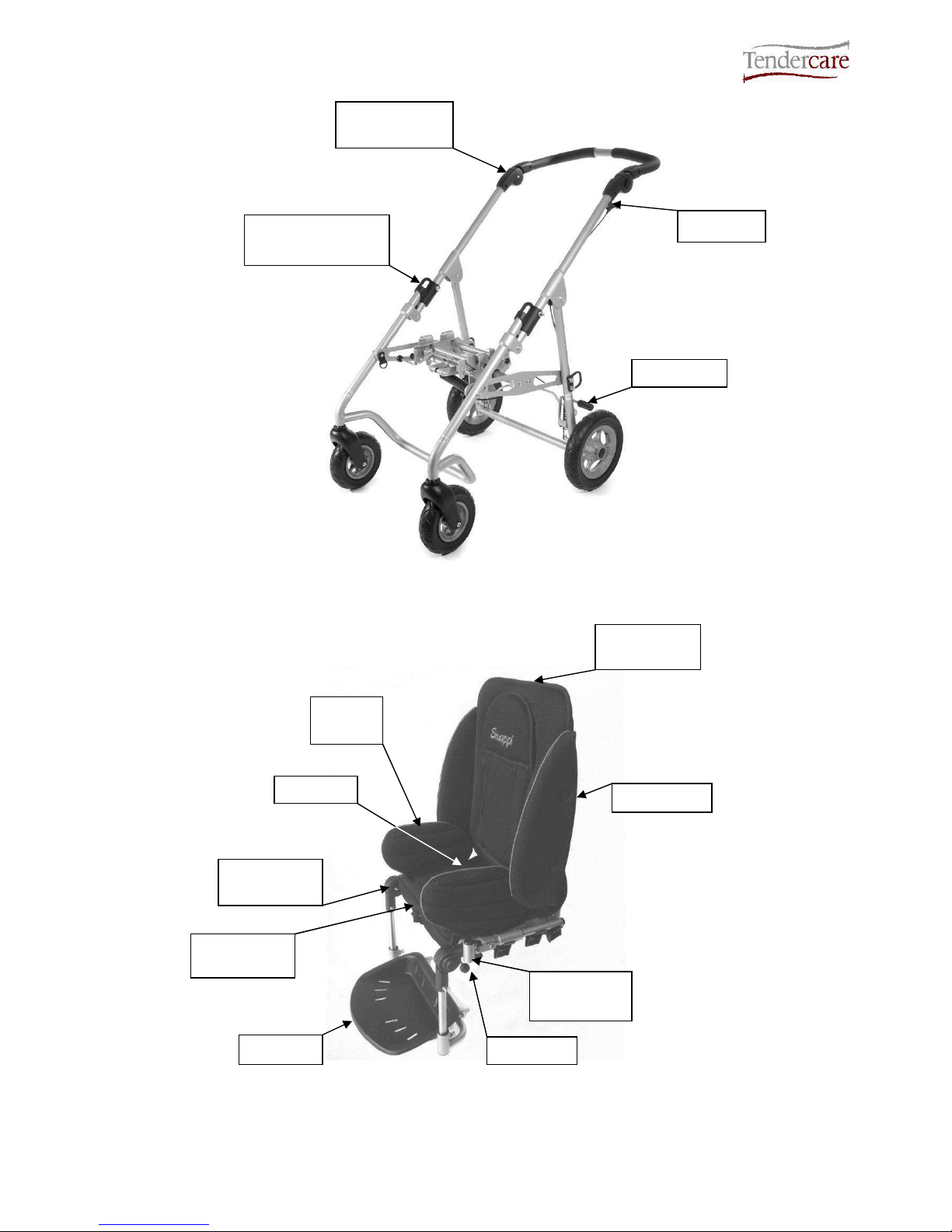
Fig 0.2 Chassis (size 1 shown)
Fig 0.3 Seat Unit (Size 1 shown)
Brake Bar
Push Handle
Adjustor
Tilt Lever
Spring Loaded
Locking Slider
Adjustable
Back
Hip
Guides
Side Pads
Interface
Playtray
Mountings
Footrest
Adjustable
Base
Knee Angle
Adjustors
Hip Belt
Snappi System User Manual
Document No: 053-05 v19 Page 4 of 66 March 2013
Snappi System User Manual.doc
Fig 0.4 Folded System - Complete (size 1 only)
Fig 0.5 Folded System - 2 part fold (all models)

Snappi System User Manual
Document No: 053-05 v19 Page 5 of 66 March 2013
Snappi System User Manual.doc
Item
Description
Page
1 Who to contact if you have difficulty 7
2 Introduction 7 - 9
3 Unpacking 9 - 10
4 Preparing the wheelbase for use 10 - 18
4.1.1 Unfolding the Frame (Original Locks) 11 - 12
4.1.2 Unfolding the Frame (Spring Loaded Locks) 12 - 13
4.2 Brakes 13
4.3 Fitting the seat to the chassis 14 - 16
4.4 Using the Tilt In Space facility 17
4.5 Folding as a complete system (size 1 only) 18
4.6 Folding as a 2 part system (all models) 18
5 Setting up the seat unit 19 - 33
5.1 Adjusting the seat unit 20
5.1.1 Seat Depth and Hip Guides 21
5.1.2 Footrest Depth and Knee Angle Adjustment 22
5.1.3 Back height and recline angle adjustment 23
5.1.4 Lateral Supports (Optional) 24 - 25
5.2 Fitting and removing the cover 25 - 26
5.3 Fitting a Headrest Pad or Lateral Head Supports (optional) 26 - 27
5.4 Fitting the Pelvic Strap 28 – 29
5.5 Fitting a Groin Adaptation Strap 30
5.6 Fitting a Butterfly/Chest Harness 31 - 34
6 Accessories 35 - 48
6.1 Shopping Basket 35
6.2 Equipment Carrying Tray 36
6.3 Sun Canopy 37 – 38
6.4 Sun Hood and Transparent Rain Shield 39 - 42
6.4b New Style Sun Canopy Fixings 43 – 45
6.4c Removing the Cover For Washing 45 – 47
6.5 Rain Cover 48
6.6 Frame Padding 49
6.7 Grip Rail 49
6.8 Playtray 50 – 52
6.9 Pommel 52 – 53
6.10 Ramped Seat Pad 53 – 54
6.11 Foot Muff 54 – 56

Snappi System User Manual
Document No: 053-05 v19 Page 6 of 66 March 2013
Snappi System User Manual.doc
7 User Instructions 56
7.1 Getting into the Snappi Pushchair 56
7.2 Getting out of the Snappi Pushchair 56
8 Attendant pushing 56
8.1 Pushing 56-57
8.2 Brakes 57
8.3 Comfort 57 – 58
8.4 Lifting and general safety 58
9 Cleaning 58
9.1 Buggy and seat unit 58
9.2 Seat Cover 58
9.3 Pelvic strap & harnessing 58
10 Maintenance 59
10.1 Routine maintenance 59
10.2 Six-monthly maintenance 59 – 60
11 Oxygen Cylinder 60
12 Warranty 60 – 61
13 Transporting the Wheelbase 61
13.1 Preparing the system for transport 61 – 63
13.2 Attaching wheelbase to vehicle 63 – 65
14 Repairs 66

Snappi System User Manual
Document No: 053-05 v19 Page 7 of 66 March 2013
Snappi System User Manual.doc
1: Who to contact in difficulty
Tendercare Ltd.
PO BOX 3091, Littlehampton, BN16 2WF
Tel: (01903) 726161 Fax: (01903) 734083
Email: info@tendercareltd.com
Web: www.tendercareltd.com
2: Introduction
The Snappi is a highly adjustable pushchair designed to accommodate a wide variety of
special seating needs. The pushchair system comprises a wheelbase and a seating unit,
which is easily removable for storage and transport thanks to its integrated interface. The
system is available in 2 sizes.
The Wheelbase is made of a strong and lightweight aluminium alloy, minimising weight
and providing a very rugged frame. The wheelbase provides a tilt in space facility and has
2 fixed rear wheels and 2 castor wheels at the front for easy steering.
The Seat unit offers best in class growth, thanks to its versatile design and large ranges of
adjustments to all supports. It has an easy to remove, breathable cover, and comes
supplied with a hip belt as standard.
Seat adjustments (please see table below for details of adjustment ranges): Seat depth
adjustment, depth and length adjustable Hip Guides, Back Height adjustment,
Independent back recline (using an easy to operate gas strut mechanism) and depth &
angle adjustable Footrest. The seat also includes an interface allowing it to be quickly
fitted and removed from the wheelbase, and like the entire Snappi range, includes all the
latest safety mechanisms (including an innovative 2 stage release to prevent little fingers
causing accidents).
The following accessories for use with the Snappi Pushchair are available from
Tendercare Ltd.
Wheelbase Accessories: Equipment carrying tray, Shopping basket, and Rain-hood.
Seat Accessories: Height and width adjustable wrap around Lateral Supports, Butterfly
chest harness, Foot and Toe Straps, Pommel, Play Tray, Lateral Head Supports, Standard
Headrest, Extra recess Headrest, and Occipital roll Headrest.
These instructions apply to all sizes.
A child’s safety is your responsibility. As such we recommend that you read the
complete user manual prior to using your pushchair.
Snappi System User Manual
Document No: 053-05 v19 Page 8 of 66 March 2013
Snappi System User Manual.doc
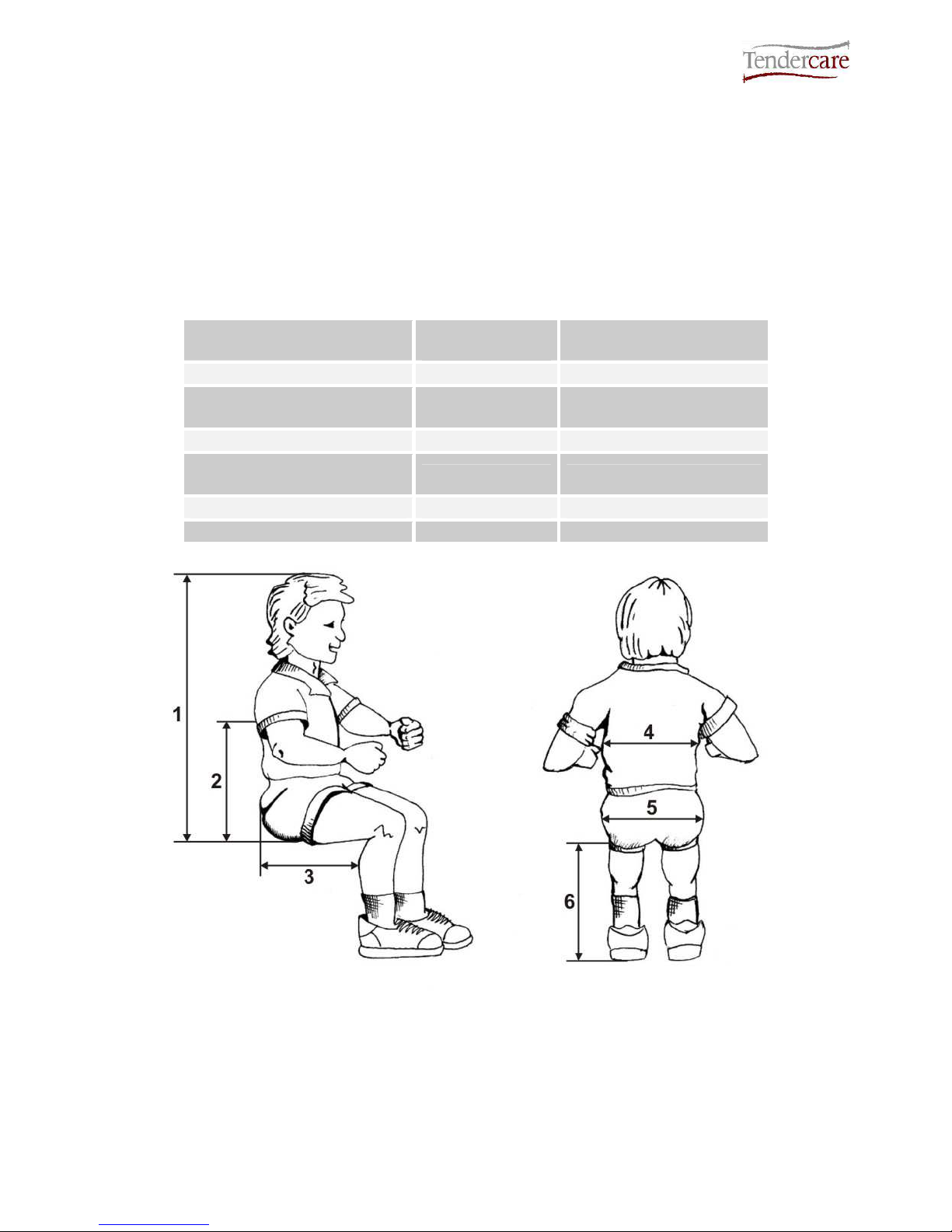
Snappi Seat Adjustments
Support
Snappi Pushchair Size 1
Snappi Pushchair Size 2
Seat Depth 195-295mm 290-390mm
Seat Width 190-290mm 250-350mm
Backrest Height 450-620mm 540-700mm
Footrest Depth 150-280mm 215-360mm
Back Recline Angle 90°- 135° 90°- 135°
Knee Angle* -15°- 90° -15°- 90°
Total System Weight 19Kg 22Kg
Maximum Carry Weight 35Kg 40Kg
IMPORTANT:
* Knee angle adjustable in 15° increments
** Maximum carry weight includes the occupant and all accessories.
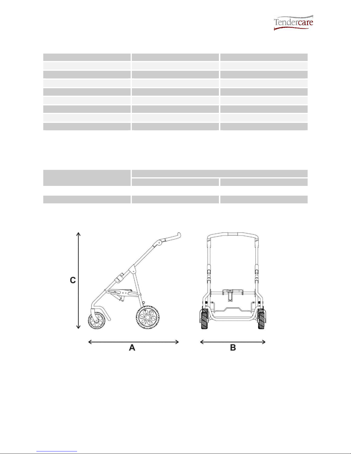
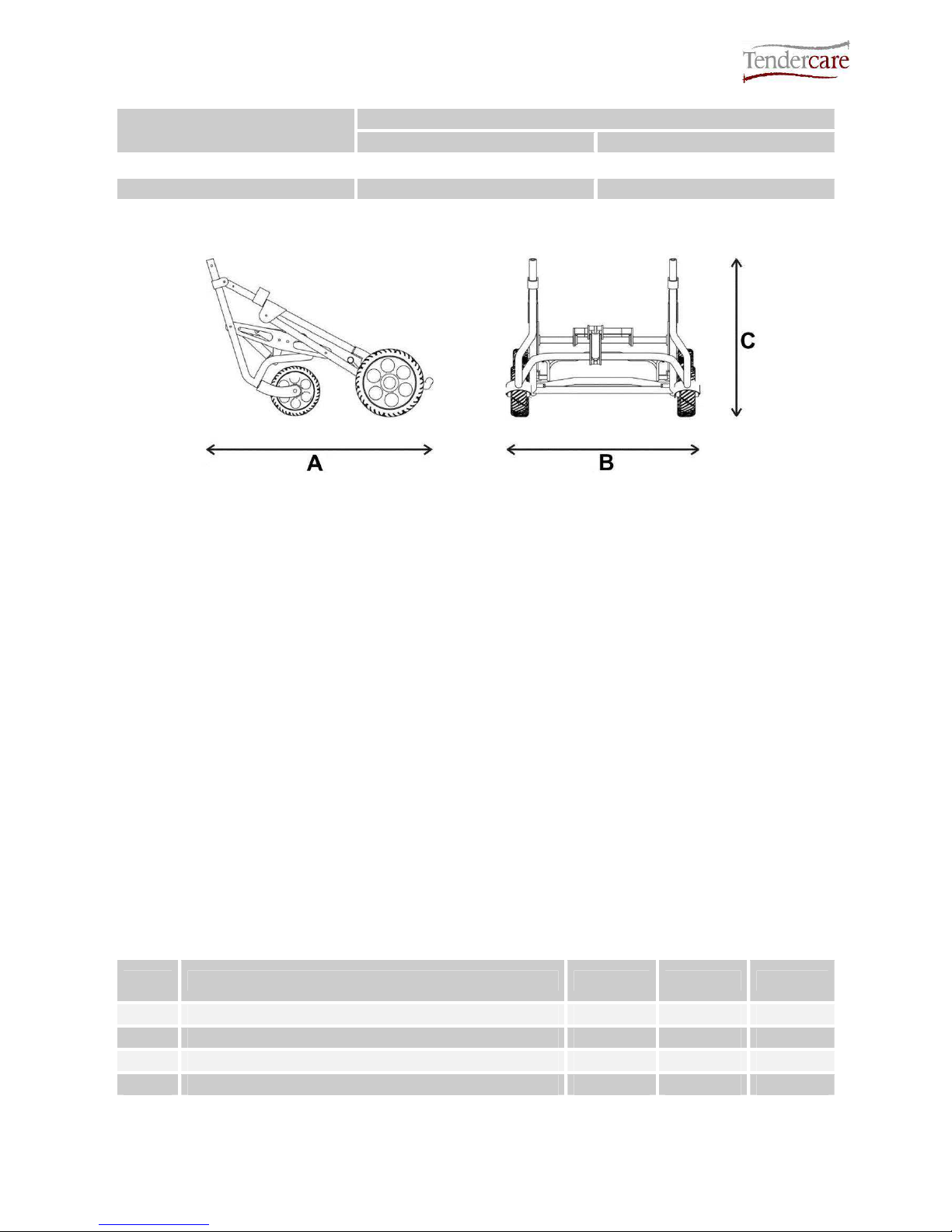
Dimensions (mm)
Snappi Pushchair (Open)
Size 1 Size 2
A 944 960
B 571 684
C 992 998
Snappi System User Manual
Document No: 053-05 v19 Page 9 of 66 March 2013
Snappi System User Manual.doc
Dimensions (mm)
Snappi Wheelbase Folded
Size 1 Size 2
A 771 798
B 571 684
C 573 560
Please note sizes for complete pushchair are not given, as overall size of pushchair is
dependant on the specific settings of the seat.
All sizes and weights are given as a guide. Tendercare ltd reserves the right to amend
specifications at any time as part of their product development programme.
3: Unpacking
The wheelbases and seat unit are delivered together in a cardboard carton. This measures
680mm wide x 480mm deep x 1030mm high and weighs approximately 18Kg (size 1) or
20Kg (size 2).
WARNING:
The transit carton is quite bulky so moving and unpacking must be done with care.
Observe all lifting and handling regulations.
Stand the carton upright making sure it is supported and cannot fall over. Open the carton
and remove any packages or packing, which could obstruct the removal of the seat and
wheelbase. Remove the seat first, then the wheelbase. Do not attempt to lift both parts out
together.
The carton should contain the following items:
Item Component QTY. Yes No
1 Size 1 or 2 Wheelbase 1
2 Size 1 or 2 Seat Unit 1
3 User Manual 1
4 5mm Alan key 1

Snappi System User Manual
Document No: 053-05 v19 Page 10 of 66 March 2013
Snappi System User Manual.doc
The following items should be fitted to the seat as standard:
Item
Component
QTY.
Yes
No
5 Hip guide covers 2
6 Seat Base Cover 1
7 Seat Back Cover 1
8 Side Pads 2
9 Hip Belt 1
Please note, accessories such as lateral supports or harnessing that were ordered at the
same time as the pushchair will be included in the main package.
Larger accessories will be packaged in separate cartons (e.g. the rain cover).
IMPORTANT:
If any items are damaged or missing, then please contact Tendercare, preferably by email at
info@tendercareltd.com or alternatively please call us on (01903) 726161 within 36 hours of
delivery.
After unpacking and checking you have all components and they are in good condition
dispose of the packaging at your local recycling centre. Alternatively retain and reuse.
4: Preparing the wheelbase for use
WARNING:
When opening or folding the wheelbase, ensure that you hold the frame so that you
avoid any danger of catching your fingers in moving parts.
Keep children clear of the wheelbase during opening and folding.
Snappi System User Manual
Document No: 053-05 v19 Page 11 of 66 March 2013
Snappi System User Manual.doc
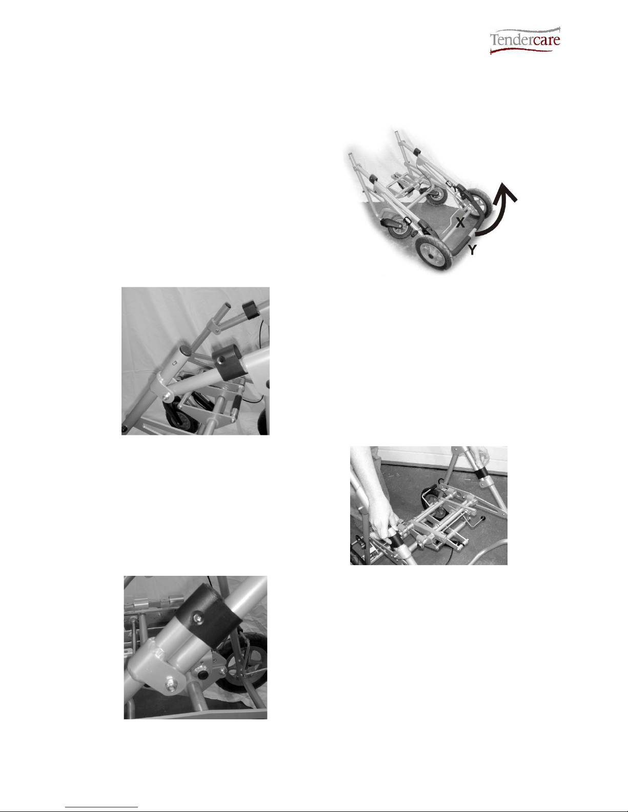
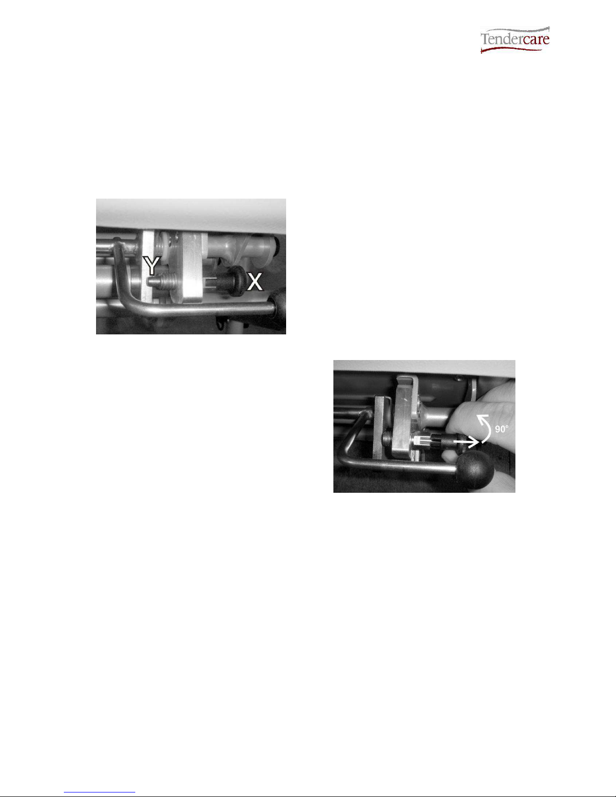
4.1.1 Unfolding the Frame (original locks)
Standing at back of the wheelbase,
place your foot on the rear cross
member X (see Fig 4.1.1.1) and lift
handle labelled Y as far as it will move.
This will open the frame.
Fig 4.1.1.1
Fig 4.1.1.2
Next locate the 2 plastic locking sliders (See
Fig 4.1.1.2). These will be stowed in the
“open” position and are held in place by 2
small spring clips.
Press the 2 silver “Spring pins” in and
slide the 2 locking pieces down over the
lower tube sections. (See Fig 4.1.1.3)
Fig 4.1.1.3
Fig 4.1.1.4
The pins will spring through the holes in the
sliders and hold them in place (see Fig
4.1.1.4).
Snappi System User Manual
Document No: 053-05 v19 Page 12 of 66 March 2013
Snappi System User Manual.doc
WARNING:
If the locking sliders are not in the correct position, or the spring pins do not
protrude thereby allowing the locking clips to move back up the frame, then the
frame may collapse in use.
Folding the wheelbase: To unlock the frame and fold the wheelbase, reverse the above
instructions.
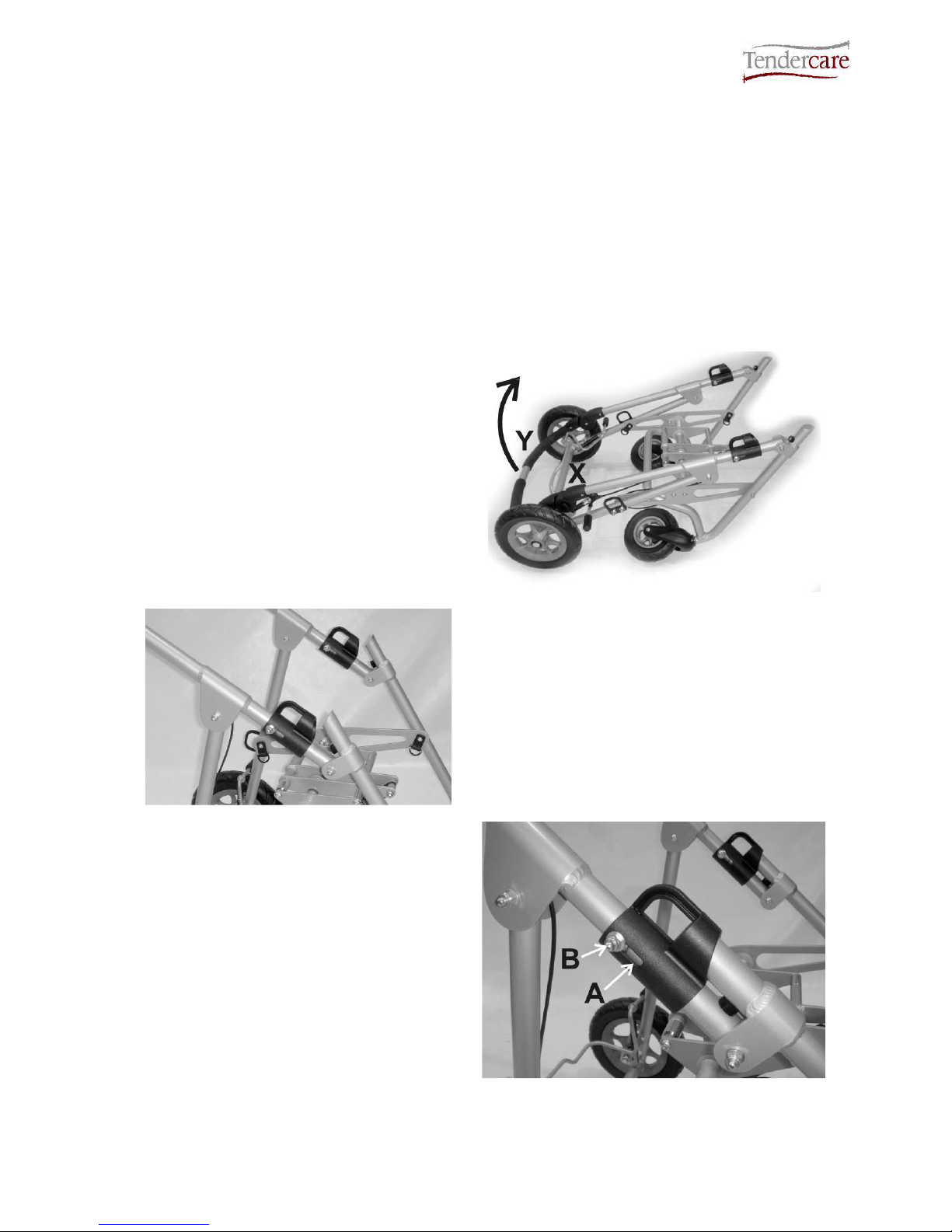
4.1.2 Unfolding the Frame (Spring loaded locks)
Standing at back of the wheelbase, place
your foot on the rear cross member X
(see Fig 4.1.2.1) and lift handle labelled
Y as far as it will move.
This will open the frame.
Fig 4.1.2.1
Fig 4.1.2.2
Once the frame is almost open, the 2 plastic
frame locks will engage with the angled
sections of the lower frame.
Continue to unfold the frame; this will force
the locks up the tubes. There will be some
resistance, as you will be working against the
locking springs.
Once fully open, the frame locks will snap
shut over the front frame, securing the
frame in the open position.
Always check that both locks are fully
closed. In the locked position the guide
bolt ‘B’ will be sat in the top of the slot ‘A’
on the side of the slider as shown (see
Fig 4.1.2.3). If there is any slot visible
above the guide bolt, push the lock down
by hand until it will not move any further.
Fig 4.1.2.3
Snappi System User Manual
Document No: 053-05 v19 Page 13 of 66 March 2013
Snappi System User Manual.doc
Fig 4.1.2.4
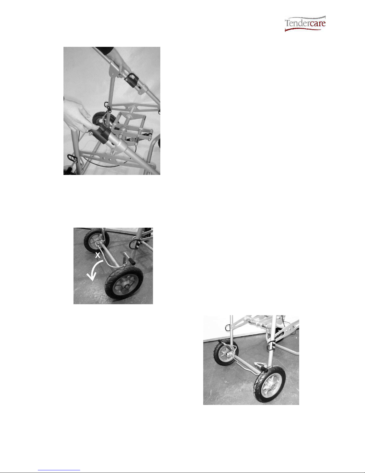
To fold the frame:
Standing beside the frame, pull up the 2
locking sliders as shown (see Fig 4.1.2.4).
Whilst holding the locks open, push down
with your arm on the upper frame or push
handle, so that the frame starts to fold.
Release the locking sliders, and fold down
the frame by moving the push handle down
as far as it will move.
IMPORTANT:
Always check that BOTH frame locks are fully closed before using the frame. If they
are not properly engaged, the frame could collapse during use.
4.2 Brakes
Fig 4.2.1
To apply the brake, put your foot on the top
of brake bar (labelled X) and push down as
shown. The brake will flip down onto the
wheels and lock them.
To release the brake, hook your foot
between the middle raised portion of the
brake bar, and the frame cross bar. Then,
lift the brake bar with your foot until it flips
back and stops against the brake stop pins.
Please note you may find it easier to use
your hand to release the brake.
Important:
Always put the brake on when placing the
child in, or taking them out of the pushchair.
Do not leave the brake on when the
pushchair is not in use as this will damage
the rear wheels.
Fig 4.2.2
WARNING:
The brake mechanism is spring loaded so care must be taken when operating it.
Snappi System User Manual
Document No: 053-05 v19 Page 14 of 66 March 2013
Snappi System User Manual.doc
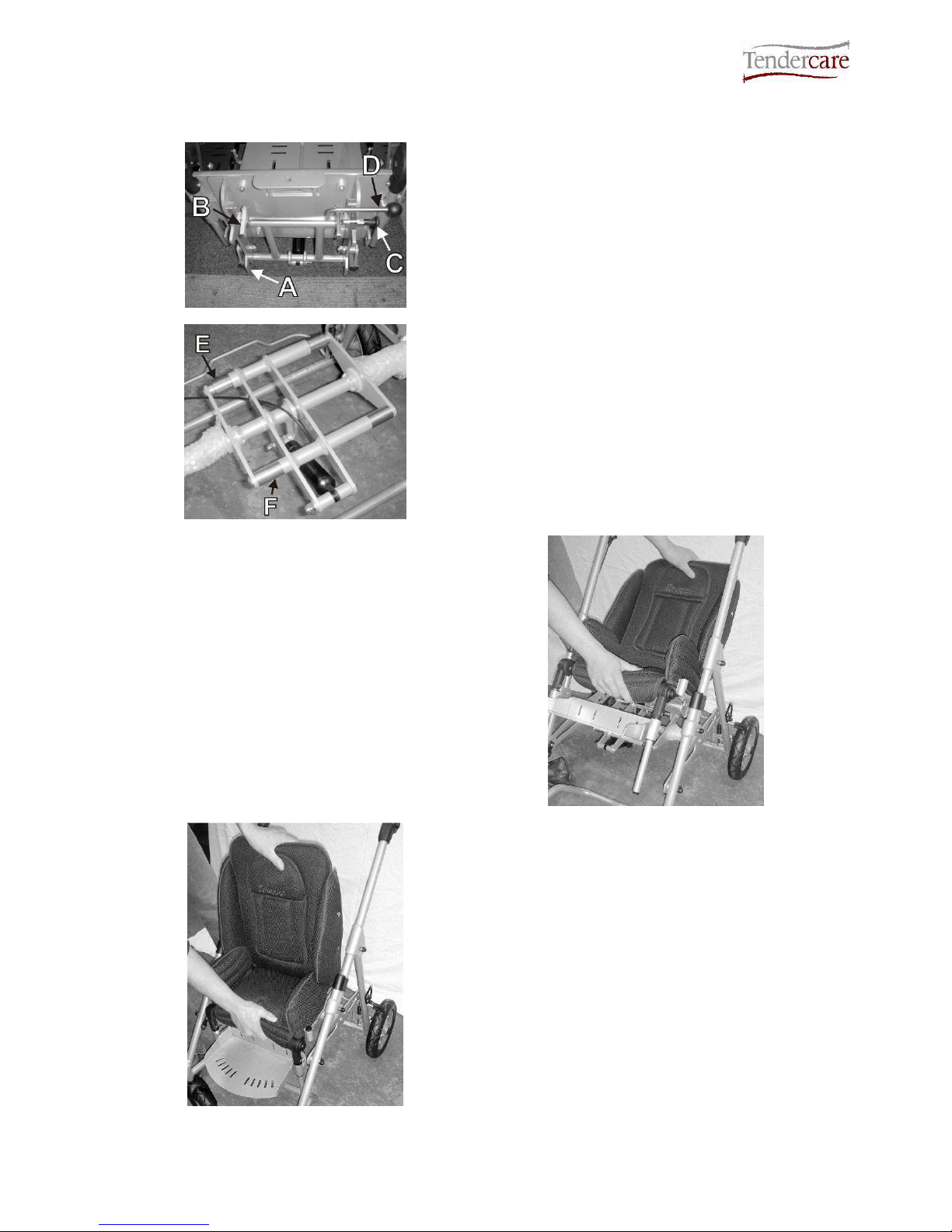
4.3 Fitting the seat to the chassis
The seat incorporates an Interface system, and includes a 2-stage latch that comprises a
main latch and a second safety latch that prevents accidental release of the seat from the
chassis.
The safety catch must be correctly set before the main catch can be operated:
How to operate the safety catch:
Fig 4.3.1
Safety Catch Locked
The safety catch clip is located under the
front right corner of the seat near to the
release lever.
Definition of components:
X: Pull handle
Y: Locking Pin
To release it, pull the handle “X”, and turn it
90 degrees so that the pin “Y” is fully
retracted.
To lock it, pull “X” and turn 90 degrees in
the opposite direction, so that pin “Y” is fully
protruded and sits behind the interface main
catch “B” (see fig 4.3.3 on next page).
Fig 4.3.2
Safety Catch unlocked
Important:
When fitting or removing the seat, the carer / parent must first ensure that the safety
catch pin is set in the “unlocked” position. It will not be possible to fit or remove the
seat if the latch is “locked”, and attempting to do so may cause damage to the
chassis or the seat.
Once the seat has been fitted, the carer / parent must always lock the safety catch.
Note:
A warning label is positioned on the front right hand portion of the tilt frame on the
chassis, to remind carers to lock the safety catch.
Snappi System User Manual
Document No: 053-05 v19 Page 15 of 66 March 2013
Snappi System User Manual.doc
To fit the seat to the frame:
Fig 4.3.3
Fig 4.3.4
Definition of interface mounting points:
A: Seat Interface Rear Hooks
B: Seat Interface Main Clips
C: Seat Interface Safety Catch
D: Seat Interface Release Handle
E: Frame interface rear bushings
F: Frame interface front bushings
Ensure that the safety catch “C” has been
unlocked (see instructions on previous
page).
Holding the seat as shown, tilt it back and
locate the 2 rear hooks “A” on the back of
the interface, over the stainless steel
bushings on the back of the frame interface
“E”.
Fig 4.3.5
Fig 4.3.6
Next, rotate the seat forward and down so
that the main clips “B” snap over the front
stainless steel bushes on the frame
interface “F”.
Note that due to the design of the frame
interface, it is not possible to fit the seat
backwards. If fitted the wrong way around
the clips will not close and it will not sit down
into the frame.
Snappi System User Manual
Document No: 053-05 v19 Page 16 of 66 March 2013
Snappi System User Manual.doc
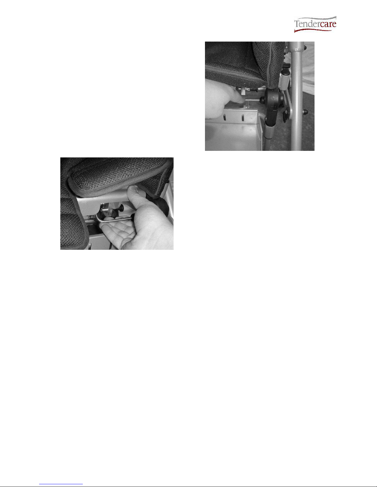
Next, push down firmly on the release lever
“D” to ensure that the clips are fully closed.
Note the lever is positioned under the front
right corner of the seat (see Fig 4.3.7).
Set the safety catch “C” to the “Locked”
position (so that the pin sits behind the
interface clip).
Fig 4.3.7
Fig 4.3.8
To remove the seat, first unlock the safety
catch “C” as detailed above.
Lift the release lever “D” up, whilst holding
the top of the seat with your other hand.
This will open the main clips “B”. Rotate the
seat back so that the main clips are clear
from the frame, and lift the seat away from
the buggy.
IMPORTANT:
Always ensure that the seat interface clips are fully closed. To test this, press down on the
release lever when fitted and make sure the clips will not move (see fig 4.3.5).
Always lock the safety catch before using the buggy.
Always unlock the safety catch before fitting or removing the seat. Attempting to fit or
remove the seat with the catch locked could cause damage to the seat or the chassis.
Do not attempt to fit the seat backwards. It will not lock in a rearward facing position.
The seat interface system is spring loaded, so ensure your fingers are clear of the clips when
fitting or removing.
Snappi System User Manual
Document No: 053-05 v19 Page 17 of 66 March 2013
Snappi System User Manual.doc
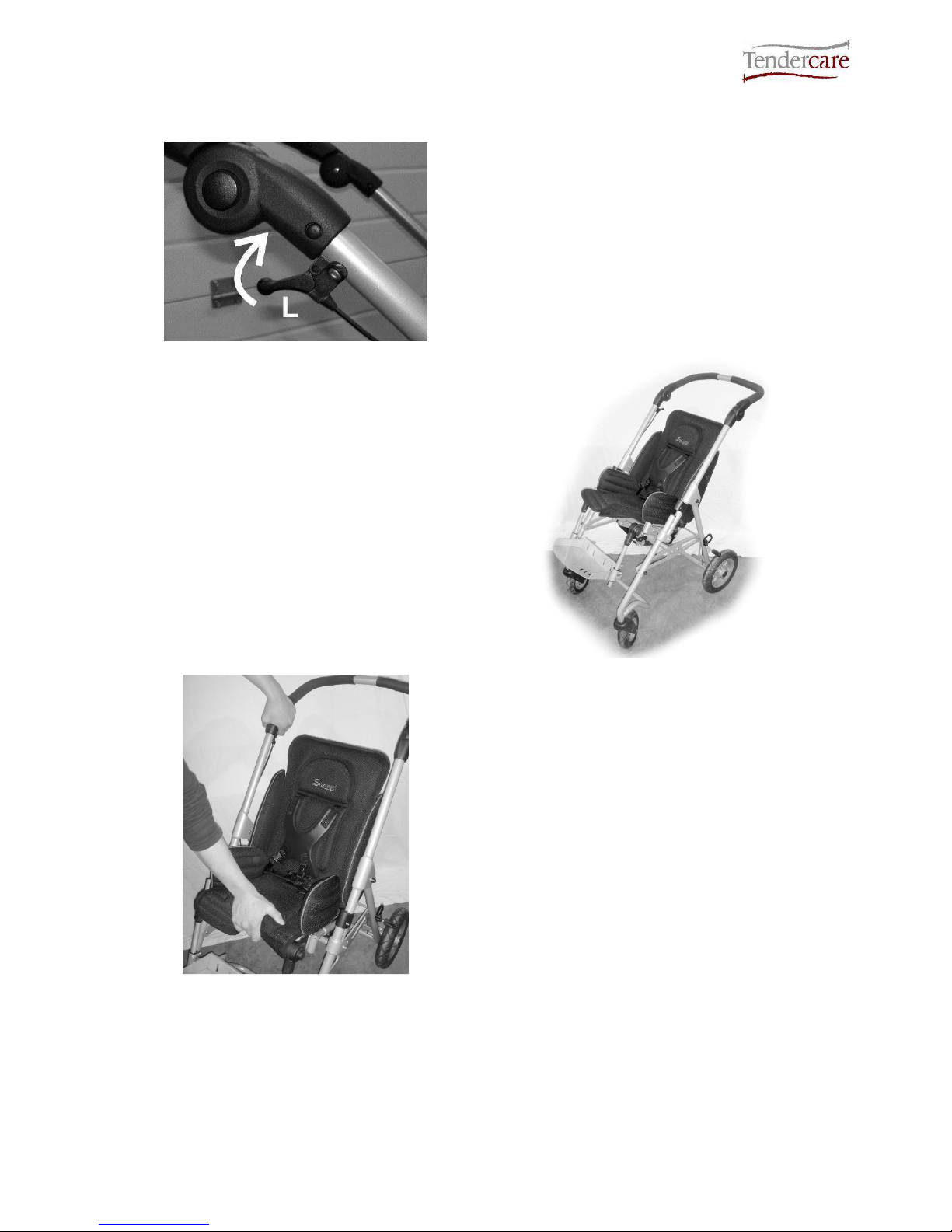
4.4 Using the Tilt in Space facility
Fig 4.4.1
To operate the tilt in space mechanism,
place your hand over the push handle
adjustor, and lift the lever ‘L’ (see Fig 4.4.1)
as shown.
This will open the gas strut and tilt the seat.
Note; The speed of tilt can be controlled by
varying the pressure applied at lever L.
Use your other hand to support seat as it
tilts.
Fig 4.4.2
Fig 4.4.3
To reset the tilt mechanism, hold down lever
L and push down firmly on the front of the
seat as shown (see Fig 4.4.3). Once in the
desired position, release lever L. For a 90degree position, move the seat so the gas
strut is fully closed and it will not move any
further before releasing the tilt lever.
IMPORTANT:
Always ensure any harness provided for the child is used and correctly adjusted before
reclining or returning the seat to a more upright position.
Always support the seat when tilting, as the gas springs can be quick to operate. If the seat is
not supported, is may move swiftly and could cause the occupant distress.
Snappi System User Manual
Document No: 053-05 v19 Page 18 of 66 March 2013
Snappi System User Manual.doc
4.5 Folding as a complete system (size 1 only) –
Not suitable for rearward facing model
First, set the seat to full tilt in space as
detailed in section 4.4
Next fold the chassis as described in
section 4.1 without removing the seat.
Fig 4.5.1
Fig 4.5.2
Next, set the seat back angle to its
maximum position as shown (see instruction
on section 5.1.3).
Finally, fold the footrest, and tuck it in using
the knee angle adjustors as shown (see
section 5.1.2 for details).
Fig 4.5.3
4.6 Folding as a 2 part system (all models) – Including rearward facing model
Fig 4.6.1
To fold the system as a 2 part, first set the
seat back angle to 90o (see section 5.1.3),
remove the seat and fold the frame as
detailed in section 4.1.
Next place the seat, face down over the
folded chassis as shown.
Finally, fold the footrest tray and angle the
footrest tubes to sit closer to the seat (see
section 5.1.2 for how to adjust and fold the
footrest).
Snappi System User Manual
Document No: 053-05 v19 Page 19 of 66 March 2013
Snappi System User Manual.doc
5.0 Setting up the seat unit
When setting up the seat unit always ensure the following is done:
• Always consult your Therapist or Rehabilitation Engineer for advice.
• Ensure that the child is relaxed and happy and if possible in an environment in
which they are familiar.
• If possible, sit the child on a plinth to take the measurements listed below:
Fig 5.0.1 Definition of measurements
Note: you can now adjust the seat to suit your child’s dimensions
Measurement
Number
(see fig 5.0.1)
Millimetres
Top of head to seat 1
Under armpit to seat
(Axilla height)
2
Actual sitting depth 3
Chest Width
(Arm pit to arm pit)
4
Hip width 5
Leg drop 6
Snappi System User Manual
Document No: 053-05 v19 Page 20 of 66 March 2013
Snappi System User Manual.doc
5.1 Adjusting the seat unit
Common adjustments on the Snappi Seat can be made by hand (such as back height and
back recline angle) and require no tools. Less frequent adjustments are made using a
5mm hexagon key (supplied), such as the seat depth and width. No other tools are
required to make adjustments to the seat.
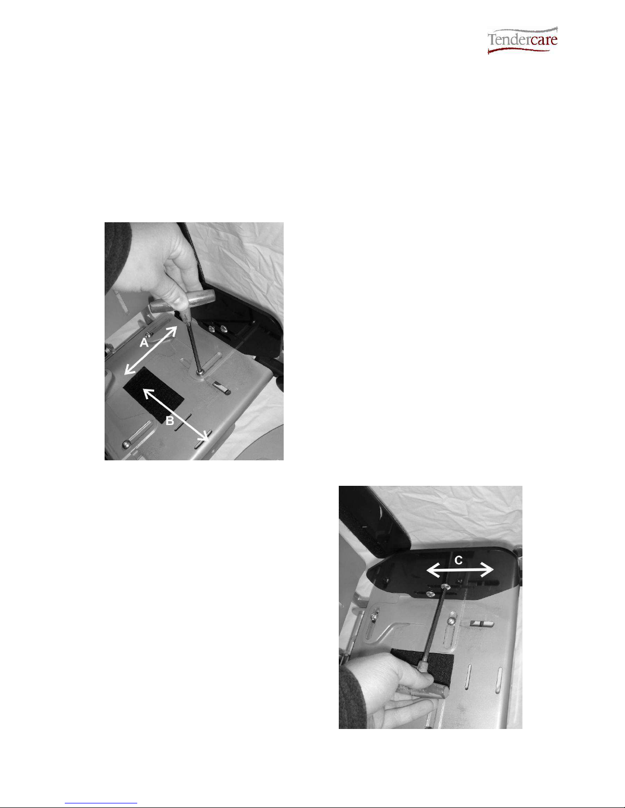
5.1.1 Seat Depth and Hip Guides
Fig 5.1.1.1
To adjust the seat depth and width, first
remove the seat base cover (this is attached
by Velcro in the centre of the seat and is
easily removed by pulling it away from the
frame).
Using the supplied 5mm hexagon key,
loosen the 4 seat fixings.
Next set the seat width (‘A’ see Fig 5.1.1.1)
as measured in section 5.0 by sliding the
hip guide brackets in or out as required.
To adjust the seat depth (‘B’ see Fig
5.1.1.1), slide the upper of the base plates
forward or back to achieve the required
position.
Once adjusted, tighten the 4 bolts using the
hexagon key and fit the cover back into
place.
The Snappi hip guide also offers depth
adjustment (‘C’ see Fig 5.1.1.2) to best suit
your child’s needs.
To adjust this, remove the hip guide cover.
This is done by unclipping the two “poppers”
and lifting the cover off the plastic plate.
Next, use the 5mm hexagon key to loosen
the 2 fixings, and slide the plate into the
desired position as shown (see Fig 5.1.1.2).
Once adjusted, tighten the 2 fixings and refit
the hip guide cover.
Fig 5.1.1.2
 Loading...