

Page 1

Step 5: Here you can configure the NAT. If you are not an advanced user, the default settings are recommended and then
click Next.
Step 6: To configure the Default Gateway interface when using IPv6, select the interface that you want to configure with
the WAN gateway address in Selected WAN Interface box. Then click Next.
Step 7: To configure the WAN DNS address, check the Obtain IPv6 DNS info from a WAN interface option, or select
the Use the following Static IPv6 DNS address option to enter the static DNS server IPv6 addresses provided by your
ISP. At last, click Next.
76
Page 2

Step 8: Here you can view your configurations. Click Apply/Save to save your settings if everything is correctly set.
When the IPoE connection is successful, you can access the Internet.
Bridging
If you wish to initiate a dialup directly from your PC for Internet access or enjoy the entire Internet connection (instead
of sharing it with others), you can select the Bridging and create a dialup program from your PC.
Step 1: Click Advanced Setup > WAN Service and then click the Add button.
Step 2: Select the ETH interface you added just now from the pull-down menu in the figure below. Click Next.
Step 3: Select Bridging. Edit the Enter Service Description. This field is optional. It is recommended that you keep the
77
Page 3

default. And click Next.
Step 4: Here you can view your configurations. Click Apply/Save to save your settings if everything is correctly set.
After the bridging connection is successful, initiate a dialup directly from your PC for Internet access.
78
Page 4

4.2.3 LAN Setup
Here you can configure the LAN IP Address and subnet mask. This IP address is to be used to access the device’s
settings through a web browser. Be sure to make a note of any changes you apply to this page.
This part includes the following information:
IPv4
IPv6 Autoconfig
IPv4
IP Address: The device's LAN IP address. The default setting is 192.168.1.1.
Subnet Mask: The LAN subnet mask of the device. Combined with the IP address, the IP Subnet Mask allows a device
to know which other addresses are local to it, and which must be reached through a gateway or modem router. You can
change the subnet mask to fit your network.
Enable IGMP Snooping: Check to enable the IGMP Snooping. It is recommended to keep the default settings.
Disable DHCP Server: Click to disable the DHCP Server.
Enable DHCP Server: Click to enable the DHCP Server.
Start IP Address: Specify the start of the range for the pool of IP addresses in the same subnet as the router.
End IP Address: Specify the end of the range for the pool of IP addresses in the same subnet as the router.
79
Page 5

Leased Time: The lease time is a time length that the IP address is assigned to each device before it is refreshed.
Static IP Lease List: Displays a list of devices with reserved static IP addresses.
Add Entries: Click to add a static IP lease entry. A maximum 32 entries can be configured.
Remove Entries: Click to remove a static IP lease entry.
Configure the second IP Address and Subnet Mask for LAN interface: If you want to configure two IP addresses for
the LAN interface, you can check this option and enter the second IP Address and Subnet Mask manually.
Apply/Save: After you configure all the needed settings, click this button to apply and save them.
_________________________________________________________________________________________________
TIP
DHCP (Dynamic Host Configuration Protocol) assigns an IP address to each device on the LAN/private network. When
you enable the DHCP Server, the DHCP Server will automatically allocate an unused IP address from the IP address pool
specified in this screen to the requesting device as long as the device is set to "Obtain an IP Address Automatically". By
default, DHCP is enabled.
IPv6 Autoconfig
Static LAN IPv6 Address Configuration
Interface Address (prefix length is required): Enter the interface address.
_________________________________________________________________________________________________
NOTE
1. IPv6 address can only be Aggregatable Global Unicast Addresses and Unique Local Address. Link-Local Unicast
Addresses and Multicast Addresses are not permitted.
2. The IPv6 address must be entered with a prefix length.
_________________________________________________________________________________________________
80
Page 6

IPv6 LAN Applications
Enable DHCPv6 Server:Check to enable the DHCPv6 Server.
Stateless: If selected, IPv6 clients will generate IPv6 addresses automatically based on the Prefix Delegation's IPv6
prefix and their own MAC addresses.
Stateful: Stateful DHCPv6 is supported based on the assumption of prefix length less than 64. Select this option and
configure the start/end interface ID and leased time. The router will automatically assign IPv6 addresses to IPv6 clients.
Leased Time (hour): The lease time is a time length that the IP address is assigned to each device before it is refreshed.
Start interface ID/End interface ID: Specify the start/end interface ID Interface ID does NOT support ZERO
COMPRESSION "::". Please enter the complete information. For example: Please enter "0:0:0:2" instead of "::2".
Enable RADVD: The RADVD (Router Advertisement Daemon) implements link-local advertisements of IPv6 router
addresses and IPv6 routing prefixes using the Neighbor Discovery Protocol (NDP) and is used by system administrators
in stateless autoconfiguration methods of network hosts on Internet Protocol version 6 networks. Check the checkbox to
enable the RADVD.
Enable ULA Prefix Advertisement: If enabled, the router will advertise ULA prefix periodically
Randomly Generate: If selected, address prefix can be automatically generated.
Statically Configure: If you select this option, you need to manually configure the address prefix and life time.
Prefix: Specify the prefix.
Preferred Life Time (hour): Specify the preferred life time in hour.
Valid Life Time (hour): Specify the valid life time in hour.
Enable MLD Snooping: MLD is used by IPv6 routers for discovering multicast listeners on a directly attached link. If
disabled on layer2 devices, IPv6 multicast data packets will be broadcast on the entire layer2; if enabled, these packets
will be multicast to only specified recipient instead of being broadcast on the entire layer2.
_________________________________________________________________________________________________
TIP
If you change the LAN IP address of the device, the current connection to the device will be stopped. You must use the
new IP address to log in to the device. Be sure to write the new address on a sticky label and attach it to the bottom of the
unit. You will need the new address to log in to the device in the future.
_________________________________________________________________________________________________
81
Page 7

4.2.4 NAT
This section explains the following:
• Virtual Server
• Port Triggering
• DMZ Host
• UPnP
Virtual Server
The Virtual Server is useful for web servers, ftp servers, e-mail servers, gaming and other specialized Internet
applications. When you enable the Virtual Server, the communication requests from the Internet to your router’s WAN
port will be forwarded to the specified LAN IP address.
To enter the virtual server screen, click NAT > Virtual Server and then click the Add button to add rules.
Use Interface: Select a WAN connection to which you wish to apply the rules. When there is only one WAN connection
available, the rules will be automatically applied to it.
Service Name:
- Select a Service: Allows you to select an existing service from the drop-down list.
- Custom Service: Allows you to customize a service.
Server IP Address: Enter the IP address of your local computer that will provide this service.
External Starting Port and External Ending Port: These are the starting number and ending number for the public
82
Page 8

ports at the Internet interface.
Protocol: Select the protocol from the Protocol drop-down list. If you are unsure, select TCP/UDP.
Internal Starting Port and Internal Ending Port: These are the starting number and ending number for the ports of a
computer on the router’s local area network (LAN).
_________________________________________________________________________________________________
NOTE
If you have enabled the UPnP functionality on both the router and your PC that is attached to one of the LAN port of the
router, you will be prompted on the Virtual Server page that the UPnP interface is being used.
_________________________________________________________________________________________________
Instance
You have set up two servers on your LAN side:
- An FTP server (using the default port number of 21) at the IP address of 192.168.1.100
- A web server (using the default port number of 8080) at the IP address of 192.168.1.110
And want your friends on the Internet to access the FTP server and web server via default ports. To access your FTP or
web server from the Internet, a remote user has to know the WAN IP address of your router. In this example, we assume
the WAN IP address of your router is 183.37.227.201. Then follow instructions below:
To configure the router to make your local FTP server public:
Procedure
1. Click NAT > Virtual Server to enter it and then click the Add button.
2. Select FTP Server that you wish to host on your network from the Select a Service drop-down list. The port
number (21) used by this service will then be automatically populated.
- Or if you wish to define the service yourself, enter a descriptive name in the Custom Service, say My FTP, and
then manually enter the port number (21) used by this service in the Internal Starting Port, Internal Ending Port,
External Starting Port and External Ending Port fields.
3. Select a protocol from the Protocol drop-down list. If you are unsure, select TCP/UDP.
4. In the Server IP Address field, enter the last digit of the IP address of your local computer that offers this service.
Here in this example, we enter 100.
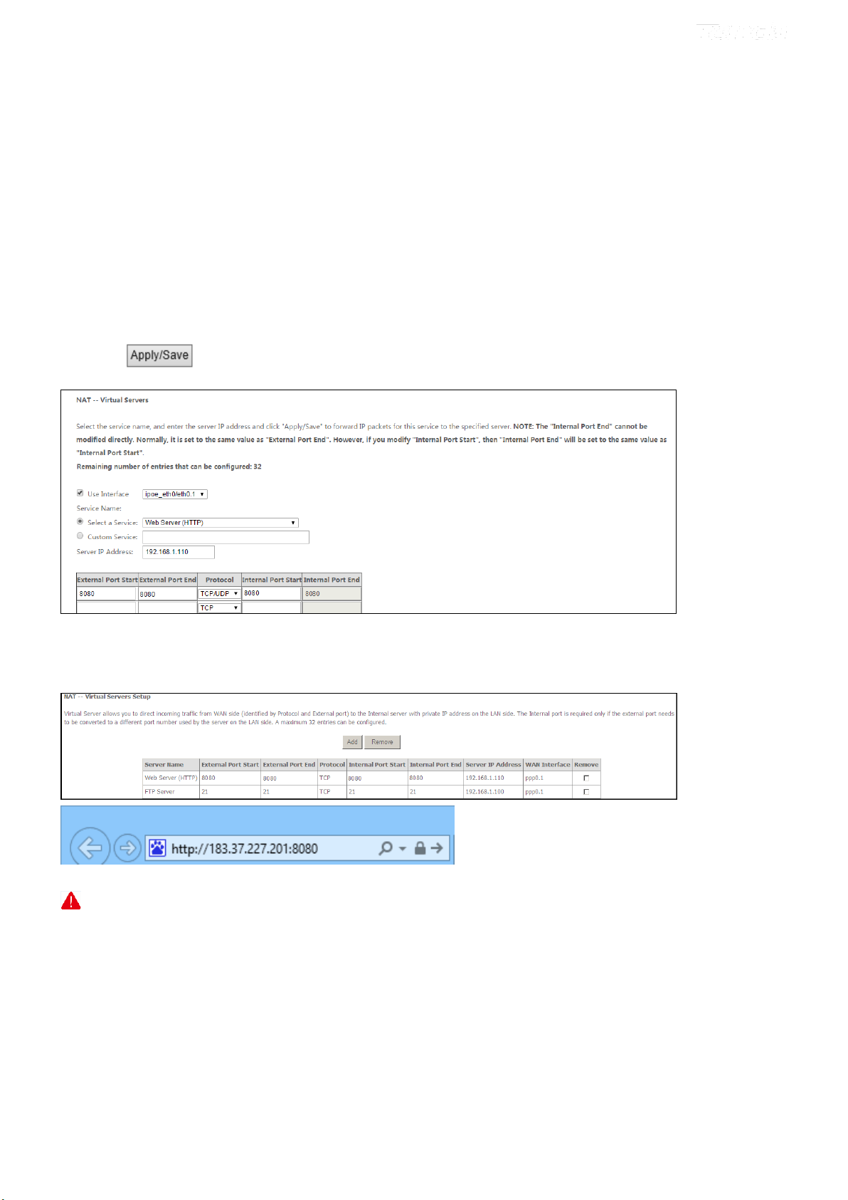
5. Click .
Your friends on the Internet will then be able to access your FTP server simply by "ftp://183.37.227.201:21".
83
Page 9
To configure your router to make your local web server public:
Procedure
1. Click NAT > Virtual Server to enter it and then click the Add button.
2. Select Web Server (HTTP) that you wish to host on your network from the Select a Service drop-down list. The
port number (8080) used by this service will then be automatically populated.
- Or if you wish to define the service yourself, enter a descriptive name in the Custom Service, say My Web Server
(HTTP), and then manually enter the port number (8080) used by this service in the Internal Starting Port,
Internal Ending Port, External Starting Port and External Ending Port fields.
3. Select a protocol from the Protocol drop-down list. If you are unsure, select TCP/UDP.
4. In the Server IP Address field, enter the last digit of the IP address of your local computer that offers this service.
Here in this example, we enter 110.
5. Click .
Now you can view your configurations as seen in the screenshot below. Your friends on the Internet will then be able to
access the web server simply by entering "http://183.37.227.201:8080" in his browser.
_________________________________________________________________________________________________
NOTE
1. The "Internal Port End" cannot be modified directly. Normally, it is set to the same value as "External Port End".
However, if you modify "Internal Port Start", then "Internal Port End" will be set to the same value as "Internal Port
Start".
2. If the service or game you wish to host on your network is not included in the list, manually add it in the Custom
Service field and then add the port number used by it to the Internal Starting Port, Internal Ending Port, External
Starting Port and External Ending Port fields.
_________________________________________________________________________________________________
84
Page 10

Port Triggering
Some applications such as games, video conferencing, remote access applications and others require that specific ports in
the Router's firewall be opened for access by the applications. Port Trigger dynamically opens up the 'Open Ports' in the
firewall when an application on the LAN initiates a TCP/UDP connection to a remote party using the 'Triggering Ports'.
The Router allows the remote party from the WAN side to establish new connections back to the application on the LAN
side using the 'Open Ports'.
To enter the Port Triggering screen, click NAT > Port Triggering and then click the Add button to add rules.
You can configure the port settings from this screen by selecting an existing application or creating your own (Custom
application) and click Save/Apply to add it.
Use Interface: Select a WAN connection to which you wish to apply the rules. When there is only one WAN connection
available, the rules will be automatically applied to it.
Application Name: Two options are available:
Select an application: Select one from the drop-down list directly.
- Custom application: Custom application by yourself.
Trigger Port Start/Trigger Port End: The port range for an application to initiate connections.
Trigger Protocol: Select the protocol from the drop-down list. If you are unsure, select TCP/UDP.
Open Port Start/ Open Port End: These are the starting number and ending number for the ports that will be
85
Page 11

automatically opened by the built-in firewall when connections initiated by an application are established.
DMZ Host
The default DMZ (De-Militarized Zone) host feature is helpful when you are using some online games and
videoconferencing applications that are not compatible with NAT (Network Address Translation).
DMZ Host IP Address: The IP Address of the device for which the router’s firewall will be disabled. Be sure to assign a
static IP Address to that device. The DMZ host should be connected to a LAN port of the device. Be sure to assign a
static IP address to that DMZ host.
Warning!
DMZ servers pose a security risk. A computer designated as the DMZ server loses much of the protection of the firewall
and is exposed to exploits from the Internet.
UPnP
UPnP (Universal Plug and Play) allows Windows based systems to configure the device for various Internet applications
automatically. UPnP devices can automatically discover the services from other registered UPnP devices on the network.
If you use applications such as multiplayer gaming, peer-to-peer connections, or real-time communications, like instant
messaging or remote assistance (a feature in Windows XP), you should enable UPnP.
86
Page 12

Enable UPnP: Check/uncheck to enable/disable the UPnP feature.
_________________________________________________________________________________________________
NOTE
UPnP is activated only when there is a live WAN service with NAT enabled.
_________________________________________________________________________________________________
4.2.5 Security
This section explains the following information:
• IP Filtering
• MAC Filtering
IP Filtering
Outgoing IP Filtering Setup
By default, all outgoing IP traffic from LAN is allowed, but some IP traffic can be BLOCKED by setting up filters.
Choose Add or Remove to configure outgoing IP filters.
Choose Add to enter the following screen:
87
Page 13

This screen allows you to create a filter rule to identify outgoing IP traffic by specifying a new filter name and at least
one condition below. All of the specified conditions in this filter rule must be satisfied for the rule to take effect. Click
to save and activate the filter.
Filter Name: Enter a descriptive filtering name.
IP Version: Support IPv4.
Protocol: TCP/UDP, TCP, UDP and ICMP are available for your option.
Source IP address [/prefix length]: Enter the LAN IP address to be filtered.
Source Port (port or port: port): Specify a port number or a range of ports used by LAN PCs to access the
Internet. If you are unsure, leave it blank.
Destination IP address [/prefix length]: Specify the external network IP address to be accessed by specified LAN
PCs.
Destination Port (port or port:port): Specify a port number or a range of ports used by LAN PCs to access external
network.
Incoming IP Filtering Setup
When the firewall is enabled on a WAN or LAN interface, all incoming IP traffic is BLOCKED. However, some IP
traffic can be ACCEPTED by setting up filters.
Choose Add or Remove to configure incoming IP filters.
88
Page 14

Click Add to enter the following screen:
This screen allows you to create a filter rule to identify incoming IP traffic by specifying a new filter name and at least
one condition below. All of the specified conditions in this filter rule must be satisfied for the rule to take effect. Click
to save and activate the filter.
IP Version: Select IP version.
Protocol: TCP/UDP, TCP, UDP and ICMP are available for your option.
Source IP address [/prefix length]: Enter the Internal IP address [/prefix length] to be filtered.
Source Port (port or port: port): Specify a port number or a range of ports used by PCs from external network to
access your internal network.
Destination IP address [/prefix length]: Specify the internal network IP address [/prefix length] to be accessed by
the specified PCs from external network.
Destination Port (port or port:port): Specify a port number or a range of ports used by PCs from external network
to access your internal network.
MAC Filtering
A bridge WAN service is needed to configure this service.
MAC Filtering is only effective on ATM PVCs configured in Bridge mode. FORWARDED means that all MAC layer
frames will be forwarded except those matching with any of the specified rules in the following table. BLOCKED means
that all MAC layer frames will be blocked except those matching with any of the specified rules in the following table.
Choose Add or Remove to configure MAC filtering rules.
89
Page 15

_________________________________________________________________________________________________
Warning!
Changing from one policy to another of an interface will cause all defined rules for that interface to be REMOVED
AUTOMATICALLY! You will need to create new rules for the new policy.
_________________________________________________________________________________________________
Click Add to enter the following screen:
Here you can create a filter to identify the MAC layer frames by specifying at least one condition below. If multiple
conditions are specified, all of them take effect. Click Save/Apply to save and activate the filter.
Protocol Type: Select a protocol type from the drop-down list.
Destination MAC Address: Enter the MAC address of data frame being restricted to arrive.
Source MAC Address: Enter the MAC address of data frame being restricted to come.
Frame Direction: Select a frame direction from the drop-down list.
WAN Interfaces: Select a WAN interface from the drop-down list.
4.2.6 Parental Control
This section explains the following information:
90
Page 16

• Time Restriction
• URL Filter
Time Restriction
Click Parental Control > Time Restriction > Add to enter the following screen.
Here you can add time of day restriction that an attached LAN device can access the Internet.
The Browser's MAC Address automatically displays the MAC address of the LAN device where the browser is running.
To restrict other LAN device, check the "Other MAC Address" option and enter its MAC address.
User Name: Enter a user name.
Browser's MAC Address: Automatically adds the MAC address of the attached LAN device where the browser is
running.
Other MAC Address: Specify the MAC address of the computer that you want to apply Internet access restriction.
Days of the week: Click to select the days of the week during which you wish to restrict Internet access.
Start Blocking Time/ End Blocking Time: Specify time of day restriction to an attached LAN device. Within this
specified time length of the day, this LAN device will be blocked from the Internet.
Apply/Save: Click to save and apply your settings.
URL Filter
Here you can add URL access restriction to specific LAN PCs.
91
Page 17

Select the URL List Type (Exclude or Include) first and then click Add to enter the screen below for configuring the list
entries.
URL Address: Enter a specific URL or a key word of domain name in this field.
Click to apply and save the settings.
_________________________________________________________________________________________________
NOTE
If you have accessed the URL before you include it in a URL filter rule, you must reboot the router and erase it from
your PC to activate this URL filter rule. To erase the domain name from your PC:
1. Click the keys +R on the keyboard to enable “Run” dialog, and type cmd > click OK.
(Note that different operation systems may have different ways to enable “Run”; Windows is taken a guide here.)
92
Page 18
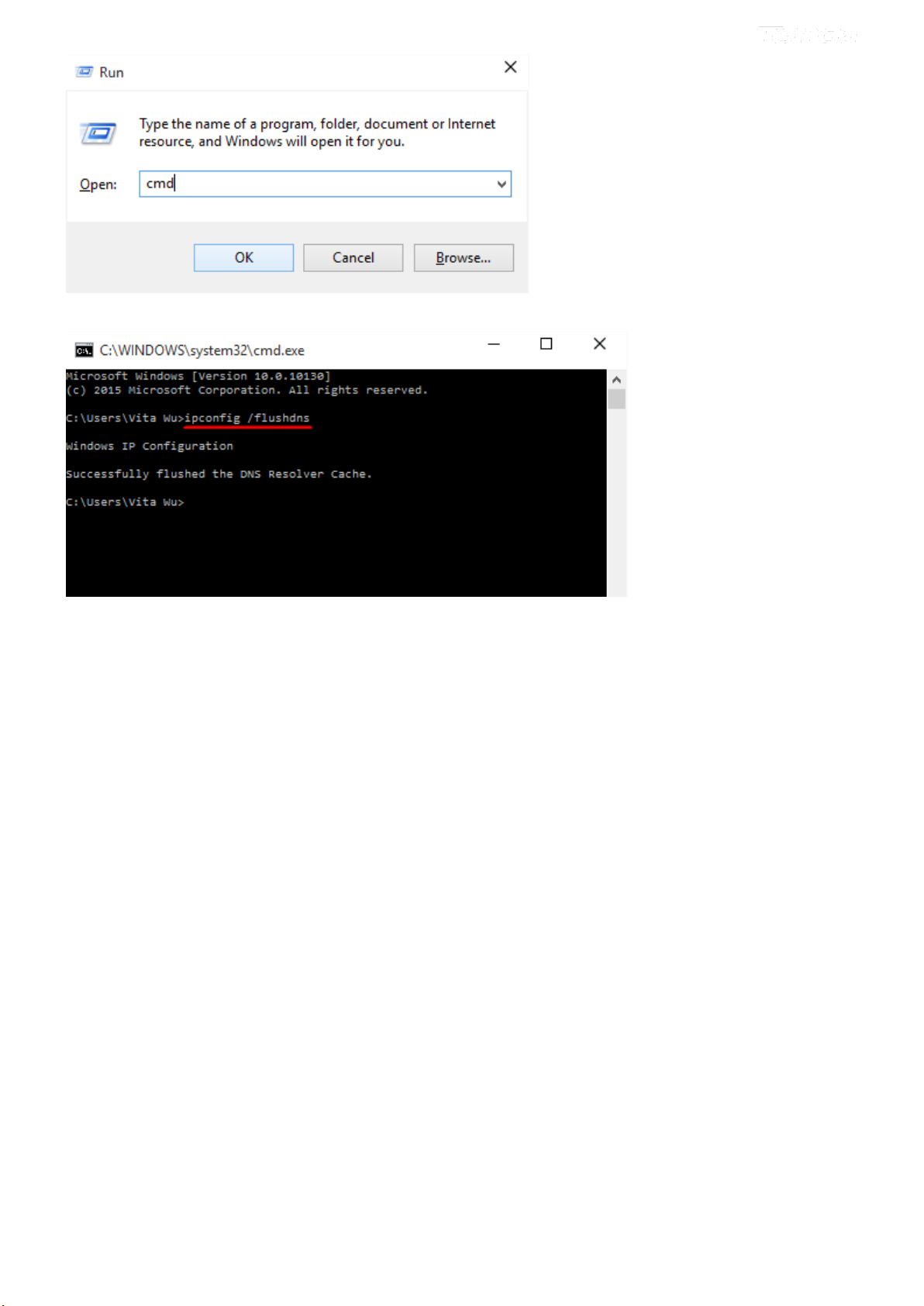
2. Then type ipconfig /flushdns and hit Enter on the keyboard.
_________________________________________________________________________________________________
4.2.7 Bandwidth Control
When multiple devices each of which requests a different bandwidth attach to the modem router, to ensure the attached
devices obtaining a fair bandwidth and getting a fluent Internet experience, set a bandwidth control rule.
Check Enable Bandwidth Control to enable this feature.
93
Page 19

Description: Name the bandwidth control rule as you like.
IP Address Range: Type the IP address range of target hosts. Follow the example .
If you want to set one host, follow the example .
Max Upstream Speed (Kbps): Set the upstream speed as your actual bandwidth need.
Max Downstream Speed (Kbps): Set the downstream speed as your actual bandwidth need.
Status: Enable or Disable.
After you have edited the details of the bandwidth control rule, click first to save and then click to
activate the settings.
4.2.8 Routing
This section explains the following:
• Default Gateway
• Static Route
Default Gateway
Default gateway interface list can have multiple WAN interfaces served as system default gateways but only one will be
used according to the priority with the first being the highest and the last one the lowest priority if the WAN interface is
connected. Priority order can be changed by removing all and adding them back in again.
Selected Default Gateway Interfaces: Displays the selected default gateway interfaces. Select a WAN interface
and click the button to move it to the Available Routed WAN Interfaces box.
94
Page 20

Available Routed WAN Interfaces: Displays the available routed WAN interfaces. Select a WAN interface and
click the button to add it to the Selected Default Gateway Interfaces box.
Apply/Save: Click to save and activate your settings.
Static Route
Static routes provide additional routing information to your router. Typically, you do not need to add static routes.
However, when there are several routers in the network, you may want to set up static routing. Static routing determines
the path of the data in your network. You can use this feature to allow users on different IP domains to access the Internet
via this device. It is not recommended to use this setting unless you are familiar with static routing. In most cases,
dynamic routing is recommended, because this feature allows the router to detect the physical changes of the network
layout automatically.
Click Add to enter the following screen:
IP Version: Select IP version.
Destination IP address/prefix length: Enter the destination IP address and prefix length of the final destination.
Interface: Select an interface from the drop-down list.
Gateway IP address: Enter the gateway IP address, which must be a router on the same LAN segment as the
95
Page 21

router.
Metric: Enter a number in the Metric field. This stands for the number of routers between your network and the
destination.
Apply /Save: Click to apply and save your settings.
_________________________________________________________________________________________________
NOTE
1. Destination IP address cannot be on the same IP segment as WAN or LAN segment as the router.
2. Only configure additional static routes for unusual cases such as multiple routers or multiple IP subnets located on
your network. Wrong static routes may lead to network failure.
3. For system created route, the “Remove” checkbox is disabled.
_________________________________________________________________________________________________
4.2.9 DNS
DNS Server (Static DNS)
The DNS server translates domain names to numeric IP addresses. It is used to look up site addresses based on their
names. If the DNS server works incorrectly, Internet access will be blocked.
DNS server is configured when you are setting up your Internet connectivity. So, you do not have to finish DNS server
setup here unless your network works false.
For IPv4
① Click Advanced Setup > DNS > DNS Server, and enter the screen below.
96
Page 22
② Check the Select DNS Server Interface from available WAN interfaces option if the device gets a DNS
address automatically from an upstream device. Or select the Use the following Static DNS IP address option and
enter static DNS server address provided by your ISP.
③ Click Apply/Save at the bottom of the page.
For IPv6
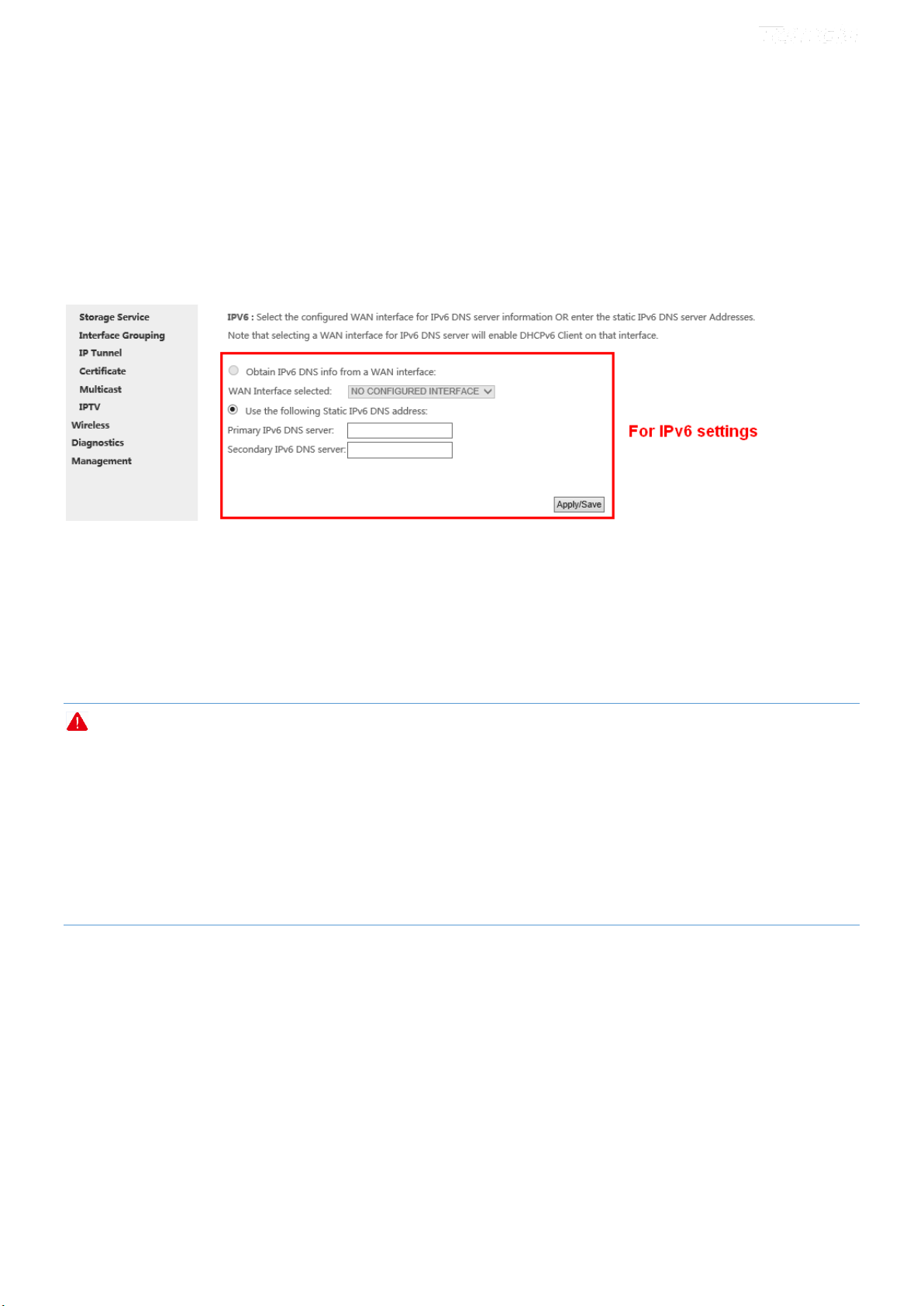
① Click Advanced Setup > DNS > DNS Server, and enter the screen below.
② Select the Obtain IPv6 DNS info from a WAN interface option if the device gets a DNS server address from
the upstream device automatically. And select a configured WAN interface for the IPv6 DNS server information.
Or select the Use the following Static IPv6 DNS address option and enter the static IPv6 DNS server address
provided by your ISP.
③ Click Apply/Save.
NOTE
1. In ATM mode, if only a single PVC with IPoA or static IPoE protocol is configured, Static DNS server IP addresses
must be entered.
2. If you are not clear about the static DNS server IP information, ask your ISP to provide it.
3. The default settings are recommended if you are unsure about the DNS server addresses. If a wrong DNS server
address is configured, webpages may not be open.
Dynamic DNS (DDNS)
If your Internet service provider (ISP) gave you a static (fixed) public IP address, you can register a domain name and
have that name associated with your IP address by public Domain Name Servers (DNS). However, if your ISP gave you
a dynamic (changing) public IP address, you cannot predict what your IP address will be, and the address can change
frequently. In this case, you can use a commercial Dynamic DNS service. It allows you to register your domain to their
IP address and forward traffic directed at your domain to your frequently changing IP address. If your ISP assigns a
private WAN IP address (such as 192.168.x.x or 10.x.x.x), the Dynamic DNS service does not work because private
97
Page 23

addresses are not routed on the Internet.
Click Advanced Setup > DNS > Dynamic DNS to enter the Dynamic DNS screen.
Click to configure the DDNS settings.
D-DNS Provider: Select your DDNS service provider from the drop-down menu.
Hostname: Enter the DDNS domain name registered with your DDNS service provider.
Interface: Specify a WAN connection interface.
Username: Enter the DDNS user name registered with your DDNS service provider.
Password: Enter the DDNS Password registered with your DDNS service provider.
Click to save your settings.
Example: dyn.com
Hostname: tenda.dyndns.org
Username: tenda
Password: 123456789
Add Dynamic DNS
① Select dyn.com from the D-DNS provider drop-down menu.
98
Page 24

② Enter the hostname. Here is “tenda.dyndns.org” for example.
③ Specify a WAN connection interface.
DynDNS Settings
④ Enter your DynDNS username. Here is “tenda”
for example.
⑤ Enter the password of DynDNS account.
Here is “123456789” for example.
⑥ Click to save your configuration.
4.2.10 DSL
This screen provides multiple ASDL modulation modes to meet diversified environments. You can also select phone line
pair and Capability.
DSL parameter configurations must be supported by ISP to take effect. Actual parameters (see Statistics-DSL) resulted
from the negotiation between your router and ISP. Wrong configurations may fail your Internet access.
The best DSL configurations are the factory defaults. Only change them with the support of your ISP or our technical
staff when your router fails to negotiate with ISP in DSL (ATM) mode.
99
Page 25

Check the checkbox next to a modulation to enable it and then click .
Advanced Settings: Click it to enter the Advanced Settings screen as below.
Here you can select the test mode and tone.
_________________________________________________________________________________________________
TIP
If you are unsure about the DSL parameters, please apply the factory default settings. Wrong configurations may fail
your Internet access.
_________________________________________________________________________________________________
4.2.11 Storage Service
This section explains the following:
• Storage Device Info
• User Account
The modem router provides a USB port. You can attach a USB storage device to it and share your USB device with a
user in the LAN.
Storage Device Info
Once you plug your USB storage device into the USB port, the details about the USB storage will be recorded shown as
below table.
100
Page 26
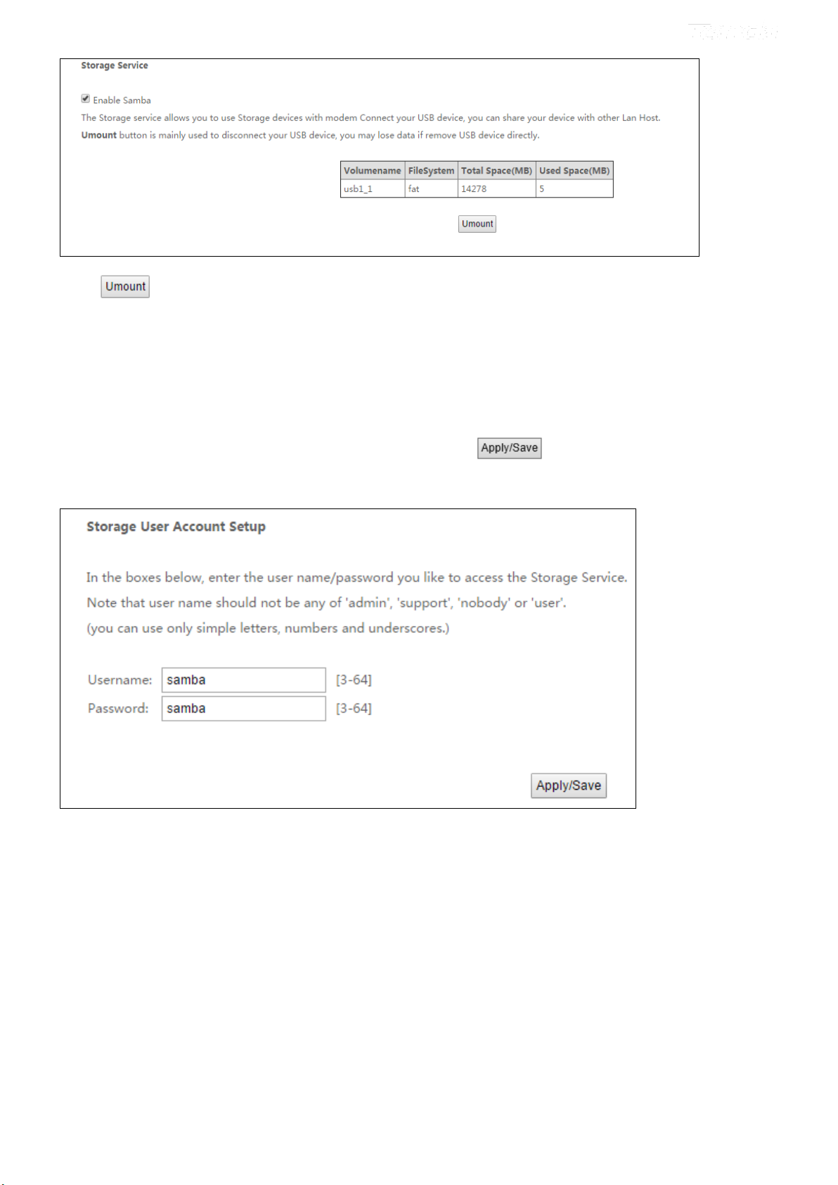
Click and then uplug your USB device. Removing directly may damage your USB storage device.
User Account
Accessing the USB storage device requires an account. You can click to use the default account or you can
customize a new one. Pay attention to that your computer system will record the account you used at the first time.
Application: How to access the USB storage device attached to the
modem router?
Step 1: Plug USB storage device.
Plug your USB storage device into the USB port, and make sure the USB LED indicator is on.
Step 2: Create an account.
Go to User Account interface, and set up your account. Here the default account “samba” is kept. And click
101
Page 27
to save and apply.
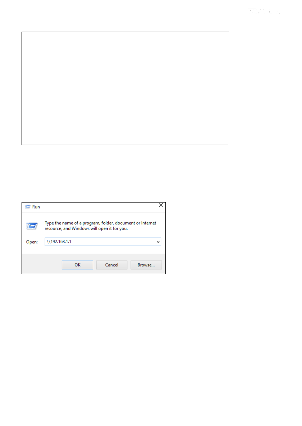
Step 3: Access the USB storage device from a computer.
Click +R on the keyboard to pop up the Run dialog, and type \\192.168.1.1 in the blank field.
Click OK.
Step 4: Access the USB storage device with the account “samba”.
Double click , and enter your account “samba” and password to finish the credentials. Then, click OK.
102
Page 28

Access successfully!
4.2.12 Interface Grouping
Interface Grouping supports multiple ports to PVC and bridging groups. Each group will perform as an independent
network. To support this feature, you must create mapping groups with appropriate LAN and WAN interfaces using the
Add button. The Remove button will remove the grouping and add the ungrouped interfaces to the Default group.
103
Page 29

Click Add to enter the screen below:
Group Name: Define a name for group.
WAN Interface used in the grouping: WAN connection to which the interface grouping rules apply.
Available LAN Interfaces: LAN interfaces which are available for interface grouping.
Grouped LAN Interfaces: LAN interfaces which are classed into the specified WAN connection.
To create a new interface group:
① Enter the Group name and the group name must be unique.
② Select an available WAN interface for the LAN network proxy.
③ Define the available LAN interface to connect to the specified WAN interface. Select interfaces from the
Available LAN Interfaces list and add it to the Grouped LAN Interfaces list using the arrow buttons to create the
required mapping of the ports.
④ Click Apply/Save button to make the changes effective immediately.
If you want to bypass NAT via the router’s interface and obtain the public IP address automatically, you need to add the
DHCP vendor ID in the Automatically Add Clients with the following DHCP Vendor IDs section. After the ID takes
effect, your router will automatically detect the DHCP request from computers on the LAN, and it will forward the
DHCP vendor ID and the corresponding DHCP request to the WAN interface used in the interface rules.
NOTE
1. Eth0, eth1, eth2 and eth3 respectively represent 1/WAN, 2, 3 and 4/iTV port of the device. And wlan0 is the port
for all wireless devices connecting to the modem router.
2. If a vendor ID is configured for a specific client device, please REBOOT the client device attached to the
modem to allow it to obtain an appropriate IP address.
3. No Interface/None indicates that there is no WAN port.
104
Page 30

4.2.13 IP Tunnel
This section explains the following information:
• IPv6inIPv4
• IPv4inIPv6
IPv6inIPv4
Click IPv6inIPv4 and Add to enter the following screen:
Tunnel Name: Specify the name of the tunnel.
Mechanism: Currently, only 6RD configuration is supported.
Associated WAN Interface: Specify the WAN interface of the tunnel.
Associated LAN Interface: Specify the LAN interface of the tunnel.
Manual: If you select Manual, configure the following settings also:
IPv4 Mask Length: Specify the IPv4 Mask Length.
6rd Prefix with Prefix Length: Specify the 6rd Prefix with Prefix Length.
Border Relay IPv4 Address: Specify the Border Relay IPv4 Address.
Automatic: If Automatic is selected, no configurations are required.
Apply/Save: Click to apply and save your settings.
105
Page 31

IPv4inIPv6
Click IPv4inIPv6 and Add to enter the following screen:
Tunnel Name: Specify the name of the tunnel.
Mechanism: Currently, only DS-Lite configuration is supported.
Associated WAN Interface: Specify the WAN interface of the tunnel.
Associated LAN Interface: Specify the LAN interface of the tunnel.
Manual: If you select Manual, enter the AFTR information also:
Automatic: If Automatic is selected, no configurations are required.
Apply/Save: Click to apply and save your settings.
4.2.14 Certificate
This section explains the following information:
• Local Certificates
• Trusted CA (Certificate Authority) Certificates
Local Certificates
Here you can add, view or remove certificates. Local certificates are used by peers to verify your identity. Maximum 4
106
Page 32

certificates can be stored.
To generate a certificate signing request:
① Click the Create Certificate Request button to enter the page below.
② Specify the Common Name, Organization Name and State/Province Name
③ Enter the 2-letter Country Code for the certificate.
④ Click Apply to apply your settings.
To Import certificate:
① Click the Import Certificate button on the local certificates page to enter the page below.
107
Page 33

② Enter the certificate name.
③ Paste the certificate content and private key.
④ Click Apply to apply your settings.
Trusted CA (Certificate Authority) Certificates
Here you can add, view or remove CA certificates. CA certificates are used by you to verify peers' certificates. Maximum
4 certificates can be stored.
108
Page 34

To Import certificate:
① Click the Import Certificate button to enter the page below.
② Enter the certificate name.
③ Paste the certificate content.
④ Click Apply to apply your settings.
4.2.15 Multicast
Here you can configure the multicast feature.
To configure IGMP for IPv4
① Check the LAN to LAN (Intra LAN) Multicast Enable box.
② Check the Membership Join Immediate (IPTV) box. This is only required for IPTV.
③ Keep other options unchanged from factory defaults if you are not an advanced user. This is strongly
recommended.
109
Page 35

To configure IGMP for IPv6
① Check the LAN to LAN (Intra LAN) Multicast Enable box.
② Keep other options unchanged from factory defaults if you are not an advanced user. This is strongly
recommended.
110
Page 36

4.2.16 IPTV
If you check the Enable IPTV checkbox, you must choose a layer2 interface, and then configure the PVC info (ATM),
or VLAN info (ETH). Click to save it.
Enable IPTV: Check to enable the IPTV service, or disable it.
IPTV configuration for DSL Internet Access user:
① Enable IPTV.
② Select Layer2 interface: ATM Interface.
③ Configure an available VPI/VCI value which should be provided by your ISP.
④ Click .
IPTV configuration for Ethernet Internet Access user:
① Enable IPTV.
② Select Layer2 Interface: ETH Interface.
③ Click .
111
Page 37

After successful IPTV configurations, Port 4/iTV on the back panel of the device can only be an IPTV port.
_________________________________________________________________________________________________
TIP
For tagged service, enter valid 802.1P Priority and 802.1Q VLAN ID.
For untagged service, set -1 to both 802.1P Priority and 802.1Q VLAN ID.
_________________________________________________________________________________________________
4.3 Wireless
This section explains the following information:
• Basic
• Security
• MAC Filter
• Wireless Bridge
• Station Info
4.3.1 Basic
This page allows you to configure basic features of the wireless LAN interface. You can enable or disable the wireless
LAN interface, hide the network from active scans, set the wireless network name (also known as SSID) and restrict the
channel set based on country requirements.
Click to configure the basic wireless options.
112
Page 38

Enable Wireless: check/uncheck to enable/disable the wireless feature.
Hide Access Point (Hide SSID): This option allows you to have your network names (SSID) publicly broadcast. If
you choose to enable it, the SSID will be hidden.
SSID: This is the public name of your WiFi.
BSSID: Display the MAC address of the wireless network.
Country: Select your country.
Channel: Select a channel, or select Auto to let system automatically select one for your wireless network to
operate on if you are unsure. The best selection is a channel that is the least used by adjacent networks.
Bandwidth: Configure the wireless bandwidth. The default is 40MHz.
RF Power: Normal or Enhance. This option may adjust the wireless signal strength.
4.3.2 Security
This page allows you to configure security features of the wireless LAN interface. You may set up configuration
manually or through WiFi Protected Setup (WPS).
113
Page 39

WPS Setup
Wi-Fi Protected Setup makes it easy for home users who know little of wireless security to establish a home network, as
well as to add new devices to an existing network without entering long passphrases or configuring complicated settings.
Enable WPS: This is WPS ON/OFF turn. Click it to enable or disable WPS. WPS is disabled by default.
Device PIN: This is PIN code of the modem router for WPS PIN mode.
Enter SAT PIN: “SAT” means the remote wireless client requiring a connection. Enter its PIN code in the blank if you
select this option, and then click .
Use AP PIN: “AP” means the modem router. Select this option if you copy the PIN code of the modem router to the
remote wireless client.
NOTE
1. WPS/RST button in the device back panel: When WPS feature is enabled, press this button on the device for 1~3
seconds and the WPS LED will keep blinking for about 2 minutes. Within the 2 minutes, press the WPS button on
your wireless clients. When the WPS displays a solid light, the wireless client has joined in your wireless network.
2. To use the WPS security, the wireless client must be also WPS-capable.
3. WPS only supports WPA2, which means only when you select “WPA2” encryption or “Open” you can change WPS
status.
114
Page 40

Manual Setup AP
You can set the network authentication method, selecting data encryption, specify whether a network key is required to
authenticate to this wireless network and specify the encryption strength.
Click when done.
Network Authentication: Select Open, Shared, WPA-PSK, WPA2-PSK or Mixed WPA/ WPA2-PSK from the
drop-down list to encrypt your wireless network.
Depending on the type of network authentication you select, you will be prompted to enter corresponding settings.
WEP Encryption: Select Enabled or Disabled.
Encryption Strength: Select 128-bit or 64-bit.
Current Network Key: Select a network key to be active.
Network Key 1/2/3/4: Enter 13 ASCII characters or 26 hexadecimal digits for 128-bit encryption keys; enter 5
ASCII characters or 10 hexadecimal digits for 64-bit encryption keys.
WPA/WAPI passphrase: Enter a WPA/WAPI network key.
WPA Group Rekey Interval: Specify a key update interval.
WPA/WAPI Encryption: Select AES or TKIP+AES.
115
Page 41

4.3.3 MAC Filter
The MAC-based Wireless Access Control feature can be used to allow or disallow clients to connect to your wireless
network.
MAC Restrict Mode: Disabled, Allow and Deny
Allow: Only allow PCs at specified MAC addresses (in the list) to connect to your wireless network.
Deny: Block only PCs at specified MAC addresses from connecting to your wireless network.
Disable: Disable this feature.
Add: Click it to add a MAC address.
Remove: To delete an existing MAC address, first check the Remove box next to the MAC address in list and then click
this button.
Example 1: To allow only the PC at the MAC address of 00:1A:3D:9C:BB:23 to connect to your wireless network, do
as follows:
① Select Allow, and click .
② Click the Add button.
116
Page 42

③ Enter 00:1A:3D:9C:BB:23 in the MAC address box as shown in the figure below, and click
Set up successfully!
________________________________________________________________________________________________
NOTE
If “Allow” mode is activated with no MAC address being limited, WPS feature will be disabled. Go to Wireless >
Security to check WPS status).
________________________________________________________________________________________________
4.3.4 Wireless Bridge
This page allows you to configure wireless bridge (also known as Wireless Distribution System) features of the wireless
interface.
Wireless distribution system (WDS) is a system enabling the wireless interconnection of access points in an IEEE 802.11
network. It allows a wireless network to be expanded using multiple access points without the traditional requirement for
a wired backbone to link them.
117
Page 43

AP Mode: You can select Wireless Bridge (also known as Wireless Distribution System) to disable access point
functionality. Selecting Access Point enables access point functionality. Wireless bridge functionality will still be
available and wireless stations will be able to associate to the AP.
Bridge Action: There are three options available: Enabled, Enabled (Scan) and Disabled. Disabled mode means
disabling the wireless bridge function. If Enabled mode is selected, you need to enter the remote device MAC address
manually. If Enabled (Scan) is selected, the system automatically scans the remote device MAC address and SSID.
Remote Bridges MAC Address: Here displays the remote device info, MAC address and SSID (if Bridge Action is
Enabled Scan), or offers you field to enter the remote info, MAC address (if Bridge Action is Enabled).
Refresh: Click to refresh the Wireless Name (SSID). Wait for few seconds to refresh.
Apply/Save: Click to apply and save the settings.
Instance
Assume that there is a wireless router in your living room, far away from your study room. Every time you join the WiFi
in the study room, it seems hard for you to watch a high-quality live streaming video. To add another wireless router in
the study room is an ideal choice to solve your problem. Wireless Bridge function of the modem router helps you to
extend your wireless coverage, speed up downloading. Then your video will run smoother and faster.
Assume that the router in your living room is Router 1, and the other one in study room is Router 2.
118
Page 44

Before you get started:
① View and note down the security settings of Router 1: wireless name (SSID), channel, security mode, MAC
address and wireless key.
a) Click Advanced > Wireless > Basic to check the SSID, MAC address (BSSID) and Channel.
SSID: Tenda_112252
BSSID: 00:90:4C:11:22:53
Channel: 6
b) Click Advanced > Wireless > Security to check security mode and wireless key.
119
Page 45

WPS: Disable
Security Mode: WPA2-PSK / AES
Wireless Key: 12345678
② View the LAN settings of Router 1.
Click Advanced > Advanced Setup > LAN to check LAN IP address and Subnet Mask, and verify that the DHCP
Server is enabled.
LAN IP Address: 192.168.1.1;
Subnet Mask: 255.255.255.0
120
Page 46

After you prepare two steps above, do as follows:
Configure Router 2:
① Set the LAN IP address of Router 2 to a different IP address yet on the same segment as Router 1.
Click Advanced > Advanced Setup > LAN to change the LAN IP address into 192.168.1.10.
Disable your DHCP server.
② Click Advanced > Wireless > Basic to check the SSID and Channel. They should be the same as Router 1’s. If
not, correct them manually. Click Apply/Save to save your settings.
③ Click Advanced > Wireless > Security to check the security mode and wireless key. Verify that they are the
same as Router 1’s. If not, correct them manually. Click Apply/Save to save your settings.
④ Click Advanced > Wireless > Wireless Bridge to configure wireless bridge.
Access Point (Recommended):
Two ways to bridge Router 1 by using Access Point:
a. If you select Enable in Bridge Action field.
121
Page 47

Enter the MAC address of Router 1 which you have noted down (00:90:4C:11:22:53).
Then click Apply/Save to save the settings.
b. If you select Enable(Scan) in Bridge Action field.
Select the SSID of Router 1 (Tenda_112252) in Remote Bridges MAC Address field.
If you cannot find the SSID on the list, click Refresh to refresh the list.
Then click Apply/Save to save your settings.
Wireless Bridge
Two ways to bridge Router 1 by using Wireless Bridge:
a. If you select Enable in Bridge Action field.
Enter the MAC address of Router 1 which you have noted down (00:90:4C:11:22:53).
Then click Apply/Save to save the settings.
122
Page 48

b. If you select Enable(Scan) in Bridge Action field:
Select the SSID of Router 1 (Tenda_112252) in Remote Bridges MAC Address field. If you cannot find the
SSID on the list, click Refresh to refresh the list.
Then click Apply/Save to save your settings.
After you fininsh the settings on Router 2 above, do as follows:
Configure Router 1:
① Click Advanced > Wireless > Wireless Bridge.
② Select Access Point in AP Mode field. (If you select Wireless Bridge here, the wireless devices will not be
able to connect Router 1 wirelessly.)
If AP Mode of Router 2 is Access Point, there are two ways to bridge Router 2.
a. If you select Enable in Bridge Action field:
Enter the MAC address of Router 2 which you can check on Wireless > Basic interface, say BSSID
(02:10:18:01:00:02).
123
Page 49

Then click Apply/Save to save the settings.
b. If you select Enable(Scan) in Bridge Action field:
Select the SSID of Router 2 (Tenda_112252) in Remote Bridges MAC Address field.
If you cannot find the SSID on the list, click Refresh to refresh the list.
Then click Apply/Save to save your settings.
The configuration is finished. Then the devices can connect Router 2 wirelessly or via Ethernet cables.
If AP Mode of Router 2 is Wireless Bridge, you can only select Enable and enter the MAC address (02:10:18:01:00:02)
to bridge Router 2.
124
Page 50

The configuration is finished. Then the devices can only connect Router 2 via Ethernet cables.
NOTE
The WDS feature (also known as Wireless Bridge) can only be implemented between 2 WDS-capable wireless devices.
Plus, SSID, channel, security settings and security key must be exactly the same on both such devices.
4.3.5 Station Info
This page shows authenticated wireless stations and their status.
4.4 Diagnostics
this part includes the following information:
Diagnostics
Ping test
125
Page 51

4.4.1 Diagnostics
The device is capable of testing the connection to your DSL service provider, the connection to your Internet service
provider and the connection to your local network. If a test displays a fail status, click “Rerun Diagnostic Tests” at the
bottom of this page to make sure the fail status is consistent. If the test continues to fail, click “Help” and follow the
troubleshooting procedures.
Pass: Indicates that the Ethernet interface from your computer is connected to the LAN port of the device.
Fail: Indicates that the device does not detect the Ethernet interface on your computer.
4.4.2 Ping test
Ping utility can help test whether the device has built a proper connection with your host.
Type in the IP address of your host in the Ping IP Address field, and click Ping. If you get a similar screen shown as
below, it indicates the connection between the Ping object (Here is 192.168.1.2) and the device has been established.
126
Page 52

4.5 Management
This section explains the following information:
• Settings
• System Logs
• SNMP Agent
• TR-069 Client
• Internet Time
• Access Control
• Update Software
• Reboot
4.5.1 Settings
This section explains the following information:
• Backup
• Restore Backup
• Restore Default
Backup
Here you can save a copy of your device’s configurations to your computer. Once you have configured the device, you
can save these settings to a configuration file on your local hard drive. The configuration file can later be imported to
your device in case the device is reset to factory default settings.
127
Page 53

Restore Backup
Here you can restore the configurations of the modem router from a file saved on your PC.
Restore Default
Under some circumstances (for example, join a different network or unfortunately forgetting the login password), you
may need to remove the existing configuration and restore the factory default settings.
4.5.2 System Logs
The System Log dialog allows you to view the system log and configure the system log options.
128
Page 54

To configure the system log, click Configure System Log.
Log: If Enable is selected, the system will begin to log all the selected events.
Log Level: Set the log level. All events above or equal to the selected level will be logged.
Display Level: Set the log display level. All logged events above or equal to the selected level will be displayed.
Apply/Save: click to apply and save the system log settings.
To view the system log, firstly ensure log is enabled, otherwise you cannot read any log.
4.5.3 SNMP Agent
Simple Network Management Protocol (SNMP) allows a management application to retrieve statistics and status from
the SNMP agent in this device.
129
Page 55

SNMP Agent:Select “Enable” to activate the SNMP Agent feature or “Disable” to deactivate it.
Read Community: Specify a Read Community string. The default is public.
Set Community: Specify a Set Community string. The default is private.
System Name: Specify a descriptive system name.
System Location: Specify a system location.
System Contact: Specify a system contact.
Trap Manager IP: Specify the IP address of the Trap Manager.
4.5.4 TR-069 Client
WAN Management Protocol (TR-069) allows an Auto-Configuration Server (ACS) to perform auto-configuration,
provision, collection, and diagnostics to this device.
Click the TR-069 Client tab to enter the TR-069 Client configuration screen as seen below:
130
Page 56

Inform: Select Enable/Disable to enable/disable the TR-069 Client function. By default, it is disabled.
Inform Interval: Specify the inform interval.
ACS URL: Enter the ACS (Auto-Configuration Server) URL address.
ACS User Name: Enter the ACS (Auto-Configuration Server) user name.
ACS Password: Enter the ACS (Auto-Configuration Server) password.
WAN Interface used by TR-069 client: Select the WAN interface used by the TR-069 client from the drop-down
list.
Display SOAP messages on serial console: If Enable is selected, SOAP messages will be displayed on serial
console; if Disable is selected, SOAP messages will not be displayed on serial console.
Connection Request Authentication: Check/uncheck to enable/disable the connection request authentication.
Connection Request User Name: Enter the connection request user name.
Connection Request Password: Enter the connection request password.
Connection Request URL: Specify the connection request URL.
4.5.5 Internet Time
This page is used to set the router’s system time. If Automatically synchronize with Internet time servers is checked,
the system will automatically connect to NTP server to synchronize the time.
First/Second/Third/Fourth/Fifth NTP time server: Select a NTP time server from the drop-down list. If the NTP time
server you are looking for is not included in the list, select “Other” and then enter it manually in the box.
Time zone offset: Select your time zone from the drop-down list.
131
Page 57

4.5.6 Access Control
This section explains the following information:
• Password
• AccessControl - Service
Password
Access to your broadband router is controlled through two user accounts: admin and support.
Admin has unrestricted access to change and view configuration of your Broadband Router.
Support is used to allow a professional technician to access your Broadband Router for maintenance and to run
diagnostics.
User Name: Enter the user name of up to 16 characters. The default is “admin”.
Old Password: Enter the old password of up to 16 characters. The default is “admin”.
New Password: Enter a new password of up to 16 characters.
Confirm Password: Re-enter to confirm the new password.
Apply/Save: Click to change or create passwords.
_________________________________________________________________________________________________
NOTE
Password cannot contain a space.
_________________________________________________________________________________________________
132
Page 58

Access Control - Service
Here you can manage the device either from LAN or WAN side using HTTP, ICMP, TELNET, SNMP, FTP, TFTP and
HTTPS.
_________________________________________________________________________________________________
NOTE
If you are not an advanced user, it is recommended to keep the default settings.
________________________________________________________________________________________________
4.5.7 Update Software
Firmware upgrade is released periodically to improve the functionality of your device and add any new features. If you
run into a problem with a specific feature of the device you could log in to our website (www.tendacn.com) to download
the latest firmware to update your device.
133
Page 59

This modem router supports three types to update firmware.
Type 1: General Update
To update software, do as follows:
① Obtain an updated software image file from our website: www.tendacn.com.
134
Page 60

② Click the "Browse" button to locate the firmware file.
③ Click to start updating.
Type 2: Updating Via FTP Server
Updating via FTP server is supported. Make sure there is an available FTP server.
① Type the FTP Server IP address, like the right figure
② Type the port the FTP server used.
③ Type the user name and password to access the FTP
server.
④ Copy the name of the firmware.
⑤ Click to start updating.
Type 3: Updating Via TFTP Server
Updating via TFTP server is supported. Make sure there is an available TFTP server.
① Type the TFTP Server IP address in the field.
② Copy the name of the firmware.
③ Click to start updating.
135
Page 61

NOTE
The update process will cost 2 minutes, and the device will reboot.
4.5.8 Reboot
Click the Reboot button to reboot the router.
136
Page 62

Appendix 1 Applications
Application 1: How to change SSID and wireless password?
① Go to Wireless > Basic interface.
② Specify a SSID as you like, like Tenda_myhome.
③ Click Apply/Save to save the settings.
④ Go to Wireless > Security interface.
⑤ Choose a network authentication (WPA2-PSK is recommended) and set a passphrase.
⑥ Click Apply/Save to save the settings.
137
Page 63

Application 2: How to reset the modem router?
The device supports two methods to reset to factory defaults. Note that after you reset the device, you should reconfigure
it for Internet service.
Method 1: WPS/RST button
Press the WPS/RST button on the back of the modem router for about 8 seconds to reset it to factory defaults.
Method 2: Restore Default Settings from User Interface
① Go to Management > Settings > Restore Default to enter the interface below.
② Click icon to start resetting. And wait for the processing bar completing…
138
Page 64

Appendix 2 Configure Your PC
TIP: If you cannot find the icon
or , go to Control Panel and find
Network and Internet.
This part is just for your references when your computer connecting to the modem router cannot get an IP address.
Screens to configure TCP/IP properties in other Operating Systems are similar to those below.
Windows 8
1. Right click the icon or on the bottom right corner of your desktop.
2. Click Open Network and Sharing Center.
3. Click Ethernet > Properties.
139
Page 65

4. Find and double click Internet Protocol Version
4(TCP/IPv4).
5. Select Obtain an IP address automatically and Obtain
DNS server address automatically and click OK.
6. Click OK on the Ethernet Properties window (see Step 4 for the screenshot).
140
Page 66

Windows 7
1. Click the icon on the bottom right corner of your desktop.
2. Click Open Network and Sharing Center.
3. Click Local Area Connection >
Properties.
4. Find and double click Internet Protocol Version
4(TCP/IPv4).
141
Page 67

5. Select Obtain an IP address automatically and Obtain
DNS server address automatically and click OK.
6. Click OK on the Local Area Connection Properties window (see Step 4 for the screenshot).
142
Page 68

MAC
1. Click on the Apple icon from the top-left corner and select System
Preferences.
2. Click Network.
3. Click on Ethernet.
4. Select Using DHCP.
5. Click Apply.
143
Page 69

Appendix 3 Join Your Wireless Network
TIP:
1. If you cannot find the icon , please move your mouse to the top right corner of your desktop,
select Settings > Control Panel > Network and Internet > Network and Sharing Center >
Change adapter settings, right click Wi-Fi and select Connect/Disconnect.
2. If you cannot find your wireless network from the list, ensure the Airplane Mode is not enabled
on your PC.
Windows 8
1. Click the icon on the bottom right corner of your desktop.
2. Select your wireless network from the list, click Connect and then follow
onscreen instructions.
3. When your wireless network is connected successfully, the following
screen will appear.
144
Page 70

Windows 7
1. Click the icon on the bottom right corner of your desktop.
2. Double click your SSID (wireless network name) and then follow
onscreen instructions.
3. When your SSID (wireless network name) displays Connected as
shown below, you’ve connected to it for Internet access
successfully.
145
Page 71

MAC
1. Click > System Preferences.
2. Select Network from Internet & Network.
3. Click WiFi.
4. Turn WiFi on.
5. Click No network selected.
6. Select the wireless network name
of your router.
7. Enter the wireless password and click Join.
146
Page 72

iPhone/iPad
1. Scroll screen to find the Settings icon and click it.
2. Click WiFi, and turn on WiFi.
3. Find the name of the wireless network you wish to
connect, and click it.
4. Enter the wireless password and click Join.
Connected successfully!
147
Page 73

Appendix 4 FAQs
1. What information should I have to access the Internet via the DSL uplink?
If you have DSL broadband service, you might need the following information to set up your modem router.
• Active Internet service provided by a DSL account
• The ISP configuration information for your DSL account
- ISP login name and password
- Fixed or static IP address
Depending on how your ISP set up your Internet account, you could need to know the Virtual path identifier (VPI) and
virtual channel identifier (VCI) parameters for a manual setup.
2. I cannot access the device's User Interface (UI). What should I do?
1) Verify the physical connection (namely, the Ethernet cable) between your PC and the modem router. For details, see
Chapter 2 Hardware Installation hereof.
2) Double check the TCP/IP settings on your PC. For details, see Appendix 2 Configure Your PC hereof.
3) Press the WPS/RST button on the device for about 8 seconds and then re-access the UI with the default login info
“admin”.
4) Change the Ethernet cable that connects your PC and the device.
5) Try accessing device management interface from other PCs, smart phones or iPads.
6) Connect your PC alone to one of the LAN ports on the device.
3. What can I do if I forget my password?
1) If you forgot your login password, restore the device to its factory default settings and then use the default User
Name “admin” and Password “admin” to log in.
2) If you forgot your wireless network password, log in to the device User Interface, and go to Wireless > Security to
check or change your password.
4. Why cannot I connect to the searched wireless network?
1) Verify that you entered a correct security key.
2) Log in to the device, select Advanced > Wireless and change the wireless network name (SSID). Then connect
again.
3) Log in to the device, select Advanced > Wireless > Security and change the security settings. Then connect again.
148
Page 74

Appendix 5 VPI/VCI List
Country
ISP
VPI
VCI
Encapsulation
Australia
Telstra
8
35
PPPoA LLC
Australia
GoldenIT
8
35
PPPOA_VCMUX
Australia
Telstra Bigpond
8
35
PPPOE_LLC
Australia
OptusNET
8
35
PPPOE_VCMUX
Australia
AAPT
8
35
PPPOE_VCMUX
Australia
ADSL Direct
8
35
PPPOE_LLC
Australia
Ausie Broadband
8
35
PPPOE_LLC
Australia
Australia On Line
8
35
PPPOA_VCMUX
Australia
Connexus
8
35
PPPOE_LLC
Australia
Dodo 8 35
PPPOE_LLC
Australia
Gotalk
8
35
PPPOE_VCMUX
Australia
Internode
8
35
PPPOE_VCMUX
Australia
iPrimus
8
35
PPPOA_VCMUX
Australia
Netspace
8
35
PPPOE_VCMUX
Australia
Southern Cross Telco
8
35
PPPOE_LLC
Australia
TPG Internet
8
35
PPPOE_LLC
Argentina
Telecom
0
33
PPPoE LLC
Argentina
Telefonica
8
35
PPPoE LLC
Argentina
1 33
PPPoA VC-MUX
Belgium
ADSL Office
8
35
1483 Routed IP LLC
Belgium
Turboline
8
35
PPPoA LLC
Belgium
Turboline
8
35
1483 Bridged IP LLC
Belgium
ADSL Office
8
35
1483 Bridged IP LLC
Bolivia
0 34
1483 Routed IP LLC
Brazil
Brasil Telcom
0
35
PPPoE LLC
Brazil
Telefonica
8
35
PPPoE LLC
The following table lists common ISPs and their VPI and VCI numbers. If you cannot locate your ISP and their VPI and
VCI information here, ask your ISP to provide it.
149
Page 75

Country
ISP
VPI
VCI
Encapsulation
Brazil
Telmar
0
33
PPPoE LLC
Brazil
South Region
1
32
PPPoE LLC
Canada
Primus Canada
0
35
PPPoE LLC
Canada
Rogers Canada (1)
0
35
PPPoE LLC
Canada
Rogers Canada (2)
8
35
1483 Bridged IP LLC
Canada
Rogers Canada (3)
0
35
1484 Bridged IP LLC
Canada
BellSouth(1) Canada
8
35
PPPoE LLC
Canada
BellSouth(2) Canada
0
35
PPPoE LLC
Canada
Sprint (1) Canada
0
35
PPPoA LLC
Canada
Sprint (2) Canada
8
35
PPPoE LLC
Canada
Verizon (1) Canada
0
35
PPPoE LLC
Canada
Verizon (2) Canada
0
35
1483 Bridged IP LLC
Colombia
EMCALI
0
33
PPPoA VC-MUX
Columbia
ETB 0 33
PPPoE LLC
Costa Rica
ICE 1 50
1483 Routed IP LLC
Czech Republic
8 48
1483 Bridged IP LLC
Denmark
Cybercity, Tiscali
0
35
PPPoA VC-MUX
Dominican Republic
0 33
1483 Bridged IP LLC
Dubai
0 50
1483 Bridged IP LLC
Egypt:
TE-data
0
35
1483 Bridged IP LLC
Egypt:
Linkdsl
0
35
1483 Bridged IP LLC
Egypt:
Vodafone
8
35
1483 Bridged IP LLC
Finland
Saunalahti
0
100
1483 Bridged IP LLC
Finland
Elisa 0 100
1483 Bridged IP LLC
Finland
DNA
0
100
1483 Bridged IP LLC
Finland
Sonera
0
35
1483 Bridged IP LLC
France
Free 8 36
LLC
France (1)
Orange
8
35
PPPoE LLC
France (2)
8 67
PPPoE LLC
France (3)
SFR 8 35
PPPoA VC-MUX
Germany
1 32
PPPoE LLC
150
Page 76

Country
ISP
VPI
VCI
Encapsulation
Hungary
Sci-Network
0
35
PPPoE LLC
Iceland
Islandssimi
0
35
PPPoA VC-MUX
Iceland
Siminn
8
48
PPPoA VC-MUX
India
Airtel
1
32
1483 Bridged IP LLC
India
BSNL
0
35
1483 Bridged IP LLC
India
MTNL
0
35
1483 Bridged IP LLC
India
RELIANCE
COMMUNICATION
0
35
PPPOE LLC
India
TATA INDICOM
0
32
PPPOE LLC
India
CONNECT
1
32
PPPOE LLC
Indonesia Speedy
Telkomnet
8 81
PPPoE LLC
Iran
[Shatel]
Aria-Rasaneh-Tadbir
0
35
PPPOE LLC
Iran
Asia-Tech
0
35
PPPOE LLC
Iran
Pars-Online (Tehran)
0
35
PPPOE LLC
Iran
Pars-Online (Provinces)
0
59
PPPOE LLC
Iran
[Saba-Net]
Neda-Gostar-Saba
0
35
PPPOE LLC
Iran
Pishgaman-Tose
0
35
PPPOE LLC
Iran
Fan-Ava
8
35
PPPOE LLC
Iran
Datak
0
35
PPPOE LLC
Iran
Laser (General)
0
35
PPPOE LLC
Iran
Laser (Privates)
0
32
PPPOE LLC
Iran
Asr-Enteghal-Dadeha
8
35
PPPOE LLC
Iran
Kara-Amin-Ertebat
0
33
PPPOE LLC
Iran
ITC 0 35
PPPOE LLC
Iran (1)
0 35
PPPoE LLC
Iran (2)
8 81
PPPoE LLC
Iran
Dadegostar Asre Novin
0
33
PPPOE LLC
Israel
8 35
PPPoA VC-MUX
151
Page 77

Country
ISP
VPI
VCI
Encapsulation
Israel(1)
8 48
PPPoA VC-MUX
Italy
8 35
1483 Bridged IP LLC
Italy
8 35
PPPoA VC-MUX
Jamaica (1)
8 35
PPPoA VC-MUX
Jamaica (2)
0 35
PPPoA VC-MUX
Jamaica (3)
8 35
1483 Bridged IP LLC SNAP
Jamaica (4)
0 35
1483 Bridged IP LLC SNAP
Kazakhstan
Kazakhtelecom
«Megaline»
0
40
LLC/SNAP Bridging
Kazakhstan
0 33
PPPoA VC-MUX
kuwait unitednetwork
0 33
1483 Bridged IP LLC
Malaysia
Streamyx
0
35
PPPOE LLC
Malaysia
0 35
PPPoE LLC
Mexico
Telmex (1)
8
81
PPPoE LLC
Mexico
Telmex (2)
8
35
PPPoE LLC
Mexico
Telmex (3)
0
81
PPPoE LLC
Mexico
Telmex (4)
0
35
PPPoE LLC
morocco
IAM 8 35
PPPOE
Netherlands
BBNED
0
35
PPPoA VC-MUX
Netherlands
MXSTREAM
8
48
1483 Bridged IP LLC
Netherlands
BBNED
0
35
1483 Bridged IP LLC
Netherlands
MX Stream
8
48
PPPoA VC-MUX
New Zealand
Xtra 0 35
PPPoA VC-MUX
New Zealand
Slingshot
0
100
PPPoA VC-MUX
Orange Nyumbani
(Kenya)
0 35
PPPoE LLC
Pakistan (PALESTINE)
8 35
1483 Bridged IP LLC
Pakistan for PTCL
0 103
1483 Bridged IP LLC
Pakistan (cyber net)
8 35
PPPoE LLC
Pakistan (linkDotnet)
0 35
PPPoA LLC
Pakistan(PTCL)
8 81
PPPoE LLc
152
Page 78

Country
ISP
VPI
VCI
Encapsulation
Philippines(1)
0 35
1483 Bridged IP LLC
Philippines(2)
0 100
1483 Bridged IP LLC
Portugal
0 35
PPPoE LLC
Puerto Rico
Coqui.net
0
35
PPPoA LLC
RomTelecom Romania:
0 35
1483 Bridged IP LLC
Russia
Rostel
0
35
PPPoE LLC
Russia
Port telecom
0
35
PPPoE LLC
Russia
VNTC
8
35
PPPoE LLC
Saudi Arabia (1)
0 33
PPPoE LLC
Saudi Arabia (2)
0 35
PPPoE LLC
Saudi Arabia (3)
0 33
1483 Bridged IP LLC
Saudi Arabia (4)
0 33
1483 Routed IP LLC
Saudi Arabia (5)
0 35
1483 Bridged IP LLC
Saudi Arabia (6)
0 35
1483 Routed IP LLC
Spain
Arrakis
0
35
1483 Bridged IP VC-MUX
Spain
Auna 8 35
1483 Bridged IP VC-MUX
Spain
Comunitel
0
33
1483 Bridged IP VC-MUX
Spain
Eresmas
8
35
1483 Bridged IP VC-MUX
Spain
Jazztel
8
35
IPOE VC-MUX
Spain
Jazztel ADSL2+/
Desagregado
8
35
1483 Bridged IP LLC-BRIDGING
Spain
OpenforYou
8
32
1483 Bridged IP VC-MUX
Spain
Tele2 8 35
1483 Bridged IP VC-MUX
Spain
Telefónica (España)
8
32
1483 Bridged IP LLC/SNAP
Spain
Albura, Tiscali
1
32
PPPoA VC-MUX
Spain
Colt Telecom, Ola Internet
0
35
PPPoA VC-MUX
Spain
EresMas, Retevision
8
35
PPPoA VC-MUX
Spain
Telefonica (1)
8
32
PPPoE LLC
Spain
Telefonica (2), Terra
8
32
1483 Routed IP LLC
Spain
Wanadoo (1)
8
35
PPPoA VC-MUX
153
Page 79

Country
ISP
VPI
VCI
Encapsulation
Spain
Wanadoo (2)
8
32
PPPoE LLC
Spain
Terra 8 32
1483 Bridged IP LLC/SNAP
Spain
Terra 8 32
1483 Bridged IP LLC/SNAP
Spain
Uni2 1 33
1483 Bridged IP VC-MUX
Spain
Orange
8
35
1483 Bridged IP VC-MUX
Spain
Orange 20 Megas
8
35
LLC-BRIDGING
Spain
Orange
8
32
1483 Bridged IP LLC/SNAP
Spain
Ya.com
8
32
1483 Bridged IP VC - MUX
Spain
Ya.com
8
32
1483 Bridged IP LLC/SNAP
Spain
Wanadoo (3)
8
32
1483 Routed IP LLC
SpainWanadoo
8 32
1483 Bridged IP LLC
Sri Lanka
Telecom-(SLT)
8 35
PPPOE LLC
Sweden
Telenordia
8
35
PPPoE
Sweden
Telia 8 35
1483 Routed IP LLC
Switzerland
8 35
1483 Bridged IP LLC
Switzerland
8 35
PPPoE LLC
Telefónica (Argentina)
8 35
1483 Bridged IP LLC-based
Telefónica (Perú)
8 48
1483 Bridged IP VC-MUX
Thailand
TRUE
0
100
PPPoE LLC
Thailand
TOT 1 32
PPPoE LLC
Thailand
3BB 0 33
PPPoE LLC
Thailand
Cat Telecom
0
35
PPPoE LLC
Thailand
BuddyBB
0
35
PPPoE LLC
Trinidad & Tobago
TSTT
0
35
PPPoA VC-MUX
Turkey (1)
8 35
PPPoE LLC
Turkey (2)
8 35
PPPoA VC-MUX
UAE (Al sahmil)
0 50
1483 Bridged IP LLC
United States
4DV.Net
0
32
PPPoA VC-MUX
United States
All Tel (1)
0
35
PPPoE LLC
United States
All Tel (2)
0
35
1483 Bridged IP LLC
154
Page 80

Country
ISP
VPI
VCI
Encapsulation
United States
Ameritech
8
35
PPPoA LLC
United States
AT&T (1)
0
35
PPPoE LLC
United States
AT&T (2)
8
35
1483 Bridged IP LLC
United States
AT&T (3)
0
35
1483 Bridged IP LLC
United States
August.net (1)
0
35
1483 Bridged IP LLC
United States
August.net (2)
8
35
1483 Bridged IP LLC
United States
BellSouth
8
35
PPPoE LLC
United States
Casstle.Net
0
96
1483 Bridged IP LLC
United States
CenturyTel (1)
8
35
PPPoE LLC
United States
CenturyTel (2)
8
35
1483 Bridged IP LLC
United States
Coqui.net
0
35
PPPoA LLC
United States
Covad
0
35
PPPoE LLC
United States
Earthlink (1)
0
35
PPPoE LLC
United States
Earthlink (2)
8
35
PPPoE LLC
United States
Earthlink (3)
8
35
PPPoE VC-MUX
United States
Earthlink (4)
0
32
PPPoA LLC
United States
Eastex
0
100
PPPoA LLC
United States
Embarq
8
35
1483 Bridged IP LLC
United States
Frontier
0
35
PPPoE LLC
United States
Grande ommunications
1
34
PPPoE LLC
United States
GWI 0 35
1483 Bridged IP LLC
United States
Hotwire
0
35
1483 Bridged IP LLC
United States
Internet Junction
0
35
1484 Bridged IP LLC
United States
PVT 0 35
1485 Bridged IP LLC
United States
QWest (1)
0
32
PPPoALLC
United States
QWest (2)
0
32
PPPoA VC-MUX
United States
QWest (3)
0
32
1483 Bridged IP LLC
United States
QWest (4)
0
32
PPPoE LLC
United States
SBC (1)
0
35
PPPoE LLC
United States
SBC (2)
0
35
1483 Bridged IP LLC
United States
SBC (3)
8
35
1483 Bridged IP LLC
155
Page 81

Country
ISP
VPI
VCI
Encapsulation
United States
Sonic 0 35
1484 Bridged IP LLC
United States
SouthWestern Bell
0
35
1483 Bridged IP LLC
United States
Sprint (1)
0
35
PPPoALLC
United States
Sprint (2)
8
35
PPPoE LLC
United States
Sprint Territory
0
35
PPPoE LLC
United States
SureWest
Communications(1)
0
34
1483 Bridged LLC Snap
United States
SureWest
Communications(2)
0
32
PPPoE LLC
United States
SureWest
Communications(3)
0
32
PPPoA LLC
United States
Toast.Net
0
35
PPPoE LLC
United States
Uniserv
0
33
1483 Bridged IP LLC
United States
US West
0
32
PPPoA VC-MUX
United States
Verizon (1)
0
35
PPPoE LLC
United States
Verizon (2)
0
35
1483 Bridged IP LLC
United States
Windstream
0
35
PPPoE LLC
United States
Verizon (2)
0
35
1483 Bridged IP LLC
United Kingdom (1)
0 38
PPPoA VC-MUX
United Kingdom (2)
0 38
PPPoE LLC
United Kingdom
AOL 0 38
PPPoE VC-MUX
United Kingdom
Karoo
1
50
PPPoA LLC
UK
0 38
1483 Bridged IP LLC
Uzbekistan
Sharq Stream
8
35
PPPoE LLC
Uzbekistan
Sarkor
0
33
PPPoE LLC
Uzbekistan
TShTT
0
35
PPPoE LLC
Venezuela
CANTV
0
33
1483 Routed IP LLC
Vietnam
0 35
PPPoE LLC
Vietnam
VDC 8 35
PPPoE LLC
Vietnam
Viettel
8
35
PPPoE LLC
Vietnam
FPT 0 33
PPPoE LLC
156
Page 82

Country
ISP
VPI
VCI
Encapsulation
Australia
Telstra
8
35
PPPoA LLC
Australia
GoldenIT
8
35
_PPPOA_VCMUX
Australia
Telstra Bigpond
8
35
PPPOE_LLC
Australia
OptusNET
8
35
PPPOE_VCMUX
Australia
AAPT
8
35
PPPOE_VCMUX
Australia
ADSL Direct
8
35
PPPOE_LLC
Australia
Ausie Broadband
8
35
PPPOE_LLC
Australia
Australia On Line
8
35
PPPOA_VCMUX
Australia
Connexus
8
35
PPPOE_LLC
Australia
Dodo 8 35
PPPOE_LLC
Australia
Gotalk
8
35
PPPOE_VCMUX
Australia
Internode
8
35
PPPOE_VCMUX
Australia
iPrimus
8
35
PPPOA_VCMUX
Australia
Netspace
8
35
PPPOE_VCMUX
Australia
Southern Cross Telco
8
35
PPPOE_LLC
Australia
TPG Internet
8
35
PPPOE_LLC
Argentina
Telecom
0
33
PPPoE LLC
Argentina
Telefonica
8
35
PPPoE LLC
Argentina
1 33
PPPoA VC-MUX
Belgium
ADSL Office
8
35
1483 Routed IP LLC
Belgium
Turboline
8
35
PPPoA LLC
Belgium
Turboline
8
35
1483 Bridged IP LLC
Belgium
ADSL Office
8
35
1483 Bridged IP LLC
Bolivia
0 34
1483 Routed IP LLC
Brazil
Brasil Telcom
0
35
PPPoE LLC
Brazil
Telefonica
8
35
PPPoE LLC
Brazil
Telmar
0
33
PPPoE LLC
Brazil
South Region
1
32
PPPoE LLC
Canada
Primus Canada
0
35
PPPoE LLC
Canada
Rogers Canada (1)
0
35
PPPoE LLC
Canada
Rogers Canada (2)
8
35
1483 Bridged IP LLC
157
Page 83

Country
ISP
VPI
VCI
Encapsulation
Canada
Rogers Canada (3)
0
35
1484 Bridged IP LLC
Canada
BellSouth(1) Canada
8
35
PPPoE LLC
Canada
BellSouth(2) Canada
0
35
PPPoE LLC
Canada
Sprint (1) Canada
0
35
PPPoA LLC
Canada
Sprint (2) Canada
8
35
PPPoE LLC
Canada
Verizon (1) Canada
0
35
PPPoE LLC
Canada
Verizon (2) Canada
0
35
1483 Bridged IP LLC
Colombia
EMCALI
0
33
PPPoA VC-MUX
Columbia
ETB 0 33
PPPoE LLC
Costa Rica
ICE 1 50
1483 Routed IP LLC
Czech Republic
8 48
1483 Bridged IP LLC
Denmark
Cybercity, Tiscali
0
35
PPPoA VC-MUX
Dominican Republic
0 33
1483 Bridged IP LLC
Dubai
0 50
1483 Bridged IP LLC
Egypt:
TE-data
0
35
1483 Bridged IP LLC
Egypt:
Linkdsl
0
35
1483 Bridged IP LLC
Egypt:
Vodafone
8
35
1483 Bridged IP LLC
Finland
Saunalahti
0
100
1483 Bridged IP LLC
Finland
Elisa 0 100
1483 Bridged IP LLC
Finland
DNA
0
100
1483 Bridged IP LLC
Finland
Sonera
0
35
1483 Bridged IP LLC
France
Free 8 36
LLC
France (1)
Orange
8
35
PPPoE LLC
France (2)
8 67
PPPoE LLC
France (3)
SFR 8 35
PPPoA VC-MUX
Germany
1 32
PPPoE LLC
Hungary
Sci-Network
0
35
PPPoE LLC
Iceland
Islandssimi
0
35
PPPoA VC-MUX
Iceland
Siminn
8
48
PPPoA VC-MUX
India
Airtel
1
32
1483 Bridged IP LLC
India
BSNL
0
35
1483 Bridged IP LLC
158
Page 84

Country
ISP
VPI
VCI
Encapsulation
India
MTNL
0
35
1483 Bridged IP LLC
India
RELIANCE
COMMUNICATION
0
35
PPPOE LLC
India
TATA INDICOM
0
32
PPPOE LLC
India
CONNECT
1
32
PPPOE LLC
Indonesia Speedy
Telkomnet
8 81
PPPoE LLC
Iran
[Shatel]
Aria-Rasaneh-Tadbir
0
35
PPPOE LLC
Iran
Asia-Tech
0
35
PPPOE LLC
Iran
Pars-Online (Tehran)
0
35
PPPOE LLC
Iran
Pars-Online (Provinces)
0
59
PPPOE LLC
Iran
[Saba-Net]
Neda-Gostar-Saba
0
35
PPPOE LLC
Iran
Pishgaman-Tose
0
35
PPPOE LLC
Iran
Fan-Ava
8
35
PPPOE LLC
Iran
Datak
0
35
PPPOE LLC
Iran
Laser (General)
0
35
PPPOE LLC
Iran
Laser (Privates)
0
32
PPPOE LLC
Iran
Asr-Enteghal-Dadeha
8
35
PPPOE LLC
Iran
Kara-Amin-Ertebat
0
33
PPPOE LLC
Iran
ITC 0 35
PPPOE LLC
Iran (1)
0 35
PPPoE LLC
Iran (2)
8 81
PPPoE LLC
Iran
Dadegostar Asre Novin
0
33
PPPOE LLC
Israel
8 35
PPPoA VC-MUX
Israel(1)
8 48
PPPoA VC-MUX
Italy
8 35
1483 Bridged IP LLC
Italy
8 35
PPPoA VC-MUX
Jamaica (1)
8 35
PPPoA VC-MUX
Jamaica (2)
0 35
PPPoA VC-MUX
159
Page 85

Country
ISP
VPI
VCI
Encapsulation
Jamaica (3)
8 35
1483 Bridged IP LLC SNAP
Jamaica (4)
0 35
1483 Bridged IP LLC SNAP
Kazakhstan
Kazakhtelecom
«Megaline»
0
40
LLC/SNAP Bridging
Kazakhstan
0 33
PPPoA VC-MUX
kuwait unitednetwork
0 33
1483 Bridged IP LLC
Malaysia
Streamyx
0
35
PPPOE LLC
Malaysia
0 35
PPPoE LLC
Mexico
Telmex (1)
8
81
PPPoE LLC
Mexico
Telmex (2)
8
35
PPPoE LLC
Mexico
Telmex (3)
0
81
PPPoE LLC
Mexico
Telmex (4)
0
35
PPPoE LLC
morocco
IAM
8
35
PPPOE
Netherlands
BBNED
0
35
PPPoA VC-MUX
Netherlands
MXSTREAM
8
48
1483 Bridged IP LLC
Netherlands
BBNED
0
35
1483 Bridged IP LLC
Netherlands
MX Stream
8
48
PPPoA VC-MUX
New Zealand
Xtra 0 35
PPPoA VC-MUX
New Zealand
Slingshot
0
100
PPPoA VC-MUX
Orange Nyumbani
(Kenya)
0 35
PPPoE LLC
Pakistan (PALESTINE)
8 35
1483 Bridged IP LLC
Pakistan for PTCL
0 103
1483 Bridged IP LLC
Pakistan (cyber net)
8 35
PPPoE LLC
Pakistan (linkDotnet)
0 35
PPPoA LLC
Pakistan(PTCL)
8 81
PPPoE LLc
Philippines(1)
0 35
1483 Bridged IP LLC
Philippines(2)
0 100
1483 Bridged IP LLC
Portugal
0 35
PPPoE LLC
Puerto Rico
Coqui.net
0
35
PPPoA LLC
RomTelecom Romania:
0 35
1483 Bridged IP LLC
160
Page 86

Country
ISP
VPI
VCI
Encapsulation
Russia
Rostel
0
35
PPPoE LLC
Russia
Port telecom
0
35
PPPoE LLC
Russia
VNTC
8
35
PPPoE LLC
Saudi Arabia (1)
0 33
PPPoE LLC
Saudi Arabia (2)
0 35
PPPoE LLC
Saudi Arabia (3)
0 33
1483 Bridged IP LLC
Saudi Arabia (4)
0 33
1483 Routed IP LLC
Saudi Arabia (5)
0 35
1483 Bridged IP LLC
Saudi Arabia (6)
0 35
1483 Routed IP LLC
Spain
Arrakis
0
35
1483 Bridged IP VC-MUX
Spain
Auna 8 35
1483 Bridged IP VC-MUX
Spain
Comunitel
0
33
1483 Bridged IP VC-MUX
Spain
Eresmas
8
35
1483 Bridged IP VC-MUX
Spain
Jazztel
8
35
IPOE VC-MUX
Spain
Jazztel ADSL2+ /
Desagregado
8
35
1483 Bridged IP LLC-BRIDGING
Spain
OpenforYou
8
32
1483 Bridged IP VC-MUX
Spain
Tele2 8 35
1483 Bridged IP VC-MUX
Spain
Telefónica (España)
8
32
1483 Bridged IP LLC/SNAP
Spain
Albura, Tiscali
1
32
PPPoA VC-MUX
Spain
Colt Telecom, Ola Internet
0
35
PPPoA VC-MUX
Spain
EresMas, Retevision
8
35
PPPoA VC-MUX
Spain
Telefonica (1)
8
32
PPPoE LLC
Spain
Telefonica (2), Terra
8
32
1483 Routed IP LLC
Spain
Wanadoo (1)
8
35
PPPoA VC-MUX
Spain
Wanadoo (2)
8
32
PPPoE LLC
Spain
Terra 8 32
1483 Bridged IP LLC/SNAP
Spain
Terra 8 32
1483 Bridged IP LLC/SNAP
Spain
Uni2 1 33
1483 Bridged IP VC-MUX
Spain
Orange
8
35
1483 Bridged IP VC-MUX
161
Page 87

Country
ISP
VPI
VCI
Encapsulation
Spain
Orange 20 Megas
8
35
LLC-BRIDGING
Spain
Orange
8
32
1483 Bridged IP LLC/SNAP
Spain
Ya.com
8
32
1483 Bridged IP VC - MUX
Spain
Ya.com
8
32
1483 Bridged IP LLC/SNAP
Spain
Wanadoo (3)
8
32
1483 Routed IP LLC
SpainWanadoo
8 32
1483 Bridged IP LLC
Sri Lanka
Telecom-(SLT)
8 35
PPPOE LLC
Sweden
Telenordia
8
35
PPPoE
Sweden
Telia 8 35
1483 Routed IP LLC
Switzerland
8 35
1483 Bridged IP LLC
Switzerland
8 35
PPPoE LLC
Telefónica (Argentina)
8 35
1483 Bridged IP LLC-based
Telefónica (Perú)
8 48
1483 Bridged IP VC-MUX
Thailand
TRUE
0
100
PPPoE LLC
Thailand
TOT 1 32
PPPoE LLC
Thailand
3BB 0 33
PPPoE LLC
Thailand
Cat Telecom
0
35
PPPoE LLC
Thailand
BuddyBB
0
35
PPPoE LLC
Trinidad & Tobago
TSTT
0
35
PPPoA VC-MUX
Turkey (1)
8 35
PPPoE LLC
Turkey (2)
8 35
PPPoA VC-MUX
UAE (Al sahmil)
0 50
1483 Bridged IP LLC
United States
4DV.Net
0
32
PPPoA VC-MUX
United States
All Tel (1)
0
35
PPPoE LLC
United States
All Tel (2)
0
35
1483 Bridged IP LLC
United States
Ameritech
8
35
PPPoA LLC
United States
AT&T (1)
0
35
PPPoE LLC
United States
AT&T (2)
8
35
1483 Bridged IP LLC
United States
AT&T (3)
0
35
1483 Bridged IP LLC
United States
August.net (1)
0
35
1483 Bridged IP LLC
162
Page 88

Country
ISP
VPI
VCI
Encapsulation
United States
August.net (2)
8
35
1483 Bridged IP LLC
United States
BellSouth
8
35
PPPoE LLC
United States
Casstle.Net
0
96
1483 Bridged IP LLC
United States
CenturyTel (1)
8
35
PPPoE LLC
United States
CenturyTel (2)
8
35
1483 Bridged IP LLC
United States
Coqui.net
0
35
PPPoA LLC
United States
Covad
0
35
PPPoE LLC
United States
Earthlink (1)
0
35
PPPoE LLC
United States
Earthlink (2)
8
35
PPPoE LLC
United States
Earthlink (3)
8
35
PPPoE VC-MUX
United States
Earthlink (4)
0
32
PPPoA LLC
United States
Eastex
0
100
PPPoA LLC
United States
Embarq
8
35
1483 Bridged IP LLC
United States
Frontier
0
35
PPPoE LLC
United States
Grande ommunications
1
34
PPPoE LLC
United States
GWI 0 35
1483 Bridged IP LLC
United States
Hotwire
0
35
1483 Bridged IP LLC
United States
Internet Junction
0
35
1484 Bridged IP LLC
United States
PVT 0 35
1485 Bridged IP LLC
United States
QWest (1)
0
32
PPPoALLC
United States
QWest (2)
0
32
PPPoA VC-MUX
United States
QWest (3)
0
32
1483 Bridged IP LLC
United States
QWest (4)
0
32
PPPoE LLC
United States
SBC (1)
0
35
PPPoE LLC
United States
SBC (2)
0
35
1483 Bridged IP LLC
United States
SBC (3)
8
35
1483 Bridged IP LLC
United States
Sonic 0 35
1484 Bridged IP LLC
United States
SouthWestern Bell
0
35
1483 Bridged IP LLC
United States
Sprint (1)
0
35
PPPoALLC
United States
Sprint (2)
8
35
PPPoE LLC
United States
Sprint Territory
0
35
PPPoE LLC
163
Page 89

Country
ISP
VPI
VCI
Encapsulation
United States
SureWest
Communications(1)
0
34
1483 Bridged LLC Snap
United States
SureWest
Communications(2)
0
32
PPPoE LLC
United States
SureWest
Communications(3)
0
32
PPPoA LLC
United States
Toast.Net
0
35
PPPoE LLC
United States
Uniserv
0
33
1483 Bridged IP LLC
United States
US West
0
32
PPPoA VC-MUX
United States
Verizon (1)
0
35
PPPoE LLC
United States
Verizon (2)
0
35
1483 Bridged IP LLC
United States
Windstream
0
35
PPPoE LLC
United States
Verizon (2)
0
35
1483 Bridged IP LLC
United Kingdom (1)
0 38
PPPoA VC-MUX
United Kingdom (2)
0 38
PPPoE LLC
United Kingdom
AOL 0 38
PPPoE VC-MUX
United Kingdom
Karoo
1
50
PPPoA LLC
UK
0 38
1483 Bridged IP LLC
Uzbekistan
Sharq Stream
8
35
PPPoE LLC
Uzbekistan
Sarkor
0
33
PPPoE LLC
Uzbekistan
TShTT
0
35
PPPoE LLC
Venezuela
CANTV
0
33
1483 Routed IP LLC
Vietnam
0 35
PPPoE LLC
Vietnam
VDC
8
35
PPPoE LLC
Vietnam
Viettel
8
35
PPPoE LLC
Vietnam
FPT 0 33
PPPoE LLC
164
Page 90

Appendix 6 Regulatory Compliance
Information
CE Mark Warning
This is a Class B product. In a domestic environment, this product may cause radio interference, in which case the user
may be required to take adequate measures.
NOTE: (1) The manufacturer is not responsible for any radio or TV interference caused by unauthorized modifications
to this equipment. (2) To avoid unnecessary radiation interference, it is recommended to use a shielded RJ45 cable.
FCC Statement
This device complies with Part 15 of the FCC Rules. Operation is subject to the following two conditions: (1) This
device may not cause harmful interference, and (2) this device must accept any interference received, including
interference that may cause undesired operation.
This equipment has been tested and found to comply with the limits for a Class B digital device, pursuant to Part 15 of
the FCC Rules. These limits are designed to provide reasonable protection against harmful interference in a residential
installation. This equipment generates, uses and can radiate radio frequency energy and, if not installed and used in
accordance with the instructions, may cause harmful interference to radio communications. However, there is no
guarantee that interference will not occur in a particular installation. If this equipment does cause harmful interference to
radio or television reception, which can be determined by turning the equipment off and on, the user is encouraged to try
to correct the interference by one of the following measures:
— Reorient or relocate the receiving antenna.
— Increase the separation between the equipment and receiver.
— Connect the equipment into an outlet on a circuit different from that to which the receiver is connected.
— Consult the dealer or an experienced radio/TV technician for help.
FCC Caution: Any changes or modifications not expressly approved by the party responsible for compliance could void
the user's authority to operate this equipment.
This transmitter must not be co-located or operating in conjunction with any other antenna or transmitter.
The manufacturer is not responsible for any radio or TV interference caused by unauthorized modifications to this
equipment.
Radiation Exposure Statement
This equipment complies with FCC radiation exposure limits set forth for an uncontrolled environment. This equipment
should be installed and operated with minimum distance 20cm between the radiator & your body.
165
 Loading...