

Page 1

1
Page 2

Copyright Statement
is the registered trademark of Shenzhen Tenda
Technology Co., Ltd. All the products and product names
mentioned herein are the trademarks or registered trademarks of
their respective holders. Copyright of the whole product as
integration, including its accessories and software, belongs to
Shenzhen Tenda Technology Co., Ltd. Without the permission of
Shenzhen Tenda Technology Co., Ltd, any individual or party is
not allowed to copy, plagiarize, imitate or translate it into other
languages.
All the photos and product specifications mentioned in this
manual are for references only. As the upgrade of software and
hardware, there will be changes. And if there are changes, Tenda is
not responsible for informing in advance. If you want to know
more about our product information, please visit our website at
www.tenda.cn.
1
Page 3

Table of Content
Chapter 1 Introduction...................................................................5
1.1 Introduction.........................................................................5
1.2 Product Features .................................................................6
1.3 Package Contents................................................................7
1.4 LED Indicator And Port Description...................................8
Chapter 2 Hardware Installation..................................................11
2.1 How To Install The Router................................................11
2.2 Network Application Plan.................................................11
Chapter 3 How To Login To The Router.....................................14
3.1 How To Set The Wired Network Configurations ..............14
3.2 How To Set The Wireless Network Connection................17
3.3 Login To The Web Interface .............................................18
Chapter 4 Modes Setup Wizard...................................................20
4.1 3G Router Mode ...............................................................20
4.2 Wireless AP Mode.............................................................24
4.3 WISP Mode.......................................................................24
4.4 Wireless Router Mode.......................................................27
Chapter 5 Advanced Settings.......................................................31
5.1 LAN Setting......................................................................31
5.2 WAN Settings ...................................................................34
5.3 MAC Address Clone.........................................................40
5.4 DNS Settings
2
.......................................................... 40
Page 4

Chapter 6 Wireless Setting ..........................................................42
6.1 Basic Settings
6.2 Wireless Security Setting..........................................44
6.3 Advanced Settings ................................................... 48
6.4 WPS Settings..........................................................49
6.5 Wireless Access Control........................................... 52
6.6 Connection Status.................................................... 53
Chapter 7 DHCP Server..............................................................54
7.1 DHCP Settings........................................................ 54
7.2 DHCP List And Binding........................................... 55
Chapter 8 Virtual Server..............................................................57
8.1 Port Range Forwarding............................................. 57
8.2 DMZ Settings.................................................................... 58
8.3 UPNP Settings..................................................................59
Chapter 9 Traffic Control ............................................................61
Chapter 10 3G WAN Traffic And Connection Timer...................63
10.1 3G WAN Traffic..............................................................63
10.2 Connection Timer...........................................................63
Chapter 11 Security Settings .......................................................65
11.1 Client Filter Settings .......................................................65
11.2 URL Filter Settings .........................................................66
11.3 MAC Address Filter........................................................ 68
11.4 Prevent Network A ttack..................................................69
11. 5 Remote Web Management.............................................70
......................................................... 42
3
Page 5

11.6 WAN Ping
Chapter 12 Routing Setting.........................................................72
Chapter 13 System Tools.............................................................73
13.1 Time Settings........................................................ 73
13.2 DDNS.................................................................. 74
13.3 Backup/Restore Settings ......................................... 75
14.4 Restore To Factory Default Setting ........................... 77
13.5 Upgrade Firmware................................................. 78
13.6 Reboot The Router................................................. 79
13.7 Password Change .................................................. 79
13.8 System Log .......................................................... 80
13.9 Logout................................................................. 81
Appendix Ⅰ: How To “Obtain An Ip Automatically” ................82
Appendix Ⅱ: How To Set The Network Adapter After Device
Encrypted ....................................................................................85
Appendix Ⅲ Glossary................................................................87
Appendix Ⅳ: Troubleshooting....................................................90
AppendixⅤ: Complied 3G Modem Card List.............................95
............................................................ 71
4
Page 6

Chapter 1 Introduction
1.1 Introduction.
Thank you for purchasing Tenda 3G 150Mbps Portable 3G
Wireless Router.
3G150M is a high speed 150Mbps Wireless Router, which
complies with the latest IEEE802.11n and IEEE802.11b/g
standards and provides up to 150Mbps wireless receiving and
transmitting rate with its wireless transmitting distance 3 times
farther than G-products. It includes 3G Router, Wireless
Router,WISP and Wireless AP in one.
3G Router Mode: If you have a 3G or 4G wireless broadband
USB modem and service, you can plug the device into the router
and share the internet.
The Router can be powered by a laptop USB port to share internet
access in cars, trains, and other mobile or remote locations.
Wireless AP Mode: Connect a single Ethernet cable to the access
point or let it pick up another wireless device's transmission, and
make a wireless connection available to all in range.
WISP Mode: This is mainly used in hotspot access. Not only your
computer can connect to the Internet via a router in WISP mode,
but other Wi-Fi devices (PDA, PSP, Wi-Fi phone) can access the
Internet without running up bills.
5
Page 7

Wireless Router Mode: Use this mode to form a wireless local
network that has broadband access via an Ethernet cable.
In addition to having the flexibility of connecting a mobile
broadband USB modem to share the internet and files through the
3G150M, users retain a full range of previous generation
networking options. A key feature of the 3G150M is “Mode”
button – greatly convenient for working modes switching.
The 3G150M is an easy to carry and easy to use, feature-rich
router that opens new opportunities in connectivity. It makes an
ideal choice for those in need of a mobile networking solution
employing a 3G/4G connection and providing WLAN internet
access.
1.2 Product Features
¾ Complies with IEEE 802.11n, IEEE 802.11g, IEEE 802.11b,
IEEE 802.3, and IEEE 802.3u standards
¾ Adopts the advanced 11N technology; internal high
performance antenna;3 times wireless network coverage than that
of 54M products
¾ Includes four working modes in one:3G Router, Wireless
AP,WISP and Wireless Router
¾ Meets 64/128-bit WEP, WPA2 security standards
¾ Simple WPS encryption by pushing the button without
6
Page 8

memorizing long passwords
¾ Provides one 10/100Mbps Auto-Negotiation Ethernet
LAN/WAN port
¾ Supports xDSL/cable modem static, dynamic connections
¾ Supports remote/local web management
¾ Supports wireless roaming technology for highly efficient
connections
¾ Supports SSID stealth mode and a MAC address access
control(up to 30 entries)
¾ Provides a router system log
¾ Supports auto negotiation/manual mode for
802.11b/802.11g/802.11n
¾ Supports UPnP and DDNS
¾ Supports LAN access control over Internet connection
¾ Supports virtual server, DMZ host
¾ QoS bandwidth control
1.3 Package Contents
Please unpack the box and check the following items:
¾ One 3G150M 150Mbps Wireless Router
¾ One power adapter
¾ One Quick Installation Guide
¾ One CD-ROM
7
Page 9

¾ One common USB line(connect with the power adapter)
¾ One Y type USB line(connect with computer’s USB port for
Power supply)
If any of the listed items are missing or damaged, please contact
the Tenda reseller from whom you purchased for replacement
immediately.
1.4 LED Indicator and Port Description
Front Panel and LED Indicator Show
1.4.1 LED indicator description on front panel: (from L to R)
¾ 3G Router
Always blue indicates the device is in 3G Router working mode.
8
Page 10

¾ AP
Always blue indicates the device is in wireless AP working mode.
¾ WISP Router
Always blue indicates the device is in WISP Router working
mode.
¾ Wireless Router
Always blue indicates the device is in Wireless Router working
mode.
¾ 3G
Insert the 3G USB modem card. When the indicator turns blue, it
indicates the device is well connected. Blinking indicates it is
transmitting data packets.
¾ WPS/Reset
Press the button for one second, the indicator will blink. It means
the device is negotiating with the Client in WPS mode.
¾ WAN/LAN
Always blue indicates the Ethernet cable is well connected and
blinking indicates it is transmitting data packets.
1.4.2 Description on side panel
¾ WPS/RESRT
Wi-Fi Protection Setup button and system reset button. Press it
9
Page 11

about 1 second, the WPS feature will be enabled and WPS
indicator will be shown blinking. Press this button for 7 seconds,
the settings configured in this device will be deleted and it will
restore the settings to the default one.
¾
MODE
Press this button to change working modes and the matching
indicator will turn blue.
1.4.3 Rear Panel Show:
Rear Panel:(From L to R)
¾ POWER
The port is for USB line connection. Please use the included USB
line connected with the power adapter or the USB port of
computer.
¾ LAN/WAN
The 100Mbps Ethernet port, in 3G Router/Wireless Router mode,
it is a WAN access port to connect the DSL, MODEM generally.
While in AP, WISP mode, it is a LAN port to connect the PC,
Ethernet Switch.
¾ USB
USB 2.0 port is for 3G Modem card access, such as TD-SCDMA,
WCDMA2000, and WCDMA.
10
Page 12

Chapter 2 Hardware Installation
2.1 How to Install the Router
After you unpack the box, please follow the steps below to
connect the device. For better wireless performance, please put the
device in the middle of wireless coverage area.
Please use the included power adapter to power on the Router.
(IMPORTANT: Use of a different power adapter could cause
damage and void the warranty for this product.)
2.2 Network Application Plan
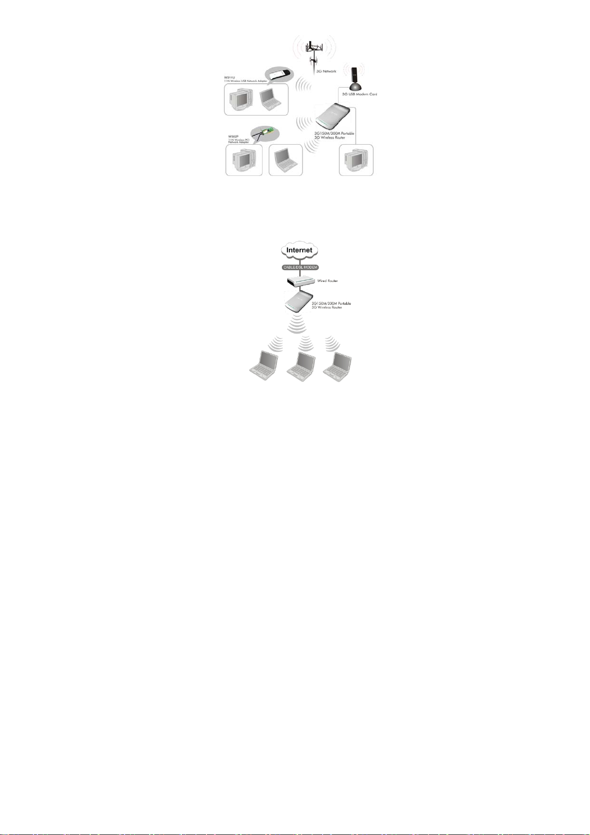
2.2.1 3G Router Mod e
If you have a 3G or 4G wireless broadband USB modem and
service, you can plug the device into the router and share the
connection.
Application: The router can be powered by a laptop USB port to
share internet access in cars, trains, and other mobile or remote
locations.
11
Page 13
2.2.2 Wireless AP Mode
Connect a single Ethernet cable to the access point or let it pick
up another wireless device's transmission, and make a wireless
connection available to all in range.
12
Page 14

2.2.3 WISP Mode
This is mainly used in hotspot access. Not only your computer
can connect to the Internet via a router in WISP mode, but other
Wi-Fi devices (PDA, PSP, Wi-Fi phone) can access the Internet
without running up bills.
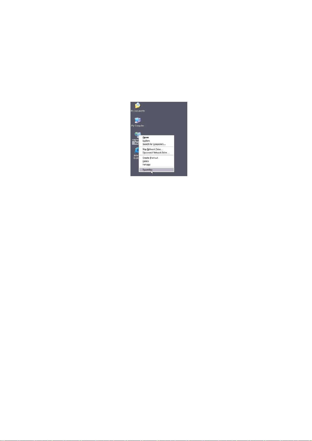
2.2.4 Wireless R outer Mode
Use this mode to form a wireless local network that has broadband
access via an Ethernet cable.
13
Page 15
Chapter 3 How to Login to the Router
The chapter mainly presents how to enter the Router ’s Web page.
After you have finished the hardware installation (Please refer to
chapter2.), the following steps will assist you to set the network
configurations for you computer. The default web page login is
IP:192.168.0.1
3.1 How to Set the Wired Network Configurations
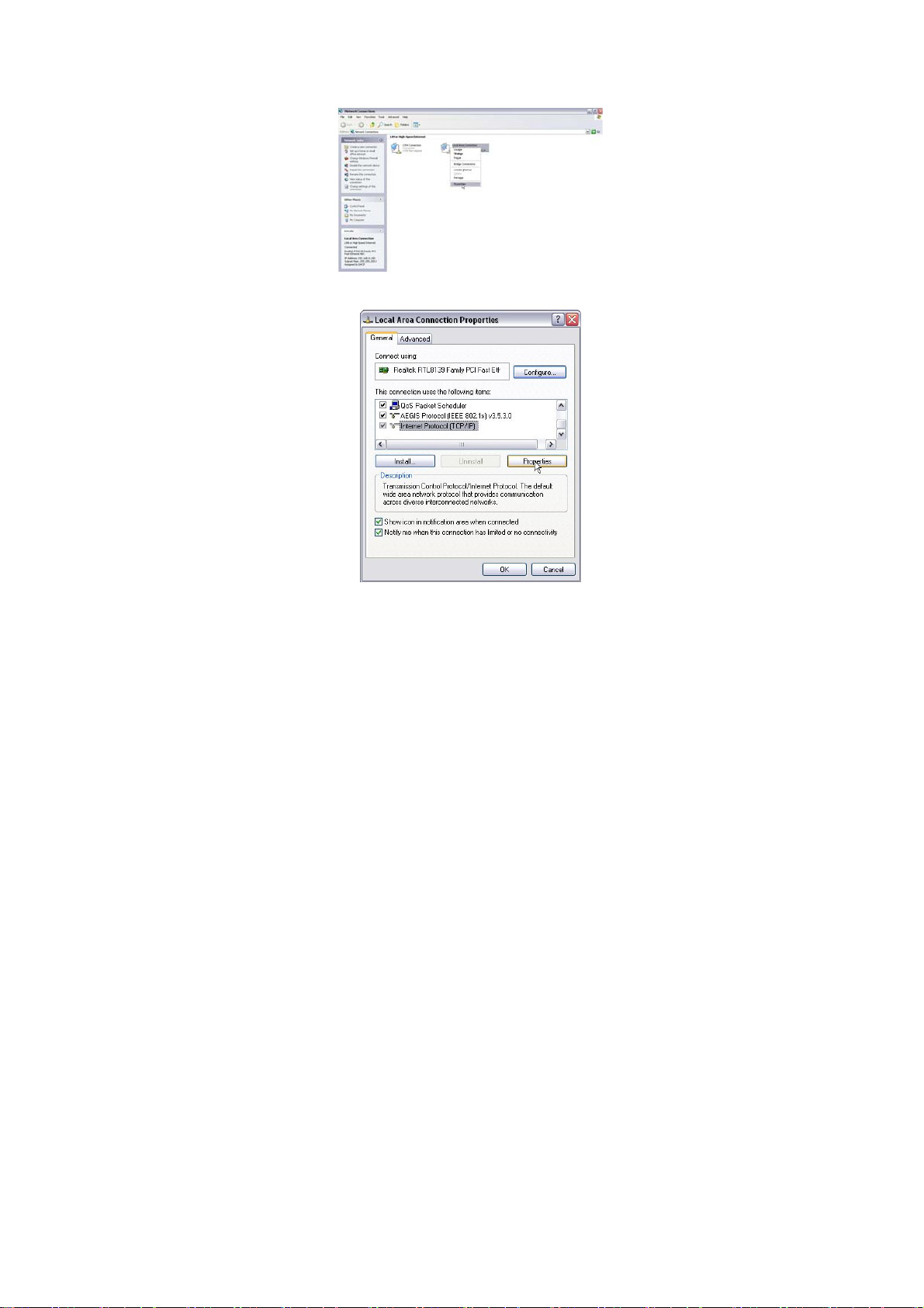
3.1.1 On your computer desktop right click “My Network Places”
and select “Pr op ert ies”.
14
Page 16
3.1.2 Right click “Local Area Network Connection” and select
“Properties”.
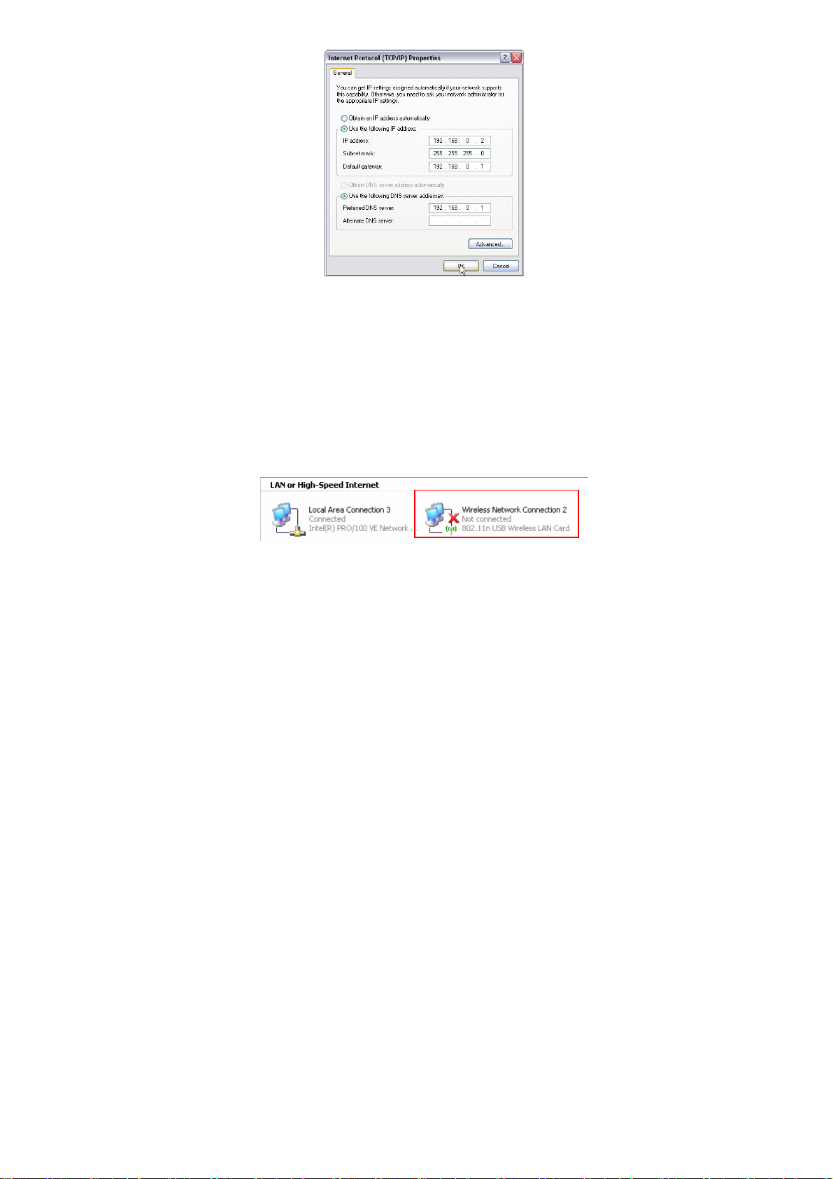
3.1.3 Select “Internet Protocol (TCP/IP)” and click “Properties”.
15
Page 17

3.1.4 Select “Obtain an IP address automatically” or select “Use
the following IP addr ess (S)”.
A. “Obtain an IP address automatically” as the following diagram:
B. “Use the following IP address (S)”
IP Address: 192.168.0.XXX: (XXX is a number from 2~254)
Subnet Mask: 255.255.255.0
Gateway: 192.168.0.1
DNS Server: Certainly you need to input the DNS server address
provided by your ISP. Otherwise, you can use the Router’s default
gateway as the DNS proxy server. Click “OK” to save the
configurations.
16
Page 18
Tip: If you are not sure of the DNS server address, we recommend
you to select “Obtain an IP address automatically (O)” and
“Obtain a DNS server address automatically”.
3.2 How to Set the Wireless Network Connection
If you choose the Wireless Router mode, you should make sure
that you have a wireless network adapter. Then set the wireless
connection as below.
3.2.1 On your computer desktop right click “My Network Places”
and select “Pr op ert ies”.
17
Page 19

3.2.2 Right click “Wireless Network Connection” and select
“Properties” then configure th e IP address as 3.1.3 and 3.1.4.
3.2.3 Right click “Wireless Network Connection” and select
“View Available Wireless Network”. The entire wireless signal will
be shown in the interface. Please select “Tenda”. If you don’t find
it, please click “Refresh Network List”.
3.2.4 Select “Tenda” and click “Connect” or doub le- click “Tenda”
to enter into the Router’ s int erface.
3.3 Login to the Web Interface
After you set you computer as 3.1 and 3.2, you can follow the
below steps to access the Router’s web interface.
18
Page 20
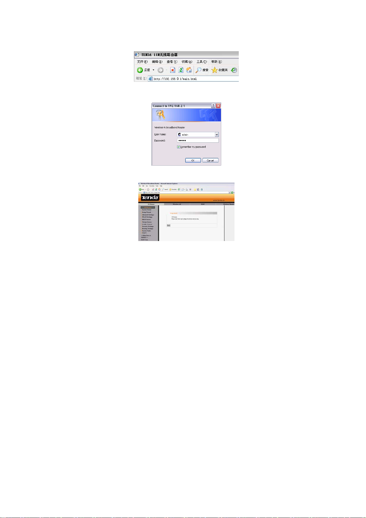
3.3.1 To access the Router’s Web-based interface, l aunch a web
browser such as Internet Explorer and enter the Router’s default
IP addr ess, http: //192.168 .0.1. Press “Enter”.
3.3.2 Input the “admin” in both User Name and Password.
Click “OK”.
3.3.3 If you enter the correct user name and password, the screen
will be the next one.
19
Page 21
Chapter 4 Modes Setup Wizard
There are four working modes: 3G Router, Wireless AP, WISP,
Wireless Router. This chapter will describe the basic settings of
modes using Setup Wizard,
4.1 3G Router Mode
4.1.2 Login to the interface
In “3G Router” mode, click “Setup Wizard” in the left column and
then click “Next”.
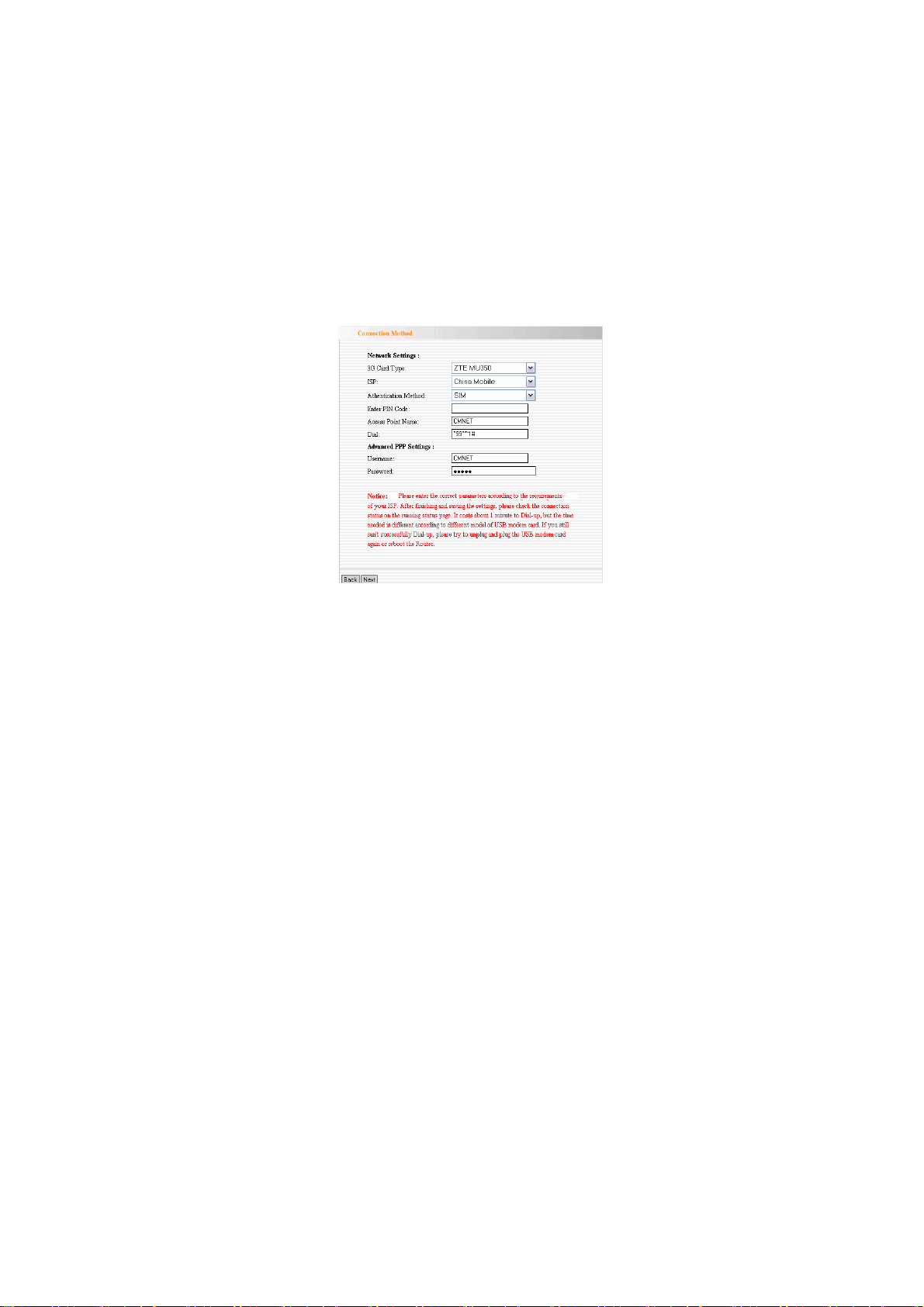
4.1.3Configure the Connetcion Method
First, select your 3G card type.
20
Page 22

Second, select your ISP.
Third, click “Next” to enter Wireless Basic Settings interface.
Tip: If your ISP is not in the list, consult your ISP for detail
parameters and manual input.
4.1.4 Wireless Basic Setting
¾ Network Mode:Select one mode from the following. The
default is 11b/g/n mode.
11b mode: Allow the wireless client to connect with the
device in 11b mode at the maximum speed of 11Mbps.
11g mode: Allow the 11g/11n-compliant client device to
connect with the AP at the maximum speed of 54Mbps.
11b/g mode: Allow the 11b/g-compliant client device to
connect with the AP with auto-negotiation speed, and 11n
wireless client to connect the device with 11g speed.
21
Page 23

11b/g/n mode Allow 11b/g/n-compliant client device to
connect with the AP with auto-negotiation speed.
¾ SSID:SSID (Service Set Identifier) is the unique name of
the wireless network.
¾ Channel:Specify the effective channel (from 1 to 13\Auto)
of the wireless network
¾ Broadcast (SSID): Select “Enable” to enable the device's
SSID to be visible by wireless clients. The default is
enabled.
¾ BSSID:Basic Service Set Identifier of wireless network. In
IEEE802.11, BSSID is the MAC address of wireless access
point.
¾ Extend Channel:To increase data throughput of wireless
network, the extension channel range is used in 11n mode.
¾ Channel Bandwidth: Select the channel bandwidth to
improve the wireless performance. When the network has
11b/g and 11n clients, you can select the 40M; when it is an
11n network, select 20/40M to improve its throughput.
22
Page 24
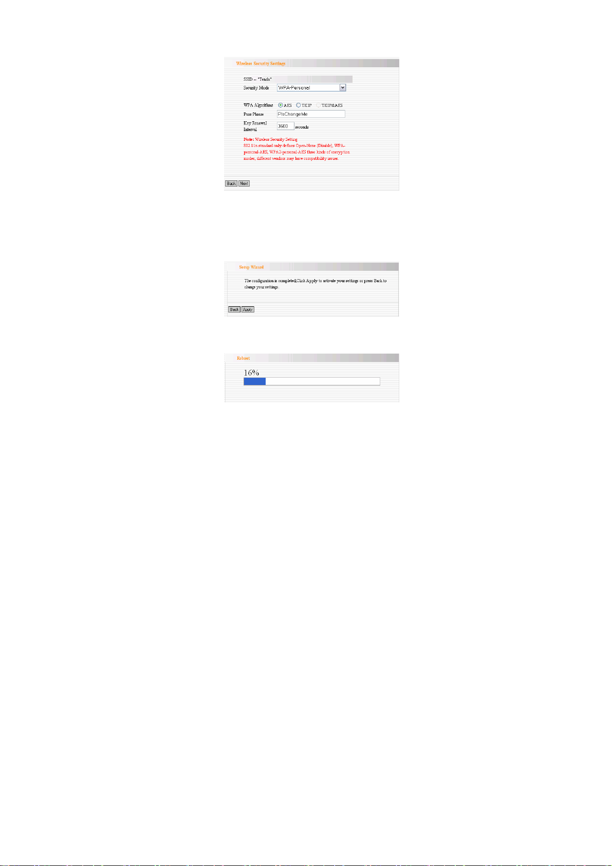
4.1.5 Wireless Security Setting
It is suggested you choose WPA-personal for “Security Mode”
and AES for “WPA Algorithms.” Click “Next” to save the
configuration. More details please refer to the following chapter.
4.1.6 Click “Apply” to save the settings.
The Router is rebooting now, please wait for a few minutes and
DO NOT power off it.
23
Page 25

4.2 Wireless AP Mode
In “Wireless AP”, click “Setup Wizard” in the left column and
then click “Next”. The setting methods please refer to 4.1.4 to
4.1.6.
In this mode, the device is a converter that can convert the
wireless and wired signals. You ca n connect a single Ethernet
cable to the access point or let it pick up another wireless device's
transmission, and make a wireless connection available to all in
range. You can also adjust the connection properties to obtain an
IP address automatically in Internet protocol.
4.3 WISP Mode
If you are provided the wired wan access by your ISP to access the
Internet, you should select WISP mode. Please follow the “Setup
Wizard” to configure the device.
4.3.1 In WISP mode, click “Setup Wizard” in the left column and
then click “Next”.
24
Page 26
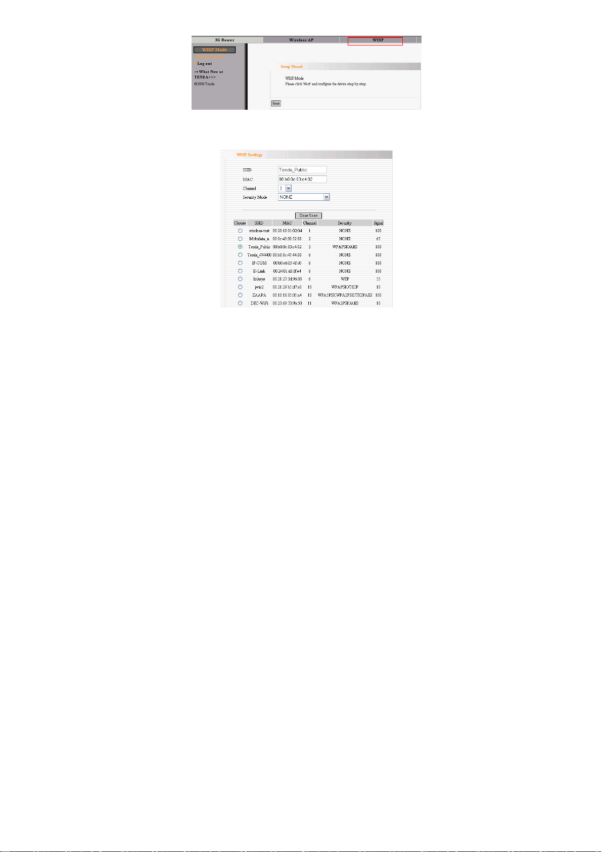
4.3.2 In WISP settings interface, select the channel you want to
use and then click “Scan” to scan the wireless signals.
¾ SSID:SSID (Service Set Identifier) is the unique name of
the wireless network.
¾ MAC Address: The Router’s physical MAC address as seen
on your local network is unchangeable. Input the MAC
address of the AP you want to choose. Sometimes, MAC
25
Page 27
address is also named BSSID. (BSSID:Basic Service Set
Identifier of wireless network. In IEEE802.11, BSSID is the
MAC address of wireless access point.
¾ Channel:Specify the effective channel (from 1 to 13\Auto)
of the wireless network. The channel you select must be
correspondence with the AP provided by your ISP.
¾ Security Mode: The security mode you set should be the
same as the AP. More details please refer to the Wireless
Security Settings chapter.
We recommend you “Scan” the Aps and then select the SSID in
your scanned SSID list for convenience.
Click “Next” to the following interface.
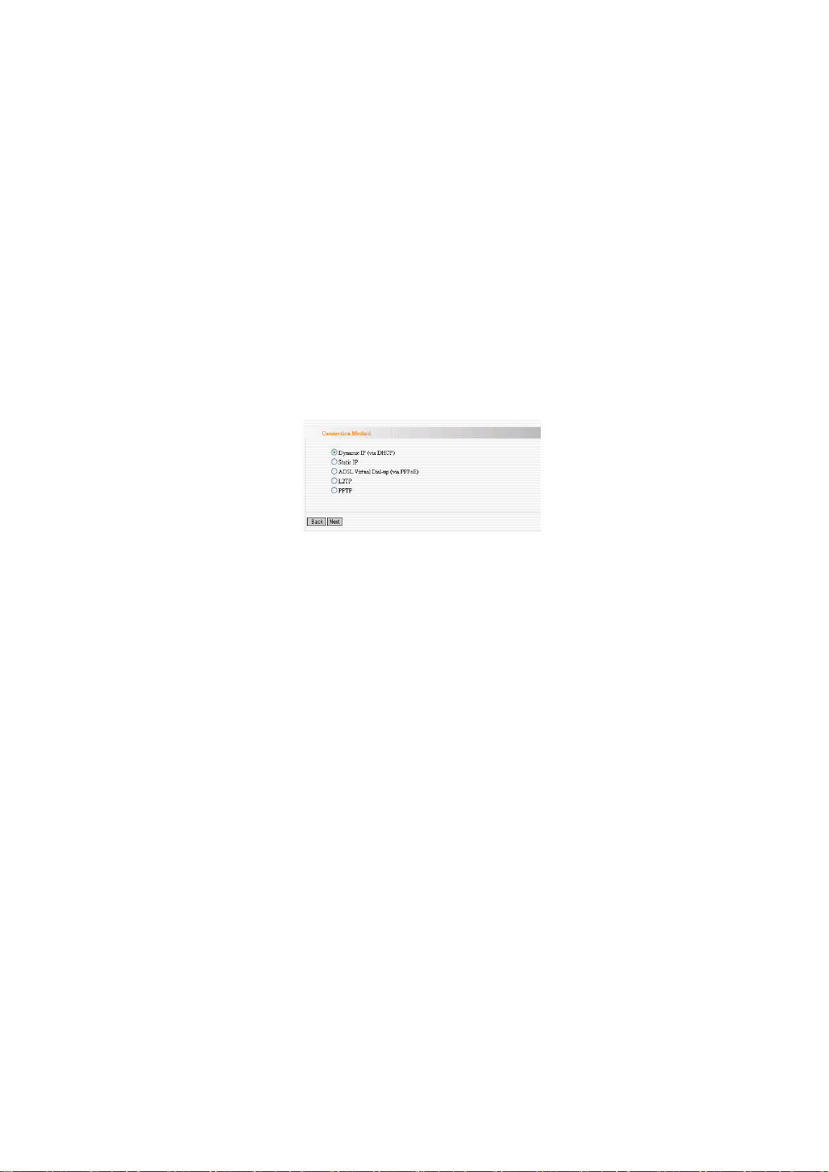
4.3.3 Connection method
In WISP mode, there are three way s of access methods: ADSL
Virtual Dial-up (via PPPoE), Dynamic IP (via DHCP) and Static
IP. It is suggested to choose Dynamic IP and click “Next”. Other
setting methods please refer t o 4.1.4 to 4.1.6.
26
Page 28
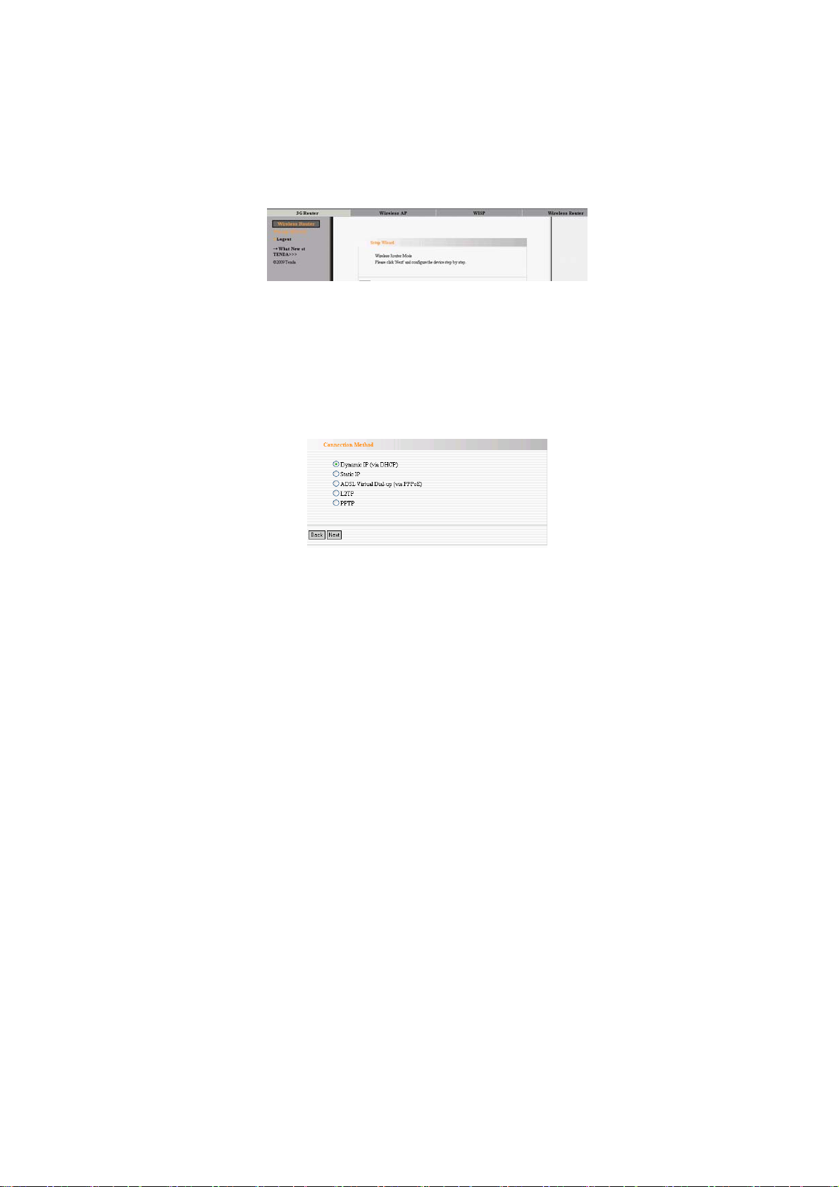
4.4 Wireless Router Mode
In the wireless router mode, you can use this device as the router
directly connected to DSL modem, CABLE modem such
broadband devices or home broadband cable directly
First, login to the interface as chapter 3 described.
4.4.1 Select the “Setup Wizard” in the left column and then click
“Next”.
4.4.2 Configure the “Aceess Meth ods”
a. Dynimic IP(DHCP)
The default access method is DHCP. If your ISP provides you the
Dynamic IP, you can choose DHCP access way. Every time you
access the internet, you will get different IP. Select “Dynamic IP”
and click “Next”. For following steps, please refer to 4.1.4 to
4.1.6.
27
Page 29

b. Static IP
If your ISP provides you the Static IP, please select Static IP
access way. You should input the IP address, Subnet Mask,
Gateway, DNS sever and the secondary DNS sever provided by
your ISP, then click “Next”. Other steps refer to 4.1.4 to 4.1.6.
c. ADSL Virtual Dial-up (via PPPoE)
This way is used when the Router is connected to the wireless
modem or you want to amplify wireless signals and share the
Internet with multiple computers. Enter the Account and Password
provided by your ISP, and click “Next”. If you are not clear,
please contact your ISP.
For example:
If the Account is pppoe_user and Password s 123456, you need to
enter the information as the diagram below. Please enter the
28
Page 30

Account and Password provided by your ISP.
Note: If you choose this access way, the LAN/WAN port is only
worked as the WAN port. The mode will take effect once you set it;
you need to login to the Router’s WEB interface to configure the
device (Details refer to 3.2). After configuration, you should
adjust the connection properties to obtain an IP address
automatically in Internet protocol (details refer to Appendix One).
d . PPTP and L2TP
Configure L2TP and PPTP. Take PPTP as an example.
29
Page 31

PPTP Server: Enter the IP address or PPTP Server domain name
User Name: Enter your PPTP user name
Password: Input your PPTP password
Address Mode: Static mode and Dynamic mode.
Select Dynamic mode to get IP automatically.
If you select Static mode, you need to manually set the IP address,
Subnet Mask, Default Gateway.
30
Page 32

Chapter 5 Advanced Settings
5.1 LAN Setting
This section will describe how to configure the TCP/IP
parameters.
5.1.1 In 3G Router mode, WISP mode, Wireless Router mode,
please configures the LAN port parameters as the below
diagram (Note: In Wireless mode, you can only configure the
device until you using the wireless access way.).
¾ MAC Address: The device’s physical MAC address as
seen on your local network is unchangeable.
¾ IP Address: The Router’s LAN IP addresses
(not your PC’s IP address). 192.168.0.1 is the default value.
¾ Subnet Mask: It’s shown the Router’s subnet mask for
measurement of the network size. 255.255.255.0 is the
default value.
Notice:Once you modify the IP address, you need to remember
31
Page 33

it for the Web-based Utility login next time.
5.1.2 LAN Settings in W ir eless AP Mode
¾ MAC Address: The device’s physical MAC address as
seen on your local network is unchangeable.
¾ IP Mode: There are two modes, Static IP and Dynamic IP.
If you select Static IP, you need to input the parameters
provided by your ISP. If you choose Dynamic IP, you
should adjust the connection properties to obtain an IP
address and DNS sever automatically in Internet protocol.
¾ IP Address: The device’s LAN IP addresses (not your
PC’s IP address). 192.168.0.1 is the default value.
If you change it, you need to use the new IP to login to the Web
interface.
¾ Subnet Mask: It’s shown the device’s subnet mask for
32
Page 34

measurement of the network size. 255.255.255.0 is the
default value.
¾ Default Gateway: Input the Gateway provided by your
ISP. If you are not sure, please consult your ISP.
¾ Primary DNS Sever: Input the primary DNS sever
provided by your ISP.
¾ Secondary DNS Sever: you can input it or empty it. The
parameters are also provided by your ISP
¾ Host Name: The device’s wins name which you can use it
to visit the device.
Notice: once you changed the IP address of the LAN port, you
should use the new IP to enter into the WEB interface.
33
Page 35

5.2 WAN Settings
5.2.1 3G WAN
Network Setting
¾ 3G Card Type: Select you 3G USB Modem card type from
the list.
¾ ISP: Select your ISP.
¾ Apply: Click “Apply” button after configuration.
¾ Cancel: Click “Cancel” to the former settings when you
make a mistake.
¾ Click “System Status” to scan the information. If the
Connection Status of WAN Status shows “Connected”, you
34
Page 36

can share the internet.
Internet Connection Option:
There are four Connection Options: Connect Automatically,
Connect Manually, Connect on Demand, Connect on Fixed Time.
Please select according to your needs.
¾ Connect Automatically: Connect automatically to the
Internet after rebooting the system or connection failure.
¾ Connect Manually: Connect to the Internet by users
manually.
¾ Connect on Demand: Re-establish your connection to the
Internet after the specific time (Max Idle Time). Zero means
your Internet connection at all time. Otherwise, enter the
minutes to be elapsed before you want to disconnect the
Internet access.
¾ Connect on Fixed Time: Connect to the Internet during the
time you fix.
35
Page 37

Note: it is suggested you choosing Connect on Demand without
running up bills, because it can disconnect the internet
automatically when there is no data transmitting or the computer
closed. If you access the internet, it will dial up automatically
which is very convenient.
5.2.2 WAN Settings in WISP Mode and Wireless Router Mode
Depending on your access ways of WAN port, there are three
ways of configuration.
a. Dynamic IP
¾ MTU: Maximum Transmission Unit. It is the size of largest
datagram that can be sent over a network. The default value
is 1492. Do NOT modify it unless necessary. But if some
specific website or web application software can not be open
or enabled, you can have a try to change the MTU value as
1450, 1400, etc.
36
Page 38

b. ADSL Virtual Dial-up(via PPPoE)
¾ Connection Method: It shows the current connection
method.
¾ User Name: Input the user name provided by your ISP.
¾ Password: Enter the password provided by your ISP.
¾ MTU: Maximum Transmission Unit. It is the size of largest
datagram that can be sent over a network. The default value
is 1492. Do NOT modify it unless necessary. But if some
specific website or web application software can not be open
or enabled, you can have a try to change the MTU value as
1450, 1400, etc.
37
Page 39

¾ Service Name: It is defined as a set of characteristics that
are applied to a PPPoE connection. Enter it if provided. Do
NOT modify it unless necessary.
¾ AC Name: Enter it if provided. Do NOT modify it unless
necessary.
¾ Connect Automatically: Connect automatically to the
Internet after rebooting the system or connection failure.
¾ Connect Manually: Connect to the Internet by users
manually.
¾ Connect on Demand: Re-establish your connection to the
Internet after the specific time (Max Idle Time). Zero means
your Internet connection at all time. Otherwise, enter the
minutes to be elapsed before you want to disconnect the
Internet access.
¾ Connect on Fixed Time: Connect to the Internet during the
time you fix.
Notice:
The “Connect on Fixed Time” can be deployed only when you
have set the current time in “Time Settings” from “System Tools”.
38
Page 40

c. Static IP
If your connection mode is static IP, you can modify the following
addressing information.
¾ IP Address: Here enter the WAN IP address provided by
your ISP. If you are not clear, consult you ISP please.
¾ Subnet Mask: Enter the WAN Subnet Mask here.
¾ Gateway: Enter the WAN Gateway here.
¾ Primary DNS Server: Enter the Primary DNS server
provided by your ISP.
¾ Secondary DNS Server: Enter the secondary DNS.
¾ MTU: Maximum Transmission Unit. It is the size of largest
datagram that can be sent over a network. The default value
is 1492. Do NOT modify it unless necessary. But if some
specific website or web application software can not be open
39
Page 41

or enabled, you can have a try to change the MTU value as
1450, 1400, etc.
5.3 MAC Address Clone
This page is for the Router’s MAC address to WAN.(Only in
Wireless Router mode)
Some ISPs require end-user's MAC address to access their
network. This feature copies the MAC address of your network
device to the Router.
¾ MAC Address: The MAC address to be registered with
your Internet service provider.
¾ Clone MAC Address: Register your PC's MAC address.
¾ Restore Default MAC Address: Restore to the default
hardware MAC address.
5.4 DNS Settings
DNS is short for Domain Name System (or Service), an Internet
service that translate domain names into IP addresses which are
40
Page 42

provided by your Internet Service Provider. Please consult your
Internet Service Provider for details if you do not have them.
¾ DNS: Click the checkbox to enable the DNS server. The
Router’s DHCP sever will answer the client’s requests and
distribute DNS address.
¾ Primary DNS Address: Enter the necessary address
provided by your ISP.
¾ Secondary DNS Address: Enter the second address if your
ISP provides, which is optional.
Notice: After the settings are completed, reboot the device to
activate the modified settings.
41
Page 43

Chapter 6 Wireless Setting
6.1 Basic Settings
¾ Enable Wireless: Check to enable the Router’s wireless
features; uncheck to disable it.
¾ Network Mode:Select one mode from the following. The
default is 11b/g/n mode.
11b mode: Allow the wireless client to connect with the
device in 11b mode at the maximum speed of 11Mbps.
42
Page 44

11g mode: Allow the 11g/11n-compliant client device to
connect with the AP at the maximum speed of 54Mbps.
11b/g mode: Allow the 11b/g-compliant client device to
connect with the AP with auto-negotiation speed, and 11n
wireless client to connect the device with 11g speed.
11b/g/n mode:Allow 11b/g/n-compliant client device to
connect with the AP with auto-negotiation speed.
¾ SSID:SSID (Service Set Identifier) is the unique name of
the wireless network. This device has two SSID and the
main SSID is necessary.
¾ Broadcast (SSID): Select “Enable” to enable the device's
SSID to be visible by wirele ss clien ts. The def ault i s ena bled.
If you disable it, the clients must know the SSID to
communicate.
¾ BSSID:Basic Service Set Identifier of wireless network. In
IEEE802.11, BSSID is the MAC address of wireless access
point.
¾ Standard Channel:Specify the effective channel (from 1
to 13\Auto) of the wireless network.
¾ Extension Channel : To increase data throughput of
wireless network, the extension channel range is used in 11n
mode.
43
Page 45

¾ Channel Bandwidth: Select the channel bandwidth to
improve the wireless performance. When the network has
11b/g and 11n clients, you can select the 40M; when it is an
11n network, select 20/40M to improve its throughput.
6.2 Wireless Security Setting
It is used to configure the AP network’s security setting. Here
presents the common six (ten in all) encryption methods,
including WPA-personal, WPA2-personal, Mixed
WAP/WAP2-Personla, Mixed WEP, Open, Shared. It is suggested
you choose WPA-personal for “Security Mode” and AES for
“WPA Algorithms.” Please note that all connecting wireless
devices will need to match these security settings in their
connection settings. More details please refer to the Appendix Two.
In this section, three common encryption methods are introduced.
6.2.1 WP A-Personal
WPA (Wi-Fi Protected Access), a Wi-Fi standard, is a more recent
wireless encryption scheme, designed to improve the security
features of WEP. It applies more powerful encryption types (such
as TKIP [Temporal Key Integrity Protocol] or AES [Advanced
Encryption Standard]) and can change the keys dynamically on
every authorized wireless device.
44
Page 46

¾ WPA Algorithms:Provides TKIP [Temporal Key Integrity
Protocol] or AES [Advanced Encryption Standard].
¾ Pass Phrase: Enter the encrypted characters with 8-63
ASCII characters.
¾ Key Renewal Interval:Set the key’s renewal period.
6.2.2 WP A2- Personal
WPA2 (Wi-Fi Protected Access version 2) provides higher
security than WEP (Wireless Equivalent Privacy) or WPA (Wi-Fi
Protected Access). Besides TKIP encryption, new AES encryption
mode is provided.
45
Page 47

¾ WPA Algorithms:Provides TKIP [Temporal Key Integrity
Protocol], AES [Advanced Encryption Standard] or
TKIP&AES mixed mode.
¾ Pass Phrase:Enter the encrypted characters with 8-63
ASCII characters.
¾ Key Renewal Interval:Set the key’s renewal period.
6.2.3 Mixed WEP
WEP (Wired Equivalent Privacy), a basic encryption method,
usually encrypts wireless data using a series of digital keys (64 bits
or 128 bits in length). By using the same keys on each of your
wireless network devices, you can prevent unauthorized wireless
devices from monitoring your transmissions or using your wireless
resources. Select Mixed WEP to enter the following window:
46
Page 48

¾ Select SSID:Select the SSID (main SSID or minor SSID)
to configure security setting from the drop-down menu.
¾ Security Mode:From the drop-down menu select the
corresponding security encryption modes.
¾ WEP Key:Set the WEP key with the format of ASCII and
Hex.
¾ Key Explanation: You can enter ASCII code (5 or 13
ASCII characters. Illegal character as “/” is not allowed.) Or
10/26 hex characters.
¾ Default Key:Select one key from the four configured keys
as the current available
47
Page 49

6.3 Advanced Settings
This section is to configure the advanced wireless setting of the
Router, including the BG Protection Mode, Basic Data Rates,
Fragmentation Threshold, RTS Threshold, and WMM etc.
¾ BG protection Mode: Auto by default. It is for 11b/g
wireless client to connect 11n wireless network smoothly in
a complicated wireless area.
¾ Basic Data Rates: For different requirement, you can select
one of the suitable Basic Data Rates. Here, default value is
(1-2-5.5.-11Mbps…). It is recommended not to modify this
value.
¾ Beacon Interval: Set the beacon interval of wireless radio.
Default value is 100. It is recommended not to modify this
value.
¾ Fragment Threshold: The fragmentation threshold defines
48
Page 50

the maximum transmission packet size in bytes. The packet
will be fragmented if the arrival is bigger than the threshold
setting. The default size is 2346 bytes. It is recommended
not to modify this value.
¾ RTS Threshold: RTS stands for “Request to Send”. This
parameter controls what size data packet the frequency
protocol issues to RTS packet. The default value of the
attribute is 2346. It is recommended not to modify this value
in SOHO environment.
¾ TX Power: Set the output power of wireless radio. The
default value is 100.
¾ WMM Capable: It will enhance the data transfer
performance of multimedia data when they’re being
transferred over wireless network. It is recommended to
enable this option.
¾ APSD Capable: It is used for auto power-saved service.
The default is disabled.
6.4 WPS Settings
WPS (Wi-Fi Protected Setting) can be easy and quick to establish
the connection between the wireless network clients and the
device through encrypted contents. The users only enter PIN code
or press WPS button on the panel to configure it without selecting
49
Page 51

encryption method and secret keys by manual. In the “WLAN
settings” menu, click “WPS settings” to enter the next screen.
¾ WPS settings:To enable or disable WPS function. The
default is “disable”.
¾ WPS mode : Provide two ways: PBC (Push-Button
Configuration) and PIN code.
¾ PBC:Select the PBC or press the WPS button on the back
panel of the device for about one second (Press the button
for about one second and WPS indicator will be blinking for
2 minutes, which means the WPS is enabled. During the
blinking time, you can enable another device to implement
the WPS/PBC negotiation between them. Two minutes later,
50
Page 52

the WPS indicator will be off, which means the WPS
connection is completed. If more clients are added, repeat
the above steps. At present, the WPS supports up to 32
clients access.)
¾ PIN:If this option is enabled, you need to enter a wireless
client’s PIN code in the field and keep the same code in the
WPS client.
¾ WPS Summary : Show the current state of Wi-Fi
protected setting, including authorized mode, encryption
type, default key and other information.
¾ WPS Current Status:Idle means WPS in idle state. Start
MSC process means the process has been started and waits
for being connected. Configured means the negotiation is
successful between server and clients.
¾ WPS Configured: “yes” means WPS feature is enabled
and goes into effect. “Not used” means it is not used.
Usually the AP-security has been enabled, here will
displayed “not used”.
¾ WPS SSID: Show the main SSID set by WPS.
¾ WPS Auth. Mode:The authorization mode deployed by
WPS, generally WPA/WPA2-personal mode.
¾ WPS Encrypt Type:The encryption type used by WPS,
51
Page 53

generally AES/TKIP .
¾ WPS key : The effective key generated by AP
automatically.
¾ AP PIN(KEY):The PIN code used by default.
¾ Reset OOB: When this button is pressed, the WPS client
will be idle state, and WPS indicator will be turned off. AP
will not respond the WPS client’s requests and the set the
security mode as WPA mode.
6.5 Wireless Access Control
To secure your wireless LAN, the wireless access control is
actually based on the MAC address management to allow or block
the specific clients to access the wire less network. Sele ct “WLAN
Setting->Access Control” to display the following screen:
¾ MAC Address Filter:Allow/Block MAC address filter.
Select “off” to malfunction MAC address; “Block” to
52
Page 54

prevent the MAC addresses in the list from accessing the
wireless network; “Allow” to allow the MAC address in the
list to access the wireless network.
¾ MAC Address Management:Input the MAC address to
implement the filter policy. Click “Add” to finish the MAC
add operation.
¾ MAC Address list:Show the added MAC addresses. You
can add or delete them.
6.6 Connection Status
This page shows wireless client’s connection status, including
MAC address, Channel bandwidth, etc. Select “WLAN
Setting->connection status” to enter the following screen:
¾ MAC Address:Shows current MAC addresses of the hosts
connecting to the Router.
¾ Bandwidth : Shows current frequency bandwidth the
wireless client used.
53
Page 55

Chapter 7 DHCP Server
DHCP server is for the 3G Router, signal amplification and
wireless Router mode.
7.1 DHCP Settings
DHCP (Dynamic Host Control Protocol) is to assign an IP address
to the computers on the LAN/private network. When you enable
the DHCP Server, the DHCP Server will allocate automatically an
unused IP address from the IP address pool to the requesting
computer in premise of activating “Obtain an IP Address
Automatically”. So specifying the starting and ending address of
the IP Address pool is needed.
¾ DHCP Server: Activate the checkbox to enable DHCP server.
¾ IP Address Start: Enter the range of IP address pool for
DHCP server distribution.
¾ IP Address End: Enter the range of IP address pool for DHCP
server distribution.
¾ Lease Time: The length of the IP address lease.
54
Page 56

For example:
If the lease time is an hour, then DHCP server will reclaim the IP
address each hour.
7.2 DHCP List and Binding
DHCP client can display computers’ IP address; MAC address,
host name and other information which are assigned by the DHCP
sever. You can manually enter the IP and MAC address; it would
be converted to static allocation. According to the computer's
MAC address, DHCP will assign the appropriate IP address. If
you can not find the corresponding static binding entry, assign a IP
from the DHCP pool to the computer. If the computer had been
bound for the IP address and MAC and they do not correspond,
then the computer will be unable to access equipment. (Through
binding prevents unauthorized to change the client IP address and
to evade the monitoring device)
55
Page 57

¾ IP Address: Enter the IP address which needs to be bound.
¾ MAC Address: Enter the MAC address of the computer
you want to assign the above IP address. Click “Add” to add
the entry in the list.
¾ Hostname: The name of the computer which is added a new
IP address.
¾ Lease Time: The left time length of the corresponding IP
address lease.
56
Page 58

Chapter 8 Virtual Server
Virtual Server feature is only for wireless signal amplification
mode and the wireless Router mode.
8.1 Port Range Forwarding
This section deals with the port range forwarding mainly. The Port
Range Forwarding allows you to set up a range of public services
such as web servers, ftp, e-mail and other specialized Internet
applications to an assigned IP address on your LAN.
¾ Start/End Port: Enter the start/end port number which
ranges the External ports used to set the server or Internet
applications.
¾ IP Address: Enter the IP address of the PC where you want
57
Page 59

to set the applications.
¾ Protocol: Select the protocol (TCP/UDP/Both) for the
application.
¾ Enable: Click to check it for corresponding operation.
¾ Delete: Click to empty the parameters.
¾ Well-Known Service Port: Select the well-known services
as DNS, FTP from the drop-down menu to add to the
configured one above.
¾ Add: Add the selected well-known port to the policy ID.
For example:
The server at the IP address of 192.168.0.10 in LAN provides
WEB service at the port of 80 and Telnet service at the port of 23.
If you want the clients on the Internet to visit this server, please set
the device as the diagram above.
NOTE: If you set the virtual server of the service port as 80, you
must set the Web management port on Remote Web Management
page to be any value except 80 such as 8080. Otherwise, there will
be a conflict to disable the virtual server.
8.2 DMZ Settings
The DMZ function is to allow one computer in LAN to be
exposed to the Internet for a special-purpose service as Internet
gaming or videoconferencing.
58
Page 60

¾ DMZ Host IP Address: The IP address of the computer you
want to expose.
¾ Enable: Click the checkbox to enable the DMZ host.
For example:
Set the computer at the IP address of 192.168.0.100 in LAN as a
DMZ Host to intercommunicate with another host on the Internet.
IMPORTANT:
When the DMZ host is enabled, the firewall settings of the DMZ
host will not function.
8.3 UPNP Settings
It supports latest Universal Plug and Play. This function goes into
effect on Windows XP or Windows ME or this function would go
into effect if you have installed software that supports UPnP. With
the UPnP function, host in LAN can request the router to process
some special port switching so as to enable host outside to visit
the resources in the internal host.
59
Page 61

¾ Enable UPnP: Click the checkbox to enable the UPnP.
60
Page 62

Chapter 9 Traffic Control
Traffic control is used to limit communication speed in the LAN
and WAN. Up to 20 entries can be supported with the capability
for at most 254 PCs' speed control, including for IP address range
configuration.
¾ Enable Traffic Control: To enable or disable the internal IP
bandwidth control. The default is disabled.
¾ Interface: To limit the uploading and downloading
bandwidth in WAN port.
¾ Service: To select the controlled service type, such as HTTP
service.
¾ IP Address:The range of IP addresses, it can be a single IP
61
Page 63

or IP segment.
¾ UP/Down: To specify the traffic heading way for the
selected IP addresses: uploading or downloading.
¾ Bandwidth Range: To specify the uploading/downloading
Min. /Max. Traffic speed (KB/s), which can not exceed the
WAN speed.
¾ Apply: To enable the current editing rule. If not, the rule
will be disabled.
¾ Add: After edit the rule, click the “add to list” button to add
the current rule to rule list.
¾ Apply: Click “Save” to activate the current rule.
¾ Cancel: Click “Cancel” to drop all setting saved last time.
62
Page 64

Chapter 10 3G WAN Traffic and Connection Timer
10.1 3G WAN T raffic
In 3G WAN mode, 3G WAN traffic function is supported. Click
"3G WAN traffic" you can check the router's Internet traffic,
transmission rate, transmission data volume and traffic for nearly
two months, so that you can know how much the traffic that the
3G modem card accesses the Internet without running up bills.
Notice: this function is only for 3G WAN.
In 3G Router mode, 3G WAN traffic is used to calculate the
traffics of WAN port. Click “3G WAN Traffic” then you can
inquiry the status such as the status
10.2 Connection Timer
In 3GWAN mode, Connection Timer function is supported. Click
“System Status" then you can see the WAN port connection time,
internet access time of this month and other status.
63
Page 65

Note:The result of 3G WAN Traffic and Connection Timer are
only for reference. This device can only calculate the status that
the 3G modem card plugs into the device. The actual statistics is
subject to the ISP.
64
Page 66

Chapter 11 Security Settings
The security settings are for the 3G Router, the Wireless signal
amplification mode and the Wireless Router mode. The security
settings of wireless access point (AP) mode please refer to
Chapter 6.
11.1 Client Filter Settings
To benefit your further management to the computers in the LAN,
you can control some ports access to Internet by data packet filters
function.
¾ Client Filter: Check to enable client filter.
65
Page 67

¾ Access Policy: Select one number from the drop-down
menu.
¾ Enable: Check to enable the access policy.
¾ Filter Mode: Click one radio button to enable or disable to
access the Internet.
¾ Policy Name: Enter a name for the access policy selected.
¾ IP Start/End: Enter the starting/ending IP address.
¾ Port: Enter the port range based over the protocol for access
policy.
¾ Type: Select one protocol (TCP/UDP/Both) from the
drop-down menu.
¾ Times: Select the time range of client filter.
¾ Days: Select the day(s) to run the access policy.
For example:
If you don’t want the computer at the IP address of 192.168.0.100
to access the Internet from 9:00 to 18:00 everyday without
restrictions to other computers in LAN, you need to set the packet
filtering list as the above diagram.
11.2 URL Filter Settings
In order to control the computer to have access to websites, you
can use URL filtering to allow the computer to have access to
certain websites at fixed time and forbids it having access to
66
Page 68

certain websites at fixed time.
¾ URL Filter: Check to enable URL filter.
¾ Access Policy: Select one number from the drop-down
menu.
¾ Enable: Check to enable the access policy.
¾ Filter Mode: Click one radio button to enable or disable to
access the Internet.
¾ Policy Name: Enter a name for the access policy selected.
¾ Start/End IP: Enter the starting/ending IP address.
¾ URL: Specify the text strings or keywords needed to be
filtered. If any part of the URL contains these strings or
words, the web page will not be accessible and displayed.
¾ Times: Select the time range of client filter.
67
Page 69

¾ Days: Select the day(s) to run the access policy.
¾ Apply: Select Apply to enable the settings.
For example:
If you want the computer at the IP address of 192.168.0.123 to
access the Internet from 9:00 to 18:00 everyday and only can
search the WEB pages contain the strings such as sina, sohu, and
yahoo, you need to set the packet filtering list as the above
diagram. (Notice: different strings need to be aparted by a
comma.)
11.3 MAC Address Filter
In order to manage the computers in LAN better, you could
control the computer’s access to Internet by MAC Address Filter.
68
Page 70

¾ MAC Address Filter: Check to enable MAC address filter.
¾ Access Policy: Select one number from the drop-down
menu.
¾ Enable: Check to enable the access policy.
¾ Filter Mode: Click one radio button to enable or disable to
access the Internet.
¾ Policy Name: Enter a name for the access policy selected.
¾ MAC Address: Enter the MAC address you want to run the
access policy.
¾ Times: Select the time range of client filter.
¾ Days: Select the day(s) to run the access policy.
¾ Apply: Select Apply to enable the settings.
For example:
If you want to configure the host with MAC address
00:22:15:55:2A:15 not to access the Internet at 9:00-18:00,
you need to set it as above.
11.4 Prevent Network Attack
This section is to protect the internal network from exotic attack
such as SYN Flooding attack, Smurf attack, LAND attack, etc.
Once detecting the unknown attack, the Router will restrict its
bandwidth automatically.
The attacker’s IP address can be found from the “System Log”.
69
Page 71

¾ Prevent Network Attack: Check to enable it for attack
prevention.
11. 5 Remote Web Management
This section is to allow the network administrator to manage the
Router remotely. If you want to access the Router from outside the
local network, please select the “Enable”.
¾ Enable: Check to enable remote web management.
¾ Port: The management port open to outside access. The
default value is 80.
¾ WAN IP Address: Specify the range of the WAN IP address
for remote management.
70
Page 72

:
1. If you want to login the device’s Web-based interface via
Note
port 8080, you need use the format of WAN IP address: port (for
example http
2. If your WAN IP address starts and ends with 0.0.0.0, it means
all hosts in WAN can implement remote Web management. If you
change the WAN IP address as 218.88.93.33-218.88.93.35, then
only the IP addresses as 218.88.93.33, 218.88.93.34 and
218.88.93.35 can access the Router.
For example:
If you want to configure the IP address 218.88.93.33 to access the
device’s web interface, please set it as above.
11.6 WAN Ping
The ping test is to check the status of your internet connection.
When disabling the test, the system will ignore the ping test from
WAN.
:
//220.135.211.56:8080) to implement remote login.
¾ Ignore the Ping from WAN:
Check to ignore the ping request and give no reply.
71
Page 73

Chapter 12 Routing Setting
Routing Table
The main duty for a router is to look for a best path for every data
frame, and transfer this data frame to a destination. So, it’s
essential for the router to choose the best path, i.e. routing
arithmetic. In order to finish this function, many transferring paths,
i.e. routing table, are saved in the router, for choosing when
needed.
72
Page 74

Chapter 13 System Tools
13.1 Time Settings
This section is to select the time zone for your location. If you turn
off the Router, the settings for time disappear. However, the
Router will automatically obtain the GMT time again once it has
access to the Internet.
¾ Time Zone: Select your time zone from the drop-down
menu.
¾ Customized time: Enter the time you customize.
:
Note
When the Router is powered off, the time setting will be lost.
Before the Router will obtain GMT time automatically, you need
connect with the Internet and obtain the GMT time, or set the time
on this page first. Then the time in other features (e.g. firewall)
can be activated.
73
Page 75

13.2 DDNS
The DDNS (Dynamic Domain Name System) is supported in this
Router. It is to assign a fixed host and domain name to a dynamic
Internet IP address, which is used to monitor hosting website, FTP
server and so on behind the Router. If you want to activate this
function, please select “Enable” and a DDNS service provider to
sign up.
¾ Main Features:
Owing to ISP most times provides dynamic IP address,
DDNS is used to capture the changeable IP address and
match the fixed domain. Then users can have access to the
Internet to communicate with others.
DDNS can help you establish virtual host in your home and
company.
¾ DDNS: Click the radio button to enable or disable the
DDNS service.
74
Page 76

¾ Service Provider: Select one from the drop-down menu and
press “Sign up” for registration.
¾ User Name: Enter the user name the same as the
registration name.
¾ Password: Enter the password you set.
¾ Domain Name: Enter the domain name which is optional.
For example:
In the local host 192.168.0.10 establish a Web server, and register
in 3322.org as follows:
User name tenda
Password 123456
Domain Name tenda.vicp.net
After mapping the port in the virtual server, setting account
information in DDNS server and in the address field entering
http://tenda.3322.org, you can access the Web page.
13.3 Backup/Restore Settings
The device provides backup/restore settings, so you need set a
directory to keep these parameters.
75
Page 77

¾ Backup Setting:
Click “Backup” button to back up the Router’s settings and
select the path for save.
Click “Save” to save the configuration files.
76
Page 78

¾ Restore Setting:
Click “Browse” button to select the backup files.
Click “Restore” button to restore previous settings.
14.4 Restore to Factory Default Setting
This button is to reset all settings to the default values. It means
the Router will lose all the settings you have set. So please Note
down the related settings if necessary.
77
Page 79

¾ Restore: Click this button to restore to default settings.
¾ Factory Default Settings:
User Name: admin
Password: admin
IP Address: 192.168.0.1
Subnet Mask: 255.255.255.0
NOTE: After restoring to default settings, please restart the
device, then the default settings can go into effect.
13.5 Upgrade Firmware
The Router provides the firmware upgrade by clicking the
“Upgrade” after browsing the firmware upgrade packet which you
can download from www.tenda.cn
.
78
Page 80

¾ Browse: click this button to select the upgrade file.
¾ Upgrade: click this button to start the upgrading process.
After the upgrade is completed, the Router will reboot
automatically.
Note: Do not disconnect the device during the upgrade.
13.6 Reboot the Router
Rebooting the Router makes the settings configured go into effect
or to set the Router again if setting failure happens.
Reboot the router: Click this button to reboot the device.
13.7 Password Change
This section is to set a new user name and password to better
secure your router and network.
79
Page 81

¾ User Name: Enter a new user name for the device.
¾ Old Password: Enter the old password.
¾ New Password: Enter a new password.
¾ Re-enter to Confirm: Re-enter to confirm the new
password.
Note: It is highly recommended to change the password to secure
your network and the Router.
13.8 System Log
The section is to view the system log. Click the “Refresh” to
update the log. Click “Clear” to clear all shown information. If the
log is over 150 records, it will clear them automatically.
80
Page 82

¾ Refresh: Click this button to update the log.
¾ Clear: Click this button to clear the current shown log.
13.9 Logout
After you have finished the settings completely, in logout page
click “Yes” to logout the web management page.
81
Page 83

Appendix :Ⅰ How to “Obtain an IP Automatically”
If you enable DHCP (default), you can get the IP address,
Gateway, DNS automatically to access the internet. Please set you
device as below.
1. On your computer desktop right click “My Network Places”
and select “Properties”.
2. Right click “Local Area Network Connection” and select
“Properties”. If you use wireless connection, please click
“Wireless Network Connection”.
82
Page 84

3. Select “Internet Protocol (TCP/IP)” and click “Properties”.
83
Page 85

4. Select “Obtain an IP address automatically”
5. Select “Status” within “Local Area Connection " – click
"support "dialog box, you can see whether you have got the IP.
84
Page 86

Appendix Ⅱ: How to set the network adapter after
device encrypted
When the device is encrypted, you need to enter password to
connect to the wireless device to access the internet. Set up a
wireless network adapter as follows:
1. On your computer desktop right click “My Network Places”
and select “Properties”.
2. Right click “Wireless Network Connection” and select “View
Available Wireless Network”. The entire wireless signal will be
shown in the interface. Please select “Tenda”. If you don’t find it,
please click “Refresh Network List”.
85
Page 87

3. Select “Tenda” and click “Connect” or double-click “Tenda”,
input the “Network key” and “Confirm network key” to connect
the Router
4. “Connected” will be shown in the interface as the following
diagram.
86
Page 88

Appendix GlossaryⅢ
3G
3G, the 3rd Generation, refers to the third digital communication
technology. It can manage multi-media such as image, audio, and
video streams etc. and provide different communication services
such as web browse, telephone session, and electronic business
etc.
CDMA2000
CDMA2000, also called CDMA Multi-Carrier, is one of the
current three 3G standards in the world which was put forward by
an American company. The system derives from narrow frequency
CDMAOne digital standard. You can upgrade the original
CDMAOne structure to 3G with cheap construction cost.
WCDMA
WCDMA (Wideband CDMA), also called CDMA Direct Spread,
is the broadband CDMA technology which was put forward by
Europe. It is the standard of 3G technology which was developed
from GSM network. The standard has put forward the evolved
strategy. The system can be established on the present GSM
network. The system provider can change into this system easily
and it would be accepted widely in Asia. Thus, W-CDMA has a
born advantage in market and is one of the three 3G standards in
87
Page 89

the world.
Channel
An instance of medium use for the purpose of passing protocol
data units (PDUs) that may be used simultaneously, in the same
volume of space, with other instances of medium use(on other
channels) by other instances of the same physical layer
(PHY),with an acceptably low frame error ratio(FER) due to
mutual interference.
SSID
Service Set Identifier .An SSID is the network name shared by all
devices in a wireless network. Your network’s SSID should be
unique to your network and identical for all devices within the
network. It is case-sensitive and must not exceed 20 characters
(use any of the characters on the keyboard).Make sure this setting
is the same for all devices in your wireless network.
WEP
Wired Equivalent Privacy (WEP) is the method for secure
wireless data transmission. WEP adds data encryption to every
single packet transmitted in the wireless network. The 40bit and
64bit encryption are the same because of out 64 bits, 40 bits are
private. Conversely, 104 and 128 bit are the same. WEP uses a
common KEY to encode the data. Therefore, all devices on a
wireless network must use the same key and same type of
88
Page 90

encryption. There are 2 methods for entering the KEY; one is to
enter a 16-bit HEX digit. Using this method, users must enter a
10-digit number (for 64-bit) or 26-digit number (for 128-bit) in the
KEY field. Users must select the same key number for all
devices. The other method is to enter a text and let the computer
generate the WEP key for you. However, since each product use
different method for key generation, it might not work for
different products. Therefore, it is NOT recommended using.
WPA/WPA2
A security protocol for wireless networks that builds on the basic
foundations of WEP. It secures wireless data transmission by
using a key similar to WEP, but the added strength of WPA is that
the key changes dynamically. The changing key makes it much
more difficult for a hacker to learn the key and gain access to the
network.WPA2 is the second generation of WPA security and
provides a stronger encryption mechanism through Advanced
Encryption Standard (AES), which is a requirement for some
government users.
89
Page 91

Appendix : TroubleshootingⅣ
In this part some questions and problems shown during the
Router’s usage and installation will be given suggesting answers.
If your problems are not in the list, please log into our website
www.tenda.cn or send an E-mail to support@tenda.cn, and we
will reply you in the earliest time.
1. Enter the IP address but can not visit the WEB management
interface. What can I do?
Please make sure the cable is well connected and the
corresponding indicator is light.
Make sure the device is not in Wireless Router mode. In this mode,
you can visit the WEB interface only by Wireless network.
In the wireless access point (AP) mode, your computer must
specify an IP (192.168.0.2 ~ 192.168.0.254) to access the device.
Please click
“Start" - " Run "to enter “ping 192.168.0.1”to diagnose whether the
device is connected. If it can ping pass, then check whether your
browser enable a proxy server. If enabled please disable it. If you can
not ping pass, you can hold down the "RESET" button for 7 seconds
to restore the factory settings, and “ping192.168.0.1” again.
2. Forget the login password and can not enter the setting page.
What can I do?
Press the “RESET” button for 7 seconds to restore the Router to
90
Page 92

default settings.
3. The computer connected with the Router shows IP address
conflict. What can I do?
Check if there are other DHCP servers in the LAN. If there have,
disable them.
The default IP address of the Router is 192.168.0.1 and please
maker sure the address is not occupied by other devices. If there
are two computers with the same IP addresses, please modify one.
4. My computer can not log in equipment; can not access the
internet, and a yellow triangle with exclamation point symbols
shows, how to deal with?
This problem is due to your network card is not assigned the IP
address. If set your computer to automatically obtain IP, please
ensure that the source of the router's DHCP is turned on. DHCP
can automatically assign an IP address to your computer. If there
is no DHCP, please set a static IP address and fill in gateways and
DNS, otherwise you can not access Internet.
5. I can not use E-mail and access the Internet. What can I do?
It happens in ADSL connection and Dynamic IP users. And you
need modify the default MTU value (1492). Please in the “WAN
Setting” modify the MTU value with the recommended value as
1450 or 1400.
6. How can I configure and access the Internet via Dynamic
91
Page 93

IP?
In Setup Wizard of the Web utility interface, select “Dynamic IP”
connection type and click “Save” to activate it. As some ISPs bind
the user computer’s MAC address, you need to cl one the Router ’s
WAN MAC address to the bind21ing PC’s MAC address. Select
“MAC Address Clone” in “Advanced Setting” to input your
computer’s MAC address and click “Apply” to activate it.
7. How to share my computer’s source with other users in
Internet?
If you want Internet users to access the internal server via the
Router such as e-mail server, Web, FTP, you can configure the
“Virtual Server” to come true.
Step 1: create your internal server, make sure the LAN users can
access these servers and know related service port. For example,
Web server’s port is 80; FTP is 21; SMTP is 25 and POP3 is 110.
Step 2: in the Router’s web click “Virtual Server” and select
“Single Port Forwarding”.
Step 3: input the external service port given by the Router, for
example, 80.
Step 4: input the internal Web service port, for example, 80.
Step 5: Input the internal server’s IP address. If your Web server’s
IP address is 192.168.0.10, please input it.
Step 6: select the communication protocol used by your internal
92
Page 94

host: TCP, UDP, ICMP .
Step 7: click “Apply” to activate the settings.
The following table has listed the well-known application and
service port:
Server Protocol Service Port
WEB Server TCP 80
FTP Server TCP 21
Telnet TCP 23
NetMeeting TCP
MSN Messenger TCP/UDP
PPTP VPN TCP 1723
Iphone5.0 TCP 22555
SMTP TCP 25
POP3 TCP 110
8. Why can’t I use wireless WAN function to access the
Internet?
a. Please make sure that the wireless adapter can access the
Internet when connected to the computer, wireless signals
scanned by the adapter are strong enough, and quality of signals
is good enough. If it can scan too many wireless signals, we
recommend you to use 11b/g mode for reducing interference.
93
1503、1720
File Send:6891-6900(TCP)
Voice:1863、6901(TCP)
Voice:1863、5190(UDP)
Page 95

b. Please make sure that the needed parameters such as SSID,
MAC address etc. are correct. It is recommended to use Auto
Scan to finish the settings in the setup process.
c. Please make sure that IP address range obtained at WAN port
are different as the one obtained at LAN port. If they are at the
same range, you can modify the LAN IP address to solve the
problem.
d. Please do not detach any antenna of the wireless
Router when you are using the Router.
After trying all the above steps, if you still can’t access the
Internet, you can contact us for support.
94
Page 96

Appendix :Ⅴ Complied 3G Modem Card List
Brand Model Brand Model
Tenda 3G189C D-LINK DWM_162U5
HUAWEI EC169 D-LINK DWM_162
HUAWEI EC169 New DCWL 390
HUAWEI EC1260 China Ruijie EV2000
HUAWEI EC1260 New GXZG GX100C
HUAWEI EC1260 India MACAO CTM H21
HUAWEI EC1261 WEWINS U602D
HUAWEI ET128 ChangHe 868
HUAWEI E1750 HiNet E220
HUAWEI EC226 TURKCELL E176G
HUAWEI E1630 TMobile Vodafone E220
HUAWEI E176G Vodafone K3520
HUAWEI E176 Chile Cricket UM185C
HUAWEI E180 Cricket A600
HUAWEI EC170 BT T-Mobile UMG181
HUAWEI EC168C_Relian
ce
HUAWEI EC168C_Tata AT&T GI0322
AT&T
USBConnect
mercury
95
Page 97

HUAWEI MD-@ HSUPA Sprint USB 598
HUAWEI E160E Sprint U150
HUAWEI E1550 Sprint U760
HUAWEI EZ220 3G UK Verizon USB760
HUAWEI BASE e.plus
E169
Vtion E1916 Verizon UMW190
ZTE MU351 Verizon UMW175VW
ZTE AC580 Ttec WS 119
ZTE AC581 Ttec WS220
ZTE AC581 New1 CCU 680
ZTE AC581 New2 CCU 650
ZTE AC560 Intertel leader C810
ZTE AC560-New Sierra USB306
ZTE MF626 Chile
ZTE MF626
TMobile
ZTE AC2736 DeUnite DU360
Verizon UMW190VW
BeiFang
Qingniao
DTM 5731E
EC805U
96
Page 98

ZTE AC2746 DeUnite DU456
ZTE AC8710 DeUnite DU458
ZTE MF637U JinXunChi EV169
ZTE MU350 TIMESPOWER WM2080A-110
ZTE MF622 T-Linking T-Linking
ZTE MF627 CM810EV
ZTE AC2726 MC727
ZTE AC2726
Reliance
ZTE AC8700 BSNL Modem LC625
ZTE AC8710 TATA
ChangHong CH600
Datang AirCard 901
LKT 828
Remark:
1. The 3G modem cards in the above list are compatible with
this 3G Router. Please confirm that the 3G modem card you
purchased is in the compatibility list. Only the cards in the
compatibility list can be supported by this Router.
2. We will keep updating the firmware to support the new 3G
97
Page 99

modem cards. If you find that our Router can not support
your 3G modem card, please visit our official website
www.tenda.cn to download new firmware.
3. Huawei EC226 、 EC122 、 E176G, Viton E1916 , ZTE
MU351 and GXZG LKT828 are added in V0.5.
4. You are recommended to use the extended USB line to
connect your 3G modem card with the 3G Router to reach a
better effect.
5. New functions supported in this version:
a. Dial on demand: when there is no access to the Internet, the
network will be automatically disconnected to save
network costs.
b. 3G WAN Traffic and Connection Timer function are
supported so that you can clearly know the using time and
traffics without running up bills.
98
Page 100

FCC Statement
This equipment has been tested and found to comply with the
limits for a Class B digital device, pursuant to part 15 of the
FCC rules. These limits are designed to provide reasonable
protection against harmful interference in a residential
installation. This equipment generates, uses and can radiate
radio frequency energy and, if not installed and used in
accordance with the instructions, may cause harmful
interference to radio communications. However, there is no
guarantee that interference will not occur in a particular
installation. If this equipment does cause harmful
interference to radio or television reception, which can be
determined by turning the equipment off and on, the user is
encouraged to try to correct the interference by one or more
of the following measures:
-Reorient or relocate the receiving antenna.
-Increase the separation between the equipment and receiver.
-Connect the equipment into an outlet on a circuit different
from that to which the receiver is connected.
-Consult the dealer or an experienced radio/TV technician for
help.
To assure continued compliance, any changes or
modifications not expressly approved by the party
99
 Loading...