

Page 1

1
300Mbps Wireless N VDSL2 Modem Router
User Guide
Page 2

I
Copyright Statement
© 2017 Shenzhen Tenda Technology Co., Ltd. All rights reserved.
is a registered trademark legally held by Shenzhen Tenda Technology Co., Ltd. Other brand and
product names mentioned herein are trademarks or registered trademarks of their respective holders.
Copyright of the whole product as integration, including its accessories and software, belongs to Shenzhen
Tenda Technology Co., Ltd. No part of this publication can be reproduced, transmitted, transcribed, stored in a
retrieval system, or translated into any language in any form or by any means without the prior written
permission of Shenzhen Tenda Technology Co., Ltd.
Disclaimer
Pictures, images and product specifications herein are for references only. To improve internal design,
operational function, and/or reliability, Tenda reserves the right to make changes to the products without
obligation to notify any person or organization of such revisions or changes. Tenda does not assume any liability
that may occur due to the use or application of the product described herein. Every effort has been made in the
preparation of this document to ensure accuracy of the contents, but all statements, information and
recommendations in this document do not constitute a warranty of any kind, express or implied.
Page 3

II
Preface
Thank you for choosing Tenda! Please read this user guide before you start with i6.
Conventions
The typographical elements that may be found in this document are defined as follows.
Item
Presentation
Example
Cascading menus
>
System > Live Users
Parameter and value
Bold
Set User Name to Tom.
Variable
Italic
Format: XX:XX:XX:XX:XX:XX
UI control
Bold
On the Policy page, click the OK button.
Message
“ ”
The “Success” message appears.
The symbols that may be found in this document are defined as follows.
Symbol
Meaning
This format is used to highlight information of importance or special interest. Ignoring this
type of note may result in ineffective configurations, loss of data or damage to device.
This format is used to highlight a procedure that will save time or resources.
Acronyms and Abbreviations
Acronym or
Abbreviation
Full Spelling
AP
Access Point
DDNS
Dynamic Domain Name System
DHCP
Dynamic Host Configuration Protocol
DLNA
Digital Living Network Alliance
DMZ
Demilitarized Zone
DNS
Domain Name System
IPTV
Internet Protocol Television
ISP
Internet Service Provider
L2TP
Layer 2 Tunneling Protocol
Page 4

III
Acronym or
Abbreviation
Full Spelling
MPPE
Microsoft Point-to-Point Encryption
PPP
Point To Point Protocol
PPPoE
Point-to-Point Protocol over Ethernet
PPTP
Point to Point Tunneling Protocol
SSID
Service Set Identifier
STB
Set Top Box
URL
Uniform Resource Locator
VLAN
Virtual Local Area Network
VPN
Virtual Private Network
WISP
Wireless Internet Service Provider
WPS
WiFi Protected Setup
Additional Information
For more information, search this product model on our website at http://www.tendacn.com.
Technical Support
If you need more help, contact us by any of the following means. We will be glad to assist you as soon as
possible.
Hotline
Global: (86) 755-27657180
Email
support@tenda.cn
United States: 1-800-570-5892
Canada: 1-888-998-8966
Hong Kong: 00852-81931998
Australia: 1300787922
New Zealand: 800787922
Website
http://www.tendacn.com
Skype
tendasz
Page 5

IV
Contents
1 Get to Know the Device ...................................................................................................................................... 1
1.1 Overview ................................................................................................................................................................... 1
1.2 Features .................................................................................................................................................................... 1
1.3 Packing List ............................................................................................................................................................... 2
1.4 Appearance ............................................................................................................................................................... 2
1.4.1 Front Panel ........................................................................................................................................................ 2
1.4.2 Rear panel .......................................................................................................................................................... 4
1.4.3 Product Label ..................................................................................................................................................... 5
2 Quick Setup ........................................................................................................................................................ 6
2.1 Connecting the Device to the Internet ..................................................................................................................... 6
2.1.1 Phone Cable Connection ................................................................................................................................... 6
2.1.2 Ethernet Cable Connection................................................................................................................................ 6
2.1.3 3G/4G Dongle .................................................................................................................................................... 7
2.2 Connecting the Device to a Client............................................................................................................................. 7
2.2.1 Wireless Connection .......................................................................................................................................... 7
2.2.2 Wired Connection .............................................................................................................................................. 8
2.3 Login ......................................................................................................................................................................... 8
2.4 Setting up an Internet Connection ........................................................................................................................... 9
2.4.1 Phone Cable Connection ................................................................................................................................... 9
2.4.2 Ethernet Cable Connection.............................................................................................................................. 10
2.4.3 3G/4G Dial ....................................................................................................................................................... 13
2.5 Wireless Setup ........................................................................................................................................................ 14
3 Device Info .........................................................................................................................................................16
3.1 Summary ................................................................................................................................................................. 16
3.2 WAN ........................................................................................................................................................................ 16
3.3 Statistics .................................................................................................................................................................. 17
3.4 Route ...................................................................................................................................................................... 20
3.5 ARP ......................................................................................................................................................................... 20
3.6 DHCP ....................................................................................................................................................................... 21
4 Advanced Setup .................................................................................................................................................22
4.1 Layer2 Interface ...................................................................................................................................................... 22
4.1.1 To Set up the PTM Interface ............................................................................................................................ 22
Page 6

V
4.1.2 To Set up the ATM Interface ............................................................................................................................ 23
4.1.3 To Set up the Ethernet Interface...................................................................................................................... 24
4.2 WAN Service ........................................................................................................................................................... 25
4.2.1 To Set up WAN Service for PTM Interface ....................................................................................................... 25
4.2.2 To Set up WAN Service for ATM Interface ....................................................................................................... 29
4.2.3 To Set up WAN Service for Ethernet Interface ................................................................................................. 34
4.3 VPN ......................................................................................................................................................................... 38
4.3.1 L2TP Client ....................................................................................................................................................... 38
4.3.2 PPTP Client....................................................................................................................................................... 41
4.4 3G/4G Dial .............................................................................................................................................................. 45
4.5 LAN ......................................................................................................................................................................... 46
4.5.1 IPv4 .................................................................................................................................................................. 46
4.5.2 IPv6 .................................................................................................................................................................. 49
4.6 NAT ......................................................................................................................................................................... 51
4.6.1 Virtual Server ................................................................................................................................................... 51
4.6.2 Port Triggering ................................................................................................................................................. 53
4.6.3 DMZ Host ......................................................................................................................................................... 54
4.6.4 Multi-NAT ........................................................................................................................................................ 56
4.6.5 UPnP ................................................................................................................................................................ 57
4.7 Security ................................................................................................................................................................... 58
4.7.1 Dos Defence ..................................................................................................................................................... 58
4.7.2 IP Filtering ........................................................................................................................................................ 59
4.7.3 MAC Filtering ................................................................................................................................................... 61
4.8 Parental Control ...................................................................................................................................................... 63
4.8.1 Time Restriction ............................................................................................................................................... 63
4.8.2 URL Filter ......................................................................................................................................................... 64
4.9 ALG .......................................................................................................................................................................... 65
4.10 Bandwidth Conrtol ................................................................................................................................................ 65
4.11 Quality of Service .................................................................................................................................................. 66
4.11.1 QoS Queue .................................................................................................................................................... 67
4.11.2 QoS Classification .......................................................................................................................................... 68
4.12 Routing ................................................................................................................................................................. 70
4.12.1 Defauly Gateway ............................................................................................................................................ 70
4.12.2 Static Route ................................................................................................................................................... 70
4.12.3 RIP .................................................................................................................................................................. 72
4.13 DNS ....................................................................................................................................................................... 73
Page 7

VI
4.13.1 DNS Server ..................................................................................................................................................... 73
4.13.2 Dynamic DNS ................................................................................................................................................. 74
4.14 DSL ........................................................................................................................................................................ 75
4.15 DLNA ..................................................................................................................................................................... 76
4.16 Storage Service ..................................................................................................................................................... 84
4.17 Interface Grouping ................................................................................................................................................ 86
4.18 IP Tunnel ............................................................................................................................................................... 88
4.18.1 IPv6inIPv4 ...................................................................................................................................................... 88
4.18.2 IPv4inIPv6 ...................................................................................................................................................... 89
4.19 IPSec ..................................................................................................................................................................... 91
4.20 Certificate ............................................................................................................................................................. 91
4.20.1 Local ............................................................................................................................................................... 91
4.20.2 Trusted CA ..................................................................................................................................................... 93
4.21 Multicast ............................................................................................................................................................... 94
4.22 IPTV ....................................................................................................................................................................... 96
5 Wireless .............................................................................................................................................................98
5.1 Basic ........................................................................................................................................................................ 98
To Enable multiple SSID ............................................................................................................................................ 99
5.2 Security ................................................................................................................................................................... 99
5.2.1 WPS Setup ..................................................................................................................................................... 100
5.2.2 Manual Setup AP ........................................................................................................................................... 102
5.3 MAC Filter ............................................................................................................................................................. 105
5.4 Wireless Bridge ..................................................................................................................................................... 107
Access Point ............................................................................................................................................................ 107
Wireless Bridge ....................................................................................................................................................... 108
5.5 Client List .............................................................................................................................................................. 112
6 Diagnostics ...................................................................................................................................................... 114
6.1 Ping Test ................................................................................................................................................................ 114
6.2 Traceroute ............................................................................................................................................................. 115
6.3 Nslookup ............................................................................................................................................................... 116
6.4 Diagnostics ............................................................................................................................................................ 117
7 Management ................................................................................................................................................... 118
7.1 Backup Settings ..................................................................................................................................................... 118
7.1.1 Backup ........................................................................................................................................................... 118
7.1.2 Restore........................................................................................................................................................... 118
7.1.3 Restore Default .............................................................................................................................................. 119
Page 8

VII
7.2 Passwords ............................................................................................................................................................. 120
7.3 System Log ............................................................................................................................................................ 120
7.3.1 Viewing System Logs...................................................................................................................................... 121
7.3.2 Configuring System Logs ................................................................................................................................ 121
7.4 SNMP Agent .......................................................................................................................................................... 122
7.5 TR-069 Client ........................................................................................................................................................ 123
7.6 Internet Time ........................................................................................................................................................ 124
7.7 Schedule Reboot ................................................................................................................................................... 124
7.8 Access Control ...................................................................................................................................................... 125
7.9 Update Firmware .................................................................................................................................................. 126
7.9.1 Upgrading the Firmware Locally .................................................................................................................... 126
7.9.2 Upgrading the Firmware Using FTP ............................................................................................................... 127
7.9.3 Upgrading the Firmware Using TFTP ............................................................................................................. 127
7.10 Reboot ................................................................................................................................................................ 128
8 Appendix ......................................................................................................................................................... 129
8.1 Connecting a Computer to the WiFi Network ...................................................................................................... 129
Windows 8 .............................................................................................................................................................. 129
Windows 7 .............................................................................................................................................................. 129
Windows XP ............................................................................................................................................................ 130
8.2 Configuring the Computer .................................................................................................................................... 131
Windows 8 .............................................................................................................................................................. 131
Windows 7 .............................................................................................................................................................. 133
Windows XP ............................................................................................................................................................ 135
8.3 FAQ ....................................................................................................................................................................... 136
8.4 VPI/VCI List ........................................................................................................................................................... 137
8.5 Safety and Emission Statement ............................................................................................................................ 154
Page 9

1
1 Get to Know the Device
1.1 Overview
V300 can serve as a VDSL2 modem with high downlink speed of 100 Mbps, a 300 Mbps wireless router, or a
4-port switch which can meet various demands. With 2 external high gain omni-directional antennas, V300 can
provide wide wireless coverage. It can support multiple internet connection types, including phone cables,
Ethernet cables as well as 3G/4G dongle backup. User-friendly web UI allows you to configure the modem router
easily.
1.2 Features
All-in-one device combines a Built-in ADSL2+ modem, wired router, wireless router and switch
Optional Ethernet and ADSL Uplinks: Access the internet via DSL port or WAN port (RJ45 port)
Multiple Internet Connection Types: Bridging, PPPoE, IPoE, PPPoA, IPoA, dynamic IP and static IP
Tenda Quick Setup Wizard for easy and fast installation and configuration
Up to 300 Mbps wireless transmission speed for HD video streaming and online gaming
Compatible with 802.11b/g Wireless devices
One-touch WPS ensures a quick and secure wireless network connection
USB port lets you access and share files through an attached USB hard drive
Port 1 can function either as a LAN or a WAN port
Poet 4 can function either as a LAN or an IPTV port
QoS feature helps prioritize media streaming and gaming applications for best entertainment experience
Parental Control keeps your kids Internet experience safe using flexible and customizable filter settings
IPTV Service lets you surf Internet while watching online TV
6 kV lightning-proof design fits into lightning-intensive environment
FDM technology enables telephoning, faxing and surfing activities to proceed concurrently without mutual
interference
Advanced Features: IPv6, DDNS, virtual server, DMZ, port triggering, IP filter, MAC filter, UPnP, and so on.
Page 10
2
1.3 Packing List
Your box should contain the following items:
Wireless Modem Router * 1
Phone cable * 2
Ethernet cable * 1
Splitter * 1
Installation Guide * 1
Power adapter * 1
If any item is incorrect, missing or damaged, please keep the original package and contact the vendor.
1.4 Appearance
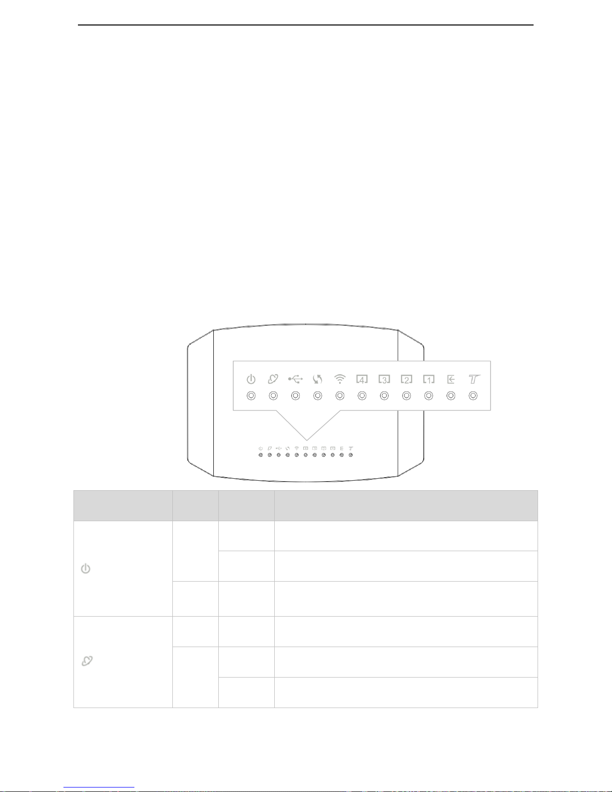
1.4.1 Front Panel
LED Indicator
Color
Status
Description
PWR
Red
Solid on
The device is starting.
Blinking
The device is upgrading.
Green
Solid on
The device is working properly.
INTERNET
Red
Solid on
No internet access.
Green
Solid on
The device is connected to the internet successfully.
Blinking
Data is being transmitted.
Page 11

3
USB
Green
Solid on
A USB device is properly connected and ready.
Blinking
Data is being transmitted.
Off
No USB device is detected, or the USB device is ejected safely.
WPS
Green
Solid on
for 2
mins->Off
A WPS connection is established.
Blinking
The device is performing WPS negotiation.
Off
The WPS feature is disabled, or the WPS feature is enabled but
the device does not perform WPS negotiation.
WLAN
Green
Solid on
The wireless feature is enabled.
Blinking
Data is being transmitted wirelessly.
Off
The wireless feature is disabled.
1-4
Green
Solid on
This port is properly connected.
Blinking
This port is transmitting data.
Off
No connection is detected on this port.
DSL
Green
Solid on
The DSL negotiation is completed.
Blinking
The device is doing DSL negotiation.
Off
No connection is detected on the DSL port.
This LED is reserved.
Page 12
4
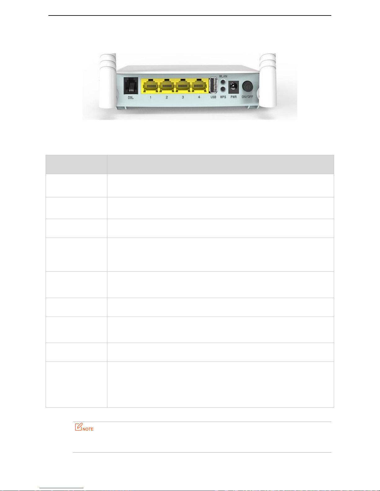
1.4.2 Rear panel
Button/Port
Description
ON/OFF
Power button. Used to turn on/off the modem router.
PWR
Power jack. Used to connect to the included power adapter for power supply.
WLAN
This button is used to enable or disable the wireless feature.
WPS
Enable the WPS function on the web UI of the modem router. Press this button for 3
seconds and then release it to perform the WPS negotiation process. Within 2 minutes,
enable the wireless device’s WPS feature to establish WPS connection.
1
This port serves as a LAN port by default. But if your link type is Ethernet, it serves as a
WAN port.
2/3
LAN Ports. Used to connect to a computer, switch, and so on.
4
If you enable IPTV feature of the modem router, this port serves as an IPTV port.
Otherwise, it is a LAN port.
DSL
RJ11 port. Used to connect the modem router to the internet via a telephone cable.
RST
*On the bottom
panel of the modem
router
Press this button for about 6 seconds and then release it to restore factory settings.
Please use the included power adapter for power supply. Use of a power adapter with different voltage
rating may damage the device.
Page 13
5
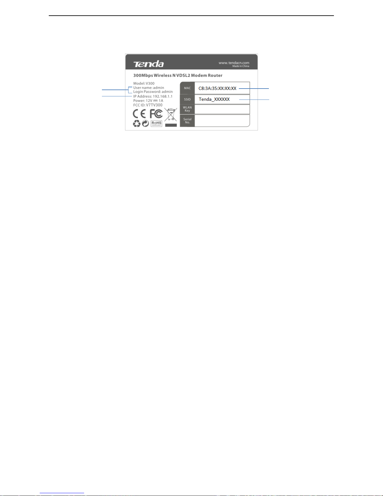
1.4.3 Product Label
1 Default login user name and password: When you log in to the web UI of the modem router, this information is
required.
2 Default login IP address of the modem router: Enter this IP address in the address bar of a web browser to log
in to the web UI of the modem router
3 MAC address of the modem router
4 Default wireless network name of the modem router
1 2 3
4
Page 14
6
2 Quick Setup
2.1 Connecting the Device to the Internet
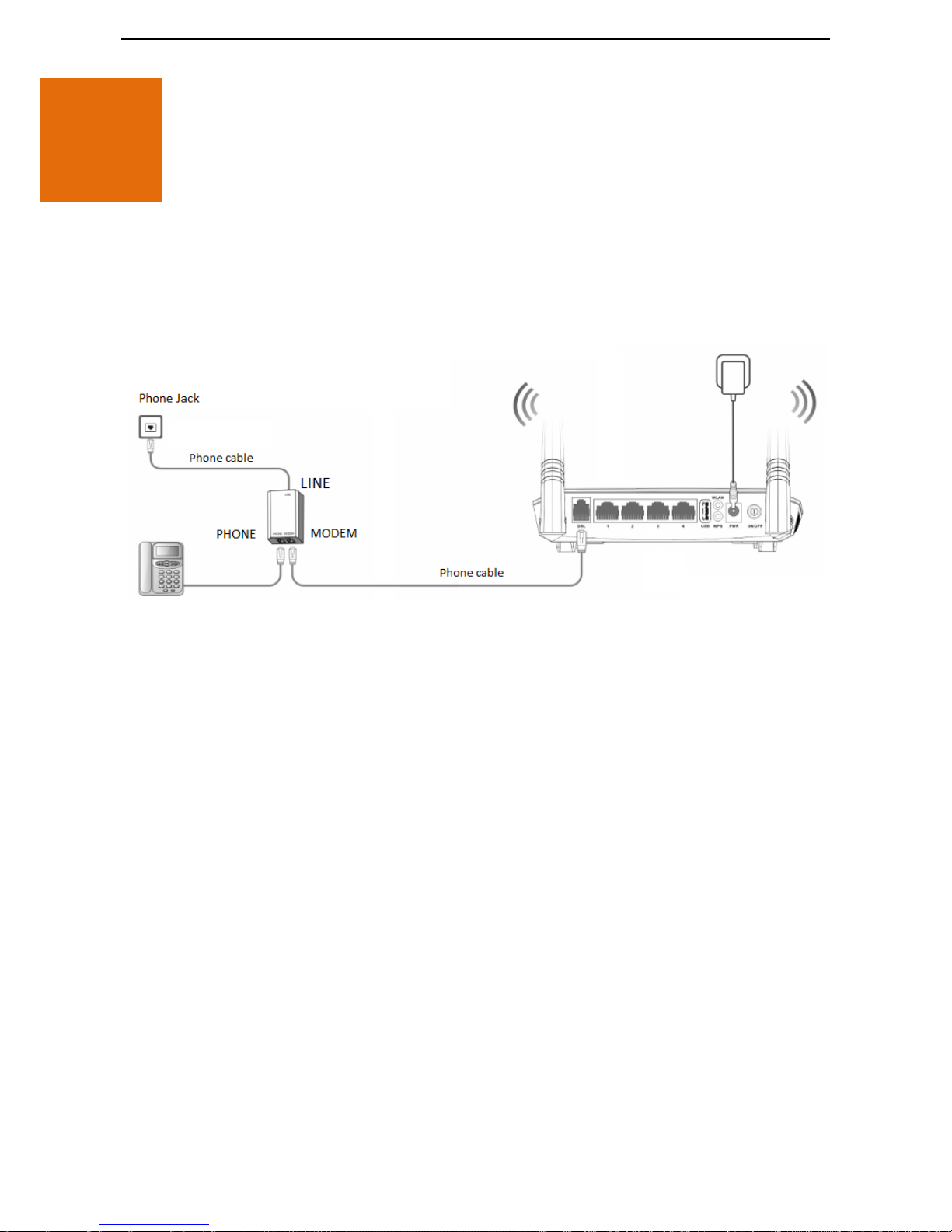
2.1.1 Phone Cable Connection
If you want to use phone service and internet service concurrently, connect the modem router as follows:
Step 1 Connect the LINE port of the included splitter to the phone jack.
Step 2 Connect the PHONE port of the splitter to your telephone.
Step 3 Connect the MODEM port of the splitter to the DSL port of the modem router.
Step 4 Power on the modem router.
--End
If you do not need to use the phone service, directly connect the phone jack to the DSL port of the modem
router.
2.1.2 Ethernet Cable Connection
When the modem router only functions as a wireless router, connect the modem router as follows:
Page 15

7
Connect the Ethernet jack to the port 1 of the modem router.
2.1.3 3G/4G Dongle
Insert a 3G/4G dongle provided by your ISP into USB port of the modem router for internet access.
2.2 Connecting the Device to a Client
2.2.1 Wireless Connection
This label is on the bottom panel of the modem router.
Use your smart device to search and connect to the default SSID (WiFi name) of the modem router. There is no
default WLAN Key (WiFi password) by default.
If either the SSID or WLAN key is changed, the wireless device is required to connect to the modem router again.
Page 16

8
2.2.2 Wired Connection
Connect your computer to an available LAN port (port 1, 2, 3, or 4) of the modem router.
2.3 Login
Step 1 Start a web browser on the computer connected to the modem router, enter 192.168.1.1 in the
address bar and tap Enter on the keyboard.
You’d better configure the modem router on a computer that connected to the modem router via an
Ethernet cable.
Step 2 Enter the default login user name and password (both are admin), and click Login.
--End
Page 17

9
2.4 Setting up an Internet Connection
2.4.1 Phone Cable Connection
If you connect the modem router to the internet via a phone cable, refer to the configuration in this part to
complete your internet settings.
VDSL
If the link type your internet service provider provided to you is VDSL, follow the procedures below:
Step 1 Log in to the web UI and enter the Home page.
Step 2 Link Type: Select VDSL.
Step 3 Connection Type: Select a connection type according to the instructions in the table below, and
complete the related internet parameters.
Connection Type
Description
PPPoE
Select thus type if your internet service provider (ISP)
provides a user name and password to you for internet
access.
IPoE
Dynamic IP
Select thus type if your ISP does not provide any parameters
to you for internet access.
Static IP
Select thus type if your ISP provides a static IP address and
other related information to you for internet access.
Bridge
Select thus type when this device only serves as a modem,
and you want to set up a dial-up connection or enter other
Page 18

10
internet parameters directly on your computer for internet
access.
Step 4 Click OK on the bottom of the page to apply the settings.
--End
ADSL
If the link type your internet service provider provided to you is ADSL, follow the procedures below:
Step 1 Log in to the web UI and enter the Home page.
Step 2 Link Type: Select ADSL.
Step 3 Connection Type: Select a connection type according to the instructions in the table below, and
complete the related internet parameters.
Connection Type
Description
PPPoE (PPP over Ethernet)
If your internet service provider (ISP) provides a user name
and password to you for internet access, your connection
type may be PPPoE or PPPoA, contact your ISP for details.
PPPoA (PPP over ATM)
IPoE (IP over
Ethernet)
Dynamic IP
Select thus type if your ISP does not provide any parameters
to you for internet access.
Static IP
If your internet service provider provides a static IP address
and other related information to you for internet access, your
connection type may be IPoE or IPoA, contact your ISP for
details.
IPoA (IP over
ATM)
Static IP
Bridge
Select thus type when this device only serves as a modem,
and you want to set up a dial-up connection or enter other
internet parameters directly on your computer for internet
access.
Step 4 Country/Region: Select your country or region.
Step 5 ISP: Select your internet service provider.
Step 6 Enter the related internet parameters provided by your ISP.
Step 7 Click OK on the bottom of the page to apply the settings.
--End
If your country/region and ISP are not covered in the drop-down list, select Other, and enter the VPI
and VCI manually. If you do not know the VPI and VCI, contact your ISP for help.
2.4.2 Ethernet Cable Connection
If you connect the modem router to the internet via an Ethernet cable, refer to the configuration in this part to
complete your internet settings. In this case, this device only serves as a wireless router.
Page 19

11
PPPoE
Use thus type if you can access the internet only after setting up a dial-up connection on the computer using a
user name and password provided by your ISP.
Step 1 Log in to the web UI and enter the Home page.
Step 2 Link Type: Select Ethernet.
Step 3 Connection Type: Select PPPoE.
Step 4 Enter the user name and password.
Step 5 Click OK on the bottom of the page to apply the settings.
--End
Page 20

12
IPoE
Dynamic IP
Use thus type if you can access the internet only after setting a static IP address and other related information on
your computer.
Step 1 Log in to the web UI and enter the Home page.
Step 2 Link Type: Select Ethernet.
Step 3 Connection Type: Select IPoE.
Step 4 Address Mode: Select Dynamic IP.
Step 5 Click OK on the bottom of the page to apply the settings.
--End
Static IP
Use thus type if you can access the internet only after setting a static IP address and other related information on
your computer.
Step 1 Log in to the web UI and enter the Home page.
Page 21

13
Step 2 Link Type: Select Ethernet.
Step 3 Connection Type: Select IPoE.
Step 4 Address Mode: Select Static IP.
Step 5 Enter the static IP address, and other related parameters.
Step 6 Click OK on the bottom of the page to apply the settings.
--End
Bridge
Select thus type when this device only serves as a switch, and you want to set up a dial-up connection or enter
other internet parameters directly on your computer for internet access.
Step 1 Log in to the web UI and enter the Home page.
Step 2 Link Type: Select Ethernet.
Step 3 Connection Type: Select Bridge.
Step 4 Click OK on the bottom of the page to apply the settings.
--End
2.4.3 3G/4G Dial
If you connect the modem router to the internet via a 3G/4G dongle, refer to the configuration in this part to
complete your internet settings.
Page 22

14
Step 1 Log in to the web UI and enter the Home page.
Step 2 Link Type: Select 3G/4G.
Step 3 Country: Select your country.
Step 4 ISP: Select your internet service provider.
Step 5 (Optional) APN/Dial number/Username/Password: Generally, if you select correct country and ISP,
the necessary parameters can be automatically filled in. If not, enter them manually according to the
internet parameters your ISP provided.
Step 6 Click OK on the bottom of the page to apply the settings.
--End
2.5 Wireless Setup
The wireless feature is enabled by default. The default SSID of the modem router is Tenda_XXXXXX, where
XXXXXX is the last six characters of the MAC address of the modem router. There is no Wireless Key (WiFi
password) by default. But there is a preset WiFi password 12345678 in the Wireless Key box. It takes effects
when the OK button on the bottom of the page is clicked.
Page 23

15
To customize a WiFi name and password:
Step 1 Log in to the web UI and enter the Home page.
Step 2 Enter a new WiFi name in the Wireless SSID box.
Step 3 Enter a new WiFi password in the Wireless Key box.
Step 4 Click OK to apply the settings.
--End
To disable wireless feature:
Uncheck the Wireless Enable option, and click OK.
When the wireless feature is disabled, wireless device cannot connect to the modem router wirelessly.
Page 24

16
3 Device Info
3.1 Summary
Here you can view WAN status, xDSL information, and the device information
3.2 WAN
Here you can view the WAN Information including Interface, Description, Type, IGMP, NAT, Firewall, Status, IPv4
Address and VLAN ID.
Page 25

17
3.3 Statistics
Here you can view the packets received and transmitted on LAN port, WAN port, DSL port, and USB port.
Statistics--LAN: Displays the packets received and transmitted on the LAN ports. Click Reset Statistics to clear the
current statistics.
Statistics--WAN: Displays the packets received and transmitted on the WAN port. Click Reset Statistics to clear
the current statistics.
Page 26

18
Statistics--xDSL: Displays the packets received and transmitted on the DSL port. Click Reset Statistics to clear the
current statistics.
Page 27

19
Statistics—3G/4G: Displays the packets received and transmitted on the USB port. Click Clear to clear the current
statistics.
Page 28

20
3.4 Route
Here you can view the route table。
3.5 ARP
Here you can view the IP and MAC addresses of the devices that connected to the modem router either in wired
manner or in wireless manner.
Page 29

21
3.6 DHCP
Here you can view the DHCP leases, including IP and MAC addresses of the devices, hostnames and remaining
lease time.
Page 30
22
4 Advanced Setup
4.1 Layer2 Interface
Choose Advanced > Advanced Setup > Layer2 Interface to enter the Layer2 Interface page.
This router provides three Layer2 Interfaces:
- PTM interface for VDSL broadband internet service
- ATM interface for ADSL broadband internet service
- ETH interface for connecting to the Internet via an Ethernet cable
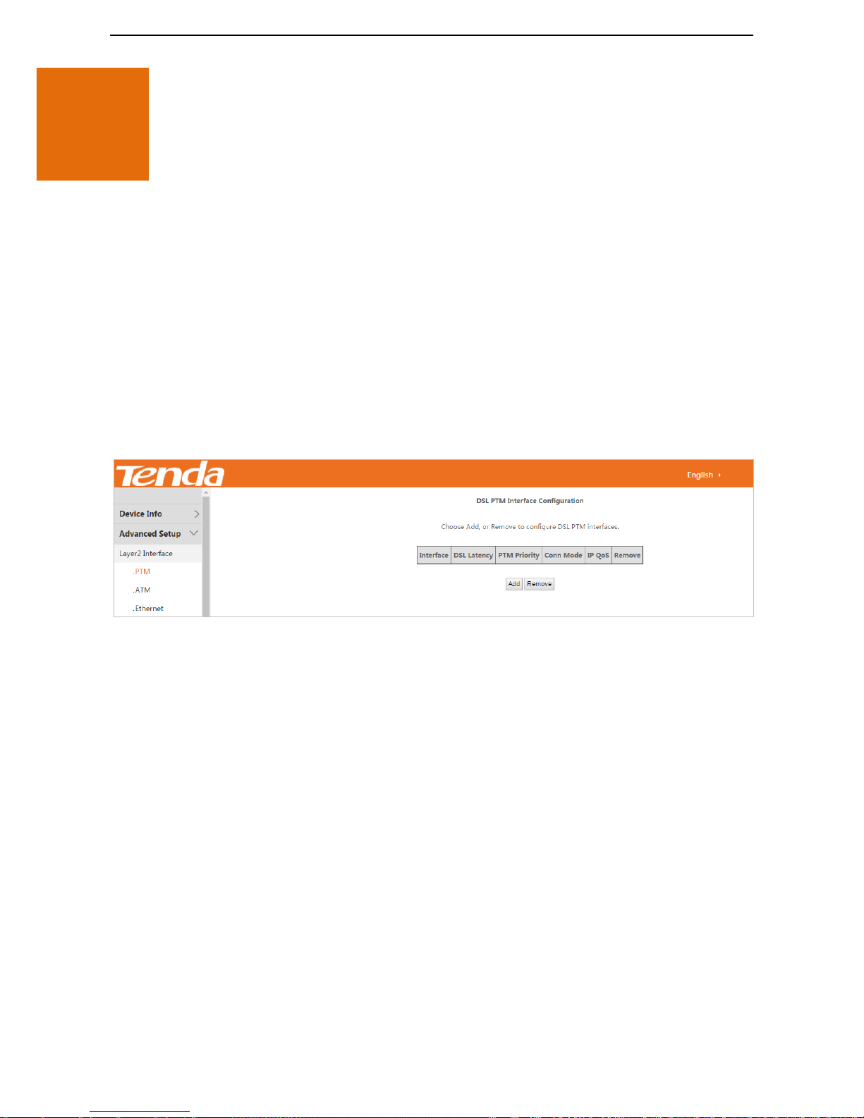
4.1.1 To Set up the PTM Interface
Log in to the web UI, choose Advanced > Advanced Setup > Layer2 Interface > PTM to enter the following page.
Step 1 Click Add.
Step 2 Leave the parameters for queue weight unchanged, and click Apply/Save.
Page 31

23
And then refer to To Set up WAN Service for PTM Interface to configure the WAN service for internet access.
--End
4.1.2 To Set up the ATM Interface
Log in to the web UI, choose Advanced > Advanced Setup > Layer2 Interface > ATM to enter the following page.
Step 1 Click Add.
Step 2 Enter the VPI and VCI values.
Step 3 Select a DSL Link Type according to the instructions in the table below, and leave other options
unchanged. EoA (EoA is for PPPoE, IPoE, and Bridge.), PPPoA or IPoA.
Step 4 Click Apply/Save on the bottom of the page.
Connection Type
Description
PPPoE (PPP over Ethernet)
If your internet service provider (ISP) provides a user name and
password to you for internet access, your connection type may be
PPPoE or PPPoA, contact your ISP for details.
PPPoA (PPP over ATM)
IPoE (IP over
Ethernet)
Dynamic IP
Select thus type if your ISP does not provide any parameters to you for
internet access.
Page 32

24
Static IP
If your internet service provider provides a static IP address and other
related information to you for internet access, your connection type
may be IPoE or IPoA, contact your ISP for details.
IPoA (IP over
ATM)
Static IP
Bridge
Select thus type when this device only serves as a modem, and you
want to set up a dial-up connection or enter other internet parameters
directly on your computer for internet access.
And then refer to To Set up WAN Service for ATM Interface to configure the WAN service for internet access.
--End
If you are unsure about the VPI/VCI parameters, refer to Appendix 8.4 VPI/VCI List. If the ISP and the
VPI/VCI information is not covered there, ask your ISP to provide it.
4.1.3 To Set up the Ethernet Interface
Log in to the web UI, choose Advanced > Advanced Setup > Layer2 Interface > Ethernet to enter the following
page.
Step 1 Click Add.
Step 2 Click Apply/Save.
Page 33

25
And then refer to To Set up WAN Service for Ethernet Interface to configure the WAN service for internet access.
--End
4.2 WAN Service
Choose Advanced > Advanced Setup > WAN Service to enter the WAN Service page.
4.2.1 To Set up WAN Service for PTM Interface
Log in to the web UI, choose Advanced > Advanced Setup > WAN Service to enter the following page.
Step 1 Click Add.
Step 2 Select the interface you create in Layer2 Interface, interface ptm0/(0_1_1) here.
Step 3 Click Next.
Step 4 Select a WAN service type according to the instructions in the table below. Here take PPPoE as an
example.
Page 34

26
Connection Type
Description
PPP over Ethernet (PPPoE)
Select thus type if your internet service provider (ISP) provides a user
name and password to you for internet access.
IP over Ethernet
Dynamic IP
Select thus type if your ISP does not provide any parameters to you for
internet access.
Static IP
Select thus type if your ISP provides a static IP address and other
related information to you for internet access.
Bridging
Select thus type when this device only serves as a modem, and you
want to set up a dial-up connection or enter other internet parameters
directly on your computer for internet access.
Step 5 Select PPP over Ethernet.
Step 6 Network Protocol Selection: Select your network protocol type. The modem router provides three
types of network protocol: IPv4 Only, IPv4&IPv6, and IPv6 Only. Here take IPv4 Only as an example.
Step 7 Click Next.
Step 8 PPP Username/PPP Password/: Enter the PPPoE user name and password provided by your ISP.
Step 9 (Optional) PPPoE Service: Enter the PPPoE service name if it is provided.
Page 35

27
Optional Step: MAC Clone
If you can only access the internet via a specified computer, it may indicate that your ISP binds the internet
service to the MAC address of the computer to restrict access. In this case, you need to clone the MAC address of
this computer to the modem router for internet access.
Procedure
Select the MAC address box.
Enter the MAC address of the computer. If you use this computer to configure the modem router, you
can directly click Clone MAC to copy the MAC address to the modem router.
Step 10 Click Next.
Step 11 Leave the configuration unchanged, and click Next.
Page 36

28
Step 12 Enter the DNS IP addresses information if they are provided by your ISP. If not, leave then blank.
Step 13 Click Next.
Step 14 Check the parameters you select or set, and click Apply/Save.
Page 37

29
--End
The WAN service you set is shown in WAN Service page.
4.2.2 To Set up WAN Service for ATM Interface
Log in to the web UI, choose Advanced > Advanced Setup > WAN Service to enter the following page.
Step 1 Click Add.
Page 38

30
Step 2 Select the interface you create in Layer2 Interface, interface atm0/(0_1_35) here.
Step 3 Click Next.
Step 4 Select a WAN service type according to the instructions in the table below. Here take PPPoE as an
example.
Connection Type
Description
PPP over Ethernet (PPPoE)
Select thus type if your internet service provider (ISP) provides a user
name and password to you for internet access.
IP over Ethernet
Dynamic IP
Select thus type if your ISP does not provide any parameters to you for
internet access.
Static IP
Select thus type if your ISP provides a static IP address and other
related information to you for internet access.
Bridging
Select thus type when this device only serves as a modem, and you
want to set up a dial-up connection or enter other internet parameters
directly on your computer for internet access.
Step 5 Select PPP over Ethernet.
Step 6 Network Protocol Selection: Select your network protocol type. The modem router provides three
types of network protocol: IPv4 Only, IPv4&IPv6, and IPv6 Only. Here take IPv4 Only as an example.
Step 7 Click Next.
Page 39

31
Step 8 PPP Username/PPP Password/: Enter the PPPoE user name and password provided by your ISP.
Step 9 (Optional) PPPoE Service: Enter the PPPoE service name if it is provided.
Optional Step: MAC Clone
If you can only access the internet via a specified computer, it may indicate that your ISP binds the internet
service to the MAC address of the computer to restrict access. In this case, you need to clone the MAC address of
this computer to the modem router for internet access.
Procedure
Select the MAC address box.
Page 40

32
Enter the MAC address of the computer. If you use this computer to configure the modem router, you
can directly click Clone MAC to copy the MAC address to the modem router.
Step 10 Click Next.
Step 11 Leave the configuration unchanged, and click Next.
Step 12 Enter the DNS IP addresses information if they are provided by your ISP. If not, leave then blank.
Step 13 Click Next.
Page 41

33
Step 14 Check the parameters you select or set, and click Apply/Save.
--End
The WAN service you set is shown in WAN Service page.
Page 42

34
4.2.3 To Set up WAN Service for Ethernet Interface
Log in to the web UI, choose Advanced > Advanced Setup > WAN Service to enter the following page.
Step 1 Click Add.
Step 2 Select the interface you create in Layer2 Interface, interface atm0/(0_1_35) here.
Step 3 Click Next.
Step 4 Select a WAN service type according to the instructions in the table below. Here take PPPoE as an
example.
Connection Type
Description
PPP over Ethernet (PPPoE)
Select thus type if your internet service provider (ISP) provides a user
name and password to you for internet access.
IP over Ethernet
Dynamic IP
Select thus type if your ISP does not provide any parameters to you for
internet access.
Page 43

35
Static IP
Select thus type if your ISP provides a static IP address and other
related information to you for internet access.
Bridging
Select thus type when this device only serves as a modem, and you
want to set up a dial-up connection or enter other internet parameters
directly on your computer for internet access.
Step 5 Select PPP over Ethernet.
Step 6 Network Protocol Selection: Select your network protocol type. The modem router provides three
types of network protocol: IPv4 Only, IPv4&IPv6, and IPv6 Only. Here take IPv4 Only as an example.
Step 7 Click Next.
Step 8 PPP Username/PPP Password/: Enter the PPPoE user name and password provided by your ISP.
Step 9 (Optional) PPPoE Service: Enter the PPPoE service name if it is provided.
Optional Step: MAC Clone
Page 44

36
If you can only access the internet via a specified computer, it may indicate that your ISP binds the internet
service with the MAC address of the computer to restrict access. In this case, you need to clone the MAC address
of this computer to the modem router for internet access.
Procedure
Select the MAC address box.
Enter the MAC address of the computer. If you use this computer to configure the modem router, you
can directly click Clone MAC to copy the MAC address to the modem router.
Step 10 Click Next.
Step 11 Leave the configuration unchanged, and click Next.
Step 12 Enter the DNS IP addresses information if they are provided by your ISP. If not, leave then blank.
Step 13 Click Next.
Page 45

37
Step 14 Check the parameters you select or set, and click Apply/Save.
--End
The WAN service you set is shown in WAN Service page.
Page 46

38
4.3 VPN
A VPN is a logical private network set up over a public network (usually the internet) without physical lines.
This modem router can function as a PPTP/L2TP client. The following section describes how to configure the
router as a PPTP/L2TP client.
4.3.1 L2TP Client
Choose Advanced > Advanced Setup > VPN > L2TP Client to enter the configuration page.
Step 1 Click Add.
Step 2 Set Tunnel Name and L2TP Server IP address/domain name based on the information provided by
your ISP, and select an Associated WAN Interface.
Step 3 Click Next.
Page 47

39
Step 4 Set PPP Username, PPP Password, and Service Name based on the information provided by your ISP.
Step 5 Click Next.
Step 6 Click Next.
Page 48

40
Step 7 Enter the DNS IP addresses information if they are provided by your ISP. If not, leave then blank.
Step 8 Check the parameters you select or set, and click Apply/Save.
Page 49

41
--End
The L2TP WAN service you set is shown in the L2TP Client page.
4.3.2 PPTP Client
Choose Advanced > Advanced Setup > VPN > PPTP Client to enter the configuration page.
Page 50

42
Step 1 Click Add.
Step 2 Set Tunnel Name and L2TP Server IP address/domain name based on the information provided by
your ISP, and select an Associated WAN Interface.
Step 3 Click Next.
Step 4 Set PPP Username, PPP Password, and Service Name based on the information provided by your ISP.
Step 5 Click Next.
Page 51

43
Step 6 Click Next.
Step 7 Enter the DNS IP addresses information if they are provided by your ISP. If not, leave then blank.
Page 52

44
Step 8 Check the parameters you select or set, and click Apply/Save.
--End
The PPTP WAN service you set is shown in the PPTP Client page.
Page 53

45
4.4 3G/4G Dial
If you connect the modem router to the internet via a 3G/4G dongle, and do not complete the internet settings
in Quick Setup > 3G/4G Dial, you can refer to the configuration in this part.
Choose Advanced > Advanced Setup > 3G/4G Dial to enter the configuration page.
Step 1 Select your country and ISP.
Step 2 APN/Dial number/Username/Password/PIN Code: Generally, if you select correct country and ISP, the
necessary parameters can be automatically filled in. If not, set them manually based on the internet
parameters provided by your ISP.
Step 3 Click Apply/Save.
Page 54

46
--End
4.5 LAN
Here you can configure the LAN IP Address settings. This IP address is to be used to log in to the web UI of the
modem router.
4.5.1 IPv4
Choose Advanced > Advanced Setup > LAN to enter the configuration page.
Page 55

47
Parameter
Description
IP Address
It specifies the LAN IP address of the modem router, that is, the login address of the
web UI of the modem router.
Subnet Mask
The LAN subnet mask of the modem router. Combined with the IP address, the IP
Subnet Mask allows a device to know which other addresses are local to it, and
which must be reached through a gateway or modem router. You can change the
subnet mask to fit your network.
Enable IGMP Snooping
Check to enable the IGMP Snooping feature and select either of the following two
modes: Standard Mode and Blocking Mode.
Disable DHCP Server
Disable DHCP Server: It indicates that no IP address is assigned to the devices
connected to the router (such as laptops and mobile phones). These devices can
access the internet only after IP addresses are manually set on them. Manual IP
address setting is complicated and may easily cause IP conflicts. Generally, it is
recommended that you enabled the DHCP server.
Enable DHCP Server
Enable DHCP Server: It indicates that the server that assigns one IP address within a
specified IP address range to each device connected to the router.
Start IP Address: Specify the start IP address of the range for the IP address pool of
the DHCP server.
End IP Address: Specify the end IP address of the range for the IP address pool of the
DHCP server.
Leased Time
It specifies the validity period of one IP address assigned to a device connected to
the router.
Static IP Lease List
Displays a list of devices with reserved static IP addresses.
Add Entries
Click to add a static IP lease entry. A maximum 32 entries can be configured.
Remove Entries
Click to remove a static IP lease entry.
Configure the second IP
Address and Subnet
Mask for LAN interface
If you want to configure two IP addresses for the LAN interface, you can check this
option and enter the second IP Address and Subnet Mask manually.
Apply/Save
After you configure all the needed settings, click this button to apply and save them.
DHCP Reservation
Generally, IP addresses assigned by the modem router to devices are changeable. Some functions, such as DMZ
Host and virtual server, require static device IP addresses. In this case, you can use the DHCP reservation function
to bind fixed IP addresses with the devices involved in the functions.
To configure the DHCP reservation function, choose Advanced > Advanced Setup > LAN. Configure the function
as follows.
Page 56

48
Step 1 Click Add Entries.
Step 2 Set MAC address to the MAC address of the device.
Step 3 Set IP Address to an IP address in the same segment as the LAN IP address of the modem router, such
as any IP address in 192.168.1.3~192.168.1.254. It cannot be the same as the LAN IP address of the
modem router. (The default LAN IP address of the modem router is 192.168.1.1.)
Step 4 Click Apply/Save.
--End
The added entry appears in the table.
Page 57

49
To Configure a Second IP Address for LAN Interface
Choose Advanced > Advanced Setup > LAN to enter the configuration page.
Step 1 Select the Configure the second IP Address and Subnet Mask for LAN interface option.
Step 2 Set IP Address to another IP address that specifies a network segment, like 192.168.2.1.
Step 3 Set Subnet Mask to a subnet mask that fit the network segment, like 255.255.255.0.
Step 4 Click Apply/Save.
--End
The second LAN IP address can also be used to log in to the web UI of the modem router.
4.5.2 IPv6
Choose Advanced > Advanced Setup > LAN > IPv6config to enter the configuration page.
Page 58

50
IPv6 address can only be Aggregate Global Unicast Address and Unique Local Address. Link-Local
Unicast Addresses and Multicast Addresses are not permitted.
The IPv6 address must be entered with a prefix length.
Parameter
Description
Enable DHCPv6 Server
Check to enable the DHCPv6 Server.
Stateless
If selected, IPv6 clients will generate IPv6 addresses automatically based on the Prefix
Delegation's IPv6 prefix and their own MAC addresses.
Stateful
Stateful DHCPv6 is supported based on the assumption of prefix length less than 64.
Select this option and configure the start/end interface ID and leased time. The router
will automatically assign IPv6 addresses to IPv6 clients.
Start interface ID/End
interface ID
Specify the start/end interface ID Interface ID does NOT support ZERO COMPRESSION
"::". Please enter the complete information. For example: Please enter "0:0:0:2"
instead of "::2".
Leased Time (hour)
The lease time is a time length that the IP address is assigned to each device before it
is refreshed.
Enable RADVD
The RADVD (Router Advertisement Daemon) implements link-local advertisements of
IPv6 router addresses and IPv6 routing prefixes using the Neighbor Discovery Protocol
(NDP) and is used by system administrators in stateless auto configuration methods of
network hosts on Internet Protocol version 6 networks. Check the checkbox to enable
the RADVD.
Enable ULA Prefix
Advertisement
If enabled, the router will advertise ULA prefix periodically.
Randomly Generate
If selected, address prefix can be automatically generated.
Statically Configure
If you select this option, you need to manually configure the address prefix and life
Page 59

51
time.
Prefix
Specify the prefix.
Preferred Life Time
(hour)
Specify the preferred life time in hour.
Valid Life Time (hour)
Specify the valid life time in hour.
Enable MLD Snooping
MLD is used by IPv6 routers for discovering multicast listeners on a directly attached
link. If disabled on layer2 devices, IPv6 multicast data packets will be broadcast on the
entire layer2; if enabled, these packets will be multicast to only specified recipient
instead of being broadcast on the entire layer2.
4.6 NAT
4.6.1 Virtual Server
If computers are connected to the modem router to form a LAN and access the internet through the modem
router, internet users cannot access the hosts on the LAN. Therefore, the servers, such as web servers, email
servers, and FTP servers, on the LAN are inaccessible to internet users. To enable internet users to access a LAN
server, enable the virtual server function of the modem router, and map one service port of the virtual server to
the IP address of the LAN server. This enables the modem router to forward the requests arriving at the port
from the internet to the LAN server.
Choose Advanced> Advanced Setup > NAT > Virtual Server to enter the configuration page.
Click Add to configure the function.
Page 60

52
Parameter
Description
Use Interface
Select a WAN connection to which you wish to apply the rules. When there is only one
WAN connection available, the rules will be automatically applied to it.
Service Name
Select a Service: Allows you to select an existing service from the drop-down list.
Custom Service: Allows you to customize a service.
Server IP Address
Enter the IP address of your local computer that will provide this service.
External Port Start and
External Port End
These are the start number and end number for the public ports at the internet
interface.
Protocol
Select a protocol from the Protocol drop-down list. If you are unsure, select TCP/UDP.
Internal Port Start and
Internal Port End
These are the start number and end number for the ports of a computer on the
router’s local area network (LAN).
Application Example
You have set up an FTP server on your LAN:
- An FTP server (using the default port number of 21) at the IP address of 192.168.1.100
And want your friends to access the FTP server and web server on default port over the internet. To access your
FTP or web server from the Internet, a remote user has to know the Internet IP address or internet name of the
modem router, such as www.tendacn.com. In this example, we assume the internet IP address of your router is
183.37.227.201. Then follow instructions below:
To configure the router to make your local FTP server public:
Choose Advanced > Advanced Setup > NAT > Virtual Server to enter the configuration page.
Page 61

53
Step 1 Click Add.
Step 2 Select FTP that you wish to host on your network from the Select a Service drop-down list. The port
number (21) used by this service will then be automatically populated.
If you wish to define the service yourself, enter a descriptive name in the Custom Service, say My FTP, and then
manually set the port number (21) used by this service in the Internal Port Start, Internal Port End, External Port
Start and External Port End.
Step 3 Select a protocol from the Protocol drop-down list. If you are unsure, select TCP/UDP.
Step 4 In the Server IP Address field, enter the last digit of the IP address of your local computer that offers
this service. Here in this example, we enter 192.168.1.100.
Step 5 Click the Apply/Save.
--End
Remote Access:
Your friends can access your FTP server by entering "ftp://183.37.227.201" in the address bar of a web browser.
4.6.2 Port Triggering
Some applications, such as games, video conferencing, and remote access, require that specific ports in the
router's firewall be opened for access by the applications. Port Trigger dynamically opens up the 'Open Ports' in
the firewall when an application on the LAN initiates a TCP/UDP connection to a remote party using the
'Triggering Ports'. The Router allows the remote party from the WAN side to establish new connections back to
the application on the LAN side using the 'Open Ports'.
Choose Advanced> Advanced Setup > NAT > Port Triggering to enter the configuration page.
Page 62

54
Click Add to configure the function.
Parameter
Description
Use Interface
Select a WAN connection to which you wish to apply the rules. When there is only
one WAN connection available, the rules will be automatically applied to it.
Application Name
Select an application: Allows you to select an existing service from the drop-down
list.
Custom application: Allows you to customize a service.
Trigger Port Start/Trigger
Port End
The port range for an application to initiate connections.
Trigger Protocol
Select the protocol from the drop-down list. If you are unsure, select TCP/UDP.
Open Port Start/ Open
Port End
These are the starting number and ending number for the ports that will be
automatically opened by the built-in firewall when connections initiated by an
application are established.
4.6.3 DMZ Host
The default DMZ (De-Militarized Zone) host feature is helpful when you are using some online games and
Page 63

55
videoconferencing applications that are not compatible with NAT (Network Address Translation).
Choose Advanced> Advanced Setup > NAT > DMZ Host to enter the configuration page.
DMZ Host IP Address: The IP Address of the device for which the firewall of the modem router is disabled.
Ensure that the IP address is a static IP address. The DMZ host should be connected to a LAN port of the modem
router.
A DMZ host is not protected by the firewall of the router. A hacker may leverage the DMZ host to
attack your LAN. Therefore, enable the DMZ function only when necessary.
Manually set the IP address of the LAN computer that functions as a DMZ host, to prevent IP
address changes, which lead to DMZ function failures.
Security software, antivirus software, and the built-in OS firewall of the computer may cause DMZ
function failures. Disable them when using the DMZ function. If the DMZ function is not required,
it is recommended that you disable it and enable your firewall, security, and antivirus software.
To configure the DMZ function, perform the following procedure:
Step 1 Click Add.
Step 2 Set DMZ Host IP Address to an IP address of the DMZ host.
Step 3 Click Save/Apply.
Page 64

56
--End
4.6.4 Multi-NAT
Multi-NAT is a network function whereby one network address is rewritten (translated) to another address:
Network Address Translation is frequently used to allow multiple network nodes (computers or inter-networked
devices) to share a single internet (or local network) IP address. Multi-NAT has "one to one", and "many to one"
types of configurations.
Choose Advanced> Advanced Setup > NAT > Multi-NAT to enter the configuration page.
Click Add to configure the function.
Page 65

57
Parameter
Description
Interface
Select a WAN interface that the function is used.
Type
One-to-One: Set a route from a local IP address to a public IP address
Many-to-One: Set a route from many local IP addresses to a public IP address
Local IP
To specify a local IP address
Local Start/End IP
To specify a range of local IP address
Public IP
To specify a public IP address
To configure the Multi-NAT function, perform the following procedure:
Step 1 Click Add.
Step 2 Select an interface from the drop-down list.
Step 3 Select a type. If you only need to set a route for a local IP address, select One-to-One. Otherwise,
select Many-to-One.
Step 4 Set Local IP to a local IP address.
Step 5 Set Public IP to a public IP address.
Step 6 Click Apply/Save.
--End
The local IP and Public IP you set should be static IP addresses.
4.6.5 UPnP
This function enables the modem router to map ports. It can enhance user experience especially during online
gaming and P2P download.
Choose Advanced> Advanced Setup > NAT > UPnP to enter the configuration page.
Page 66

58
4.7 Security
4.7.1 Dos Defence
This function allows you to enable ICMP-FLOOD Attack Filtering, UDP-FLOOD Attack Filtering, and
TCP-SYN-FLOOD Attack Filtering to defend the modem router from ICMP-FLOOD attack, UDP-FLOOD attack, and
TCP-SYN-FLOOD attack.
Choose Advanced> Advanced Setup > Security > Dos Defense to enter the configuration page.
To enable the Dos Defense function, perform the following procedure:
Step 1 Select the Enable of Dos Protection option.
Step 2 Select the corresponding attack filtering.
Step 3 Click Save.
--End
Page 67

59
Click Blocked DoS Host List can check the attacks the modem router blocks.
4.7.2 IP Filtering
This function can forbid the LAN devices to access the internet or allow WAN devices to visit the devices in the
LAN.
Outgoing
By default, all outgoing IP traffic from LAN is allowed, but some IP traffic can be BLOCKED by setting up filters.
The Outgoing function allows you to create a filter rule to identify outgoing IP traffic by specifying a new filter
name and at least one condition.
Choose Advanced> Advanced Setup > Security > IP Filtering > Outgoing to enter the configuration page.
To configure the Outgoing function, perform the following procedure:
Step 1 Click Add.
Step 2 Filter Name: Enter a descriptive filtering name.
Step 3 IP Version: Select your IP protocol, IPv4 or IPv6.
Step 4 Protocol: Select a protocol for the filter rule.
Step 5 Source IP address [/prefix length]: Enter the LAN IP address to be filtered.
Step 6 Source Port (port or port: port): Specify a port number or a range of ports used by LAN PCs to access
Page 68

60
internet. If you are not sure, leave it blank.
Step 7 Destination IP address [/prefix length]: Specify the external network IP address to be accessed by
specified LAN PCs.
Step 8 Destination Port (port or port:port): Specify a port number or a range of ports used by LAN PCs to
access external network.
Step 9 Click Apply/Save.
--End
Incoming
When the firewall is enabled on a WAN or LAN interface, all incoming IP traffic is BLOCKED. However, some IP
traffic can be ACCEPTED by setting up filters. The Incoming function allows you to create a filter rule to identify
incoming IP traffic by specifying a new filter name and at least one condition.
Choose Advanced> Advanced Setup > Security > IP Filtering > Incoming to enter the configuration page.
To configure the Outgoing function, perform the following procedure:
Step 1 Click Add.
Step 2 Filter Name: Enter a descriptive filtering name.
Step 3 IP Version: Select your IP protocol, IPv4 or IPv6.
Step 4 Protocol: Select a protocol for the filter rule.
Step 5 Source IP address [/prefix length]: Enter the internal IP address [/prefix length] to be filtered.
Step 6 Source Port (port or port: port): Specify a port number or a range of ports used by PCs from external
network to access your internal network.
Page 69

61
Step 7 Destination IP address [/prefix length]: Specify the internal network IP address [/prefix length] to be
accessed by the specified PCs from external network.
Step 8 Destination Port (port or port:port): Specify a port number or a range of ports used by PCs from
external network to access your internal network.
Step 9 Click Apply/Save.
--End
4.7.3 MAC Filtering
The MAC filtering is effective only when you create a Bridging WAN service. There are two policies of the
function:
FORWARDED indicates that all MAC layer frames will be FORWARDED except those matching with any of the
specified rules in the following table.
BLOCKED indicates that all MAC layer frames will be BLOCKED except those matching with any of the specified
rules in the following table.
Choose Advanced> Advanced Setup > Security > MAC Filtering to enter the configuration page.
To add a FORWARDED rule, perform the following procedure:
Step 1 Click Add.
Step 2 Protocol Type: Select a protocol type from the drop-down list.
Step 3 Destination MAC Address: Enter the destination MAC address apply the MAC filtering rule to which
you wish to apply the MAC filtering rule.
Step 4 Source MAC Address: Enter the source MAC address to which you wish to apply the MAC filtering rule.
Step 5 Frame Direction: Select a frame direction from the drop-down list.
Step 6 WAN Interfaces: Select a WAN interface from the drop-down list.
Step 7 Click Save/Apply.
Page 70

62
--End
To change the policy from FORWARDED to BLOCKED, perform the following procedure:
Step 1 Select Change box.
Step 2 Click Change Policy.
--End
Verification
The policy is change to BLOCKED.
Page 71

63
To add a BLOCKED rule, perform the following procedure:
Step 1 Change the policy to BLOCKED.
Step 2 Click Add.
Step 3 Protocol Type: Select a protocol type from the drop-down list.
Step 4 Destination MAC Address: Enter the destination MAC address apply the MAC filtering rule to which
you wish to apply the MAC filtering rule.
Step 5 Source MAC Address: Enter the source MAC address to which you wish to apply the MAC filtering rule.
Step 6 Frame Direction: Select a frame direction from the drop-down list.
Step 7 WAN Interfaces: Select a WAN interface from the drop-down list.
Step 8 Click Save/Apply.
--End
4.8 Parental Control
This function enables you to control internet connectivity availability and content accessibility for devices
connected to the router, ensuring healthy internet usage.
4.8.1 Time Restriction
Time Restriction adds time of day restriction to a special LAN device connected to the modem Router.
To add a time restriction rule, perform the following procedure:
Choose Advanced >Advanced Setup > Parental Control >Time Restriction to enter the configuration page.
Step 1 Click Add.
Page 72

64
Step 2 User Name: Specify a user name for this rule. It must be 1-32 characters, and not including space.
Step 3 Select Browser’s MAC Address if the rule is applied for the computer where the browser is running. If
not, select Other MAC Address, and enter the MAC address of a computer that the rule is applies for.
Step 4 Days of week: Click to select the days of the week during which the rule takes effect.
Step 5 Start Blocking Time/End Blocking Time: Specify time of day restriction for the rule. Within this
specified time length of the day, this LAN device is blocked from internet. For example, if you set start
Blocking Time to 23:00, and End Blocking Time to 06:00, the device this rule is applied for cannot
access the internet during 23:00~06:00.
Step 6 Click Apply/Save.
--End
4.8.2 URL Filter
URL Filter adds specific URL restrictions to a special LAN device
To add a URL Filter rule, perform the following procedure:
Choose Advanced >Advanced Setup > Parental Control >URL Filter to enter the configuration page.
Step 1 Select Exclude or Include.
Exclude indicates that the URLs added to the list are not allowed to visit.
Include indicates that only the URLs added to the list are allowed to visit.
Step 2 Click Add.
Step 3 Enter a URL. For example, Set URL Address to www.google.com.
Page 73

65
Step 4 Click Apply/Save.
--End
4.9 ALG
ALG allows you to enable some configurations.
4.10 Bandwidth Conrtol
If multiple devices access the internet through the modem router, bandwidth control is recommended, so that
high-speed file download by a device does not reduce the internet access speed of the other devices.
Choose Advanced > Advanced Setup > Bandwidth Control to enter the configuration page.
Page 74

66
To add a bandwidth control rule, perform the following procedure:
Step 1 Select Enable Bandwidth Control.
Step 2 Specify a name for the rule.
Step 3 Specify an IP address, or an IP address range.
Step 4 Specify a maximum upstream and downstream speed.
Step 5 Select the status for the rule.
Enable: When the Enable is selected, the rule takes effect.
Disable: When the Disable is selected, the rule does not take effect.
Step 6 Click Commit to add the rule to the list.
Step 7 Click Apply/Save to apply the settings.
--End
4.11 Quality of Service
Choose Advanced > Advanced Setup > Quality of Service to enter the configuration page.
If Enable QoS checkbox is selected, choose a default DSCP mark to automatically mark incoming traffic without
reference to a particular classifier.
Page 75

67
Enable QoS: Select it to enable the QoS feature of the modem feature.
Select Default DSCP Mark: Select a DSCP mark for the packets not matching the created QoS classification.
No Change (-1): Do not tag DSCP mark, and keep the original packets.
Auto Marking (-2): Randomly select a mark from the following mark list to tag the packets.
Default (000000): Default PHB (Per-Hop Behaviors). It specifies the best-effort internet service.
EF (101110): EF (Expedited Forwarding PHB). It specifies the highest priority of the internet service.
Class-Selector PHB: It specifies that the DSCP mark is “XXX000” where X can be “0” or “1”. The class of
service of Class-Selector PHB is the same as that of IP Precedence used in the current internet. When the
XXX are all “0”, it is the default PHB.
Assured Forwarding PHB: RFC2597. It is applicable to video service, VPN service, and so on. AF PHB has four
service classes which require the corresponding bandwidths and caches. Each service class has three
packet-loss priorities.
Packet-loss Priority
AF1
AF2
AF3
AF4
Low (1)
001010
010010
011010
100010
Medium (2)
001100
010100
011100
100100
High (3)
001110
010110
011110
100110
If Enable QoS checkbox is not selected, the QoS Queue and QoS Classification are not available.
The default DSCP mark is used to mark all egress packets that do not match any classification
rules.
4.11.1 QoS Queue
Choose Advanced > Advanced Setup > Quality of Service > QoS Queue to enter the configuration page.
Page 76

68
To add a queue, perform the following procedure:
Step 1 Click Add to enter the configuration page.
Step 2 Name: Specify a name for the queue.
Step 3 Enable: Select to enable or disable the queue.
Step 4 Interface: Set an interface for the queue.
Step 5 Click Apply/Save.
--End
4.11.2 QoS Classification
Choose Advanced > Advanced Setup > Quality of Service > QoS Classification to enter the configuration page.
Page 77

69
To add a QoS classification rule, perform the following procedure:
Step 1 Click Add to enter the configuration page.
Step 2 Traffic Class Name: Specify a name for the rule to describe the character of the rule.
Step 3 Rule Order: Keep the default value ”Last”.
Step 4 Rule Status: Select Enable to enable the rule.
Step 5 Specify the classification criteria.
Class Interface: Specify an interface from which the data traffic comes.
Ether Type: Specify an Ether type for the packets of the rule.
Source/Destination MAC Address: Specifies the source/destination MAC address.
Source/Destination MAC Mask: Leave them blank.
Step 6 Specify the classification results.
Specify Class Queue (Required): Specifies a queue that packets are classified into (The queue should be set
in Advanced > Advanced Setup >QoS > QoS Classification in advance.)
Mark Differentiated Service Code Point (DSCP): Specify a mark for the queue when it exits.
Page 78

70
Mark 802.1p priority: Tag an 802.1p priority mark for the data stream.
Set Rate Limit: Specify the maximum transmission speed of the queue.
Step 7 Click Apply/Save.
--End
4.12 Routing
4.12.1 Defauly Gateway
Default gateway interface list can have multiple WAN interfaces served as system default gateways but only one
will be used according to the priority with the first being the highest and the last one the lowest priority if the
WAN interface is connected. Priority order can be changed by removing all and adding them back in again.
Choose Advanced > Advanced Setup > Routing > Defauly Gateway to enter the configuration page.
Selected Default Gateway Interfaces: It specifies the current default IPv4 gateway interface in effect. If there are
many interfaces in the list, the first one always takes effect.
Select a WAN interface and click the button to move it to the Available Routed WAN Interfaces box.
Available Routed WAN Interfaces: It Specifies the current alternative default IPv4 gateway interface. Select a
WAN interface and click the button to add it to the Selected Default Gateway Interfaces box.
IPV6 Selected WAN Interface: Select the current IPv6 gateway interface in effect from the drop-down list.
4.12.2 Static Route
Static Route is performed to select the best route for delivering data from a source address to a destination
address. A static route is a manually configured route, which is simple, efficient, and reliable. Appropriate static
routes help reduce the number of route selection problems and reduce route selection load, increasing the
packet forwarding speed.
Page 79

71
Choose Advanced > Advanced Setup > Routing > Static Route to enter the configuration page.
To add a static route, perform the following procedure:
Step 1 Click Add.
Step 2 IP Version: Specify an IP protocol version for the static route: IPv4 or IPv6.
Step 3 Destination IP address/prefix length: Set a destination IP address.
Destination Host is a specified host whose prefix length is 32. For example, the host 1.2.3.4 indicates
“1.2.3.4/32”.
Destination Network is a specified network whose IP address is the network address of the destination host.
For example, the network 2.2.3.3/255.255.0.0 indicates “2.2.0.0/16” which represents all hosts whose IP
address start with “2.2”.
Step 4 Interface: Specify an outgoing interface for the data.
Step 5 Gateway IP Address: set the gateway IP address to the IP address of the next-hop router.
Step 6 (Optional) Metric: Specify a metric value for the static route. Lower number leads to higher priority.
--End
Destination IP address cannot be in the same IP network segment as that of WAN or LAN of the
modem router.
Page 80

72
When the interface is set to a WAN interface, the gateway IP address should be in the same
network segment as that of that of WAN port. When the interface is set to a LAN interface, the
gateway IP address should be in the same network segment as that of the LAN port.
If you are not familiar with static IP, you’d better not configure this function. Unreasonable static
routes may cause fault to the network.
4.12.3 RIP
RIP (Routing Information Protocol) is one of the oldest distance-vector routing protocols which employ the hop
count as a routing metric. RIP prevents routing loops by implementing a limit on the number of hops allowed in a
path from source to destination. The maximum number of hops allowed for RIP is 15, which limits the size of
networks that RIP can support. A hop count of 16 is considered an infinite distance and the route is considered
unreachable.
Choose Advanced > Advanced Setup > Routing > RIP to enter the configuration page.
Parameter
Description
Interface
It specifies the WAN interfaces you add in WAN service that disable NAT.
Version
It specifies two RIP versions the modem router supports: RIP 1 and RIP 2.
RIP 1: The periodic routing updates do not carry subnet information.
RIP 2: It included the ability to carry subnet information.
Operation
Active: The WAN interface sends and receives RIP packets.
Passive: The WAN interface only receives RIP packets.
Enable
Select to enable the RIP function of this WAN interface.
Apply/Save
Click this button to apply the settings.
Page 81

73
Only the WAN interface that disables NAT is displayed in the list.
After configuration, reboot the modem router to take effect the settings.
4.13 DNS
4.13.1 DNS Server
The DNS server translates domain names to numeric IP addresses. It is used to look up site addresses based on
their names.
Choose Advanced > Advanced Setup > DNS > DNS Server to enter the configuration page.
For IPv4:
-Click the Select DNS Server Interface from available WAN interfaces option
-Or select the Use the following Static DNS IP address option and enter static DNS server IP addresses for the
system
And then click Apply/Save.
For IPv6:
-Select Obtain IPv6 DNS info from a WAN interface and Select a configured WAN interface for the IPv6 DNS
server information.
-Select Use the following Static IPv6 DNS address and enter the static IPv6 DNS server Addresses.
And then click Apply/Save.
Page 82

74
DNS Server Interfaces can have multiple WAN interfaces served as system DNS servers but only
one is used according to the priority with the first being the highest and the last one the lowest
priority if the WAN interface is connected. Priority order can be changed by removing all and
adding them back in again.
In ATM mode, if only single PVC with IPoA or static IPoE protocol is configured, Static DNS server IP
addresses must be entered.
If you cannot locate the static DNS server IP information, ask your ISP to provide it.
The default settings are recommended if you are unsure about the DNS server addresses. If a
wrong DNS server address is configured, webpages may not be open.
4.13.2 Dynamic DNS
DDNS maps the WAN IP address (public IP address) of the router to a domain name for dynamic domain name
resolution. This ensures proper operation of functions that involve the WAN IP address of the modem router,
such as the remote management and virtual server functions.
Choose Advanced > Advanced Setup > DNS > Dynamic DNS to enter the configuration page.
To configure the dynamic DNS function, perform the following procedure:
Step 1 Click Add.
Page 83

75
Step 2 D-DNS provider: Specify a DDNS service provider. The supported service providers include dyndns.org,
oray.com.
Step 3 Hostname: Specify the DDNS domain name register on a DDNS service provider's website.
Step 4 Interface: Specify a WAN connection interface.
Step 5 Username/Password: Specify the user name and password registered on a DDNS service provider's
website for logging in to the DDNS service.
Step 6 Click Apply/Save.
--End
4.14 DSL
DSL parameter configurations must be supported by ISP to take effect. Actual parameters (refer to Statistics-xDSL)
resulted from the negotiation between your router and ISP. Wrong configurations may fail your Internet access.
The best DSL configurations are the factory defaults. Only change them if you are instructed by your ISP or our
technical staff when your modem router fails to negotiate with ISP in DSL (ATM) mode. Usually, this failure can be
identified and confirmed if the ADSL LED on the device keeps displaying a slow or quick blinking light.
Choose Advanced > Advanced Setup > DSL to enter the configuration page.
Page 84

76
Parameter
Description
G.Dmt
It specifies G992.1. The maximum uploading/downloading rate is 1.3 Mbps/8 Mbps.
When it is used, POTS splitter is required for client.
G.lite
It specifies G992.2. The maximum uploading/downloading rate is 512 Kbps/1.5 Mbps.
When it is used, POTS splitter is NOT required for client.
T1.413
It specifies ANSI_T1.413. Based on DMT standard, the maximum
uploading/downloading rate is 1.5 Mbps/15 Mbps. When it is used, POTS splitter is
required for client.
ADSL2
It specifies G992.3. The maximum uploading/downloading rate is 1 Mbps/12 Mbps.
AnnexL
Reach Extended ADSL2. When the clients are far away from the modem router, this
mode can improve the coverage. The maximum uploading/downloading rate is 1.5
Mbps/15 Mbps.
ADSL2+
It specifies G992.5. The maximum uploading/downloading rate is 1 Mbps/24 Mbps.
AnnexM
Compatible with the upstreaming bandwidth extension mode, and based on G992.3
ADSL2 and G992.5 ADSL2+, the uploading rate of this mode increases to 2Mbps for
ADSL2+ from 1 Mbps for ADSL2. AnnexM takes effect only when ADSL2, AnnexL or
ADSL2+ is selected.
4.15 DLNA
DLNA is a solution to share multimedia resources among digital devices by wired or wireless means. For example,
you can use the mobile phone and the DLNA controller to enable your TV or computer to play the video and
Page 85

77
audio clips and display the images in your portable disk.
Choose Advanced > Advanced Setup >DLNA to enter the configuration page.
To configure the DLNA function, perform the following procedure:
Step 1 Select Enable on-board digital media server.
Step 2 Interface: Keep the default value.
Step 3 Media Library Path: Enter the path of the media library you want to share. The default path “/mnt”
indicates that the resources in the USB storage device attached to the modem router can be played.
Step 4 Click Apply/Save.
--End
Application Scenario
User A uses V300 to set up a LAN in his apartment. His desktop PC, smart phone, and tablet access the internet
through this modem router. He connects a USB storage device to the USB port of the modem router and stores
lots of movies, TV series, images, and audio clips in the device.
Sharing videos, audios, and images: (A computer running Windows 7 is taken as an example to describe the
procedure.)
Step 1 Enable the media streaming function.
Page 86

78
Click Start in the lower-left corner of the desktop and choose Control Panel.
Click Network and Internet.
Click Network and Sharing Center.
Page 87

79
Click Change advanced sharing settings.
Click Choose media streaming options….
Page 88

80
Click Turn on media streaming.
Click Windows services administrative tool.
Set Startup Type of SSDP Discovery, UPnP Device Host, and Windows Media Player Network Sharing
Service to Automatic.
Page 89

81
Go to the Advanced sharing settings page and click Choose media streaming options….
Double click
the selected
item.
Page 90

82
The Media streaming options page appears, showing that the media streaming function is enabled.
Windows Media Player of a Windows OS can access the devices where DLNA is enabled and function as a
platform for playing the media resources of the devices locally.
Run Windows Media Player, click Stream, and select the Allow remote control of my Player and Automatically
allow devices to play my media menu items. If a confirmation dialog box appears when you select the menu
items, follow the onscreen instruction to confirm the operation.
This field allows you to set the name of your media library.
(The name is displayed on remote computers, mobile phones,
and TVs that attempt to access the media library.)
Windows detects the devices that support media steam
playback on the LAN and allows you to decide whether to
allow the devices to access your media library. (By default,
all the devices can access the media library.) After the
configuration, click OK.
Page 91

83
Step 2 Enable the DLNA function of the modem router.
1. Choose Advanced > Advanced Setup >DLNA to enter the configuration page.
Select Enable on-board digital media server.
Click Apply/Save.
Step 3 On the computer, browse the video, audio, and image files in the USB storage device attached to the
modem router.
1. Run Windows Media Player.
The USB storage device is displayed in the Other Libraries of the left pane.
Click the USB storage device.
The video, audio, and image files in the USB storage device appear.
Page 92

84
--End
4.16 Storage Service
The modem router can automatically recognize a USB storage device connected to the USB port of the modem
router. The device can be accessed over the LAN.
Choose Advanced > Advanced Setup > Storage Service to enter the configuration page.
To enable the Samba and FTP servers, perform the following procedure:
Step 1 Select Enable Samba.
Step 2 Select Enable FTP.
--End
Accessing the USB Storage Device Connected to the Modem Router over the LAN
A V300 modem router is used to set up a LAN in an apartment. A USB storage device is connected to the USB
port of the modem router and functions as a file server. Users can download resource from the server. Assume
that:
Page 93

85
The server address is \\192.168.1.1. (The server address is the LAN IP address of the modem router.)
To access the USB storage device, perform the following procedure: (Windows 7 is used as an example for
description.)
Step 1 Click and enter \\192.168.1.1.
Step 2 Press Enter on the keyboard.
Step 3 Double-click the usb1_1 folder.
--End
Before you physically disconnect a USB device from the USB port on the modem router, Please click Umount to
safely Remove USB device.
Page 94

86
4.17 Interface Grouping
If you create multiple WAN services (PPPoE and other WAN service types), and want a LAN or WLAN to use a
WAN service exclusively, you can use this function to create mapping groups with appropriate LAN and WAN
interfaces. Each group performs as an independent network.
Choose Advanced > Advanced Setup > Interface Grouping to enter the configuration page.
To create a mapping group, perform the following procedure:
Assume that:
The modem router accesses the internet through port 1 using an Ethernet cable.
You create two WAN services: the WAN service type for one is IP over Ethernet and Obtain an IP address
automatically, and the other is bridging.
You want all wireless devices to use IP over Ethernet WAN service, and all wired device use bridging WAN
service.
Step 1 Click Add.
Step 2 Specify a group name.
Step 3 Select a WAN service you create, ipoe_LAN1/eth0.1 here.
Step 4 Select an interface in Available LAN Interfaces list and click button to move it to Grouped ALN
Interfaces list. Move all wireless interfaces to Grouped ALN Interfaces list here.
Page 95

87
Step 5 Click Apply/Save.
--End
After the configuration takes effect, all wireless interfaces are classified into the WLAN_group using the WAN
service IP over Ethernet (eth0.1), and all wired interfaces (port 1, 2, and 3) are classified into the default group
using the WAN service Bridging (eth0.2).
Page 96

88
If you create many groups, the LAN IP address used by the Default group members is 192.168.1.1,
the LAN IP address of the second group member is 192.168.2.1, and the following groups follow
the same rule.
If the IPTV function is enabled, the modem router automatically creates one interface group
named IPTV. If it is deleted, the IPTV function is not available.
4.18 IP Tunnel
An IP tunnel is an Internet Protocol (IP) network communications channel between two networks. It is used to
transport another network protocol by encapsulation of its packets.
The modem router provides two IP tunnels: IPv6inIPv4 and IPv4inIPv6.
4.18.1 IPv6inIPv4
IPv6inIPv4 is an internet transition mechanism for migrating from Internet Protocol version 4 (IPv4) to IPv6.
IPv6inIPv4 uses tunneling to encapsulate IPv6 traffic over explicitly-configured IPv4 links.
Choose Advanced > Advanced Setup > IP Tunnel > IPv6inIPv4 to enter the configuration page.
To configure the IPv6inIPv4 tunnel, perform the following procedure:
Page 97

89
Step 1 Click Add.
Step 2 Tunnel Name: Tunnel Specify a tunnel name.
Step 3 Mechanism: It specifies the 6in4 tunnel implement mechanism. The modem router only supports 6RD.
Step 4 Associated WAN Interface: Specify an associated WAN interface for the 6in4 tunnel. The WAN
interface is required to use IPv4 protocol only.
Step 5 Associated LAN Interface: Specify an associated LAN interface for the 6in4 tunnel.
Step 6 Select the type of obtaining border relay address: manual or automatic.
Manual: Manually set a 6RD-BR address.
Automatic: Automatically obtain a 6RD-BR address from upstream device. If you select Automatic, skip step
7 - 9.
Step 7 IPv4 Mask Length: Specify the IPv4 mask length.
Step 8 6rd Prefix with Prefix Length: Specify the 6rd prefix with prefix length.
Step 9 Border Relay IPv4 Address: Specify the border relay IPv4 address of WAN.
Step 10 Click Apply/Save.
--End
4.18.2 IPv4inIPv6
IPv4inIPv6 is an Internet interoperation mechanism allowing Internet Protocol version 4 (IPv4) to be used in an
IPv6 only network. 4in6 uses tunneling to encapsulate IPv4 traffic over configured IPv6 tunnels.
Choose Advanced > Advanced Setup > IP Tunnel > IPv4inIPv6 to enter the configuration page.
Page 98

90
To configure the IPv4inIPv6 tunnel, perform the following procedure:
Step 1 Click Add.
Step 2 Tunnel Name: Tunnel Specify a tunnel name.
Step 3 Mechanism: It specifies the 4in6 tunnel implement mechanism. The modem router only supports
DS-Lite.
Step 4 Associated WAN Interface: Specify an associated WAN interface for the 4in6 tunnel. The WAN
interface is required to use IPv6 protocol only.
Step 5 Associated LAN Interface: Specify an associated LAN interface for the 6in4 tunnel.
Step 6 Select the type of obtaining AFTR IPv6 address: manual or automatic.
Manual: Manually set an AFTR IPv6 address.
Automatic: The modem router obtains the AFTR name through DHCPv6 option, and translates the AFTR
name to specific IPv6 IP address through DNS. If you select Automatic, skip step 7.
Step 7 AFTR: Specify the IPv6 AFTR address.
Step 8 Click Apply/Save.
--End
Page 99

91
4.19 IPSec
Internet Protocol Security (IPsec) is a network protocol suite that authenticates and encrypts the packets of data
sent over a network. IPsec can protect data flows between a pair of hosts (host-to-host), between a pair of
security gateways (network-to-network), or between a security gateway and a host (network-to-host). IPsec uses
cryptographic security services to protect communications over Internet Protocol (IP) networks.
Choose Advanced > Advanced Setup > IPSec to enter the configuration page.
4.20 Certificate
4.20.1 Local
Apply or import a certificate for the modem router which is used to authenticate the identity of the modem
router.
Choose Advanced > Advanced Setup > Certificate > Local to enter the configuration page.
To import a certificate, perform the following procedure:
Step 1 Click Import Certificate.
Page 100

92
Step 2 Certificate Name: Enter the name of applied certificate.
Step 3 Certificate: Open the certified certificate with notepad (.exe), and copy the content to the box.
Step 4 Private Key: Copy the private key information which is generated when you apply the certificate to the
box.
Step 5 Click Apply.
--End
To create a new certificate, perform the following procedure:
Step 1 Click Create Certificate Request.
Step 2 Certificate Name: Specify a name for the certificate, such as mycertificate.
Step 3 Common Name: Enter the website domain name, company name or name of applier, such as
Tendacn.com, Tenda or Lucy.
Step 4 Organization Name: Enter the name of an organization/company, such as Tenda.
Step 5 State/Province Name: Enter the located state.
 Loading...