

Page 1

AC1200 Dual-Band Wireless VDSL2/ADSL2+ Modem Router
User Guide
Page 2

Copyright Statement
is a registered trademark legally held by Shenzhen Tenda Technology Co., Ltd. Other
brand and product names mentioned herein are trademarks or registered trademarks of their
respective holders. Copyright of the whole product as integration, including its accessories and
software, belongs to Shenzhen Tenda Technology Co., Ltd. No part of this publication can be
reproduced, transmitted, transcribed, stored in a retrieval system, or translated into any language
in any form or by any means without the prior written permission of Shenzhen Tenda Technology
Co., Ltd.
Disclaimer
Pictures, images and product specifications herein are for references only. To improve internal
design, operational function, and/or reliability, Tenda reserves the right to make changes to the
products without obligation to notify any person or organization of such revisions or changes.
Tenda does not assume any liability that may occur due to the use or application of the product
described herein. Every effort has been made in the preparation of this document to ensure
accuracy of the contents, but all statements, information and recommendations in this document
do not constitute a warranty of any kind, express or implied.
© 2019 Shenzhen Tenda Technology Co., Ltd. All rights reserve.
I
Page 3

Item
Presentation
Example
Cascading menus
>
System > Live Users
Parameter and value
Bold
Set User Name to Tom.
Variable
Italic
Format: XX:XX:XX:XX:XX:XX
UI control
Bold
On the Policy page, click the OK button.
Message
“ ”
The “Success” message appears.
Symbol
Meaning
This format is used to highlight information of importance or special interest.
Ignoring this type of note may result in ineffective configurations, loss of data or
damage to device.
This format is used to highlight a procedure that will save time or resources.
Acronym or Abbreviation
Full Spelling
ADSL
Asymmetric Digital Subscriber Line
ARP
Address Resolution Protocol
ATM
Asynchronous Transfer Mode
DDNS
Dynamic Domain Name Server
DHCP
Dynamic Host Configuration Protocol
DSL
Digital Subscriber Line
DMZ
Demilitarized Zone
Preface
Thank you for choosing Tenda! Please read this user guide before you start with V1200.
Conventions
The typographical elements that may be found in this document are defined as follows.
The symbols that may be found in this document are defined as follows.
Acronyms and Abbreviations
II
Page 4

Acronym or Abbreviation
Full Spelling
DNS
Domain Name Server
IEEE
Institute of Electrical and Electronics Engineers
IP
Internet Protocol
IPTV
Internet Protocol Television
ISP
Internet Service Provider
LAN
Local Area Network
L2TP
Layer 2 Tunneling Protocol
PPP
Point to Point Protocol
PPPoE
Point-to-Point Protocol over Ethernet
PPTP
Point to Point Tunneling Protocol
RIP
Routing Information Protocol
SIP
Session Initiation Protocol
SSID
Service Set Identifier
URL
Uniform Resource Locator
VLAN
Virtual Local Area Network
VPN
Virtual Private Network
WPS
WiFi Protected Setup
Additional Information
For more information, search this product model on our website at http://www.tendacn.com.
III
Page 5

Hotline
Global: (86) 755-27657180
Email
support@tenda.cn
United States: 1-800-570-5892
Canada: 1-888-998-8966
Hong Kong: 00852-81931998
Website
http://www.tendacn.com
Technical Support
If you need more help, contact us by any of the following means. We will be glad to assist you as
soon as possible.
IV
Page 6

Contents
1 PRODUCT OVERVIEW ........................................................................................................................................ 1
1.1 INTRODUCTION ............................................................................................................................................................... 1
1.2 FEATURES ...................................................................................................................................................................... 1
1.3 APPEARANCE .................................................................................................................................................................. 2
1.3.1 LED indicators ..................................................................................................................................................... 2
1.3.2 Ports and buttons ............................................................................................................................................... 3
1.3.3 Label ................................................................................................................................................................... 4
2 QUICK SETUP .................................................................................................................................................... 5
2.1 CONNECTING THE DEVICE TO THE INTERNET .......................................................................................................................... 5
Phone cable connection ............................................................................................................................................... 5
Ethernet cable connection ........................................................................................................................................... 6
3G/4G data card .......................................................................................................................................................... 6
2.2 CONNECTING A CLIENT TO THE MODEM ROUTER FOR SETUP ..................................................................................................... 7
Connecting a wireless client to the modem router ...................................................................................................... 7
Connecting a wired client to the modem router .......................................................................................................... 7
2.3 SETTING UP AN INTERNET CONNECTION ............................................................................................................................... 8
2.3.1 Login ................................................................................................................................................................... 8
2.3.2 Setting up the internet settings .......................................................................................................................... 8
2.4 WIRELESS SETUP ........................................................................................................................................................... 17
2.5 CONNECTING TO THE MODEM ROUTER FOR INTERNET ACCESS ................................................................................................. 18
3 DEVICE INFO ................................................................................................................................................... 19
3.1 SUMMARY ................................................................................................................................................................... 19
3.1.1 WAN status ....................................................................................................................................................... 19
3.1.2 xDSL info ........................................................................................................................................................... 19
3.1.3 Device info ........................................................................................................................................................ 20
3.2 WAN ......................................................................................................................................................................... 21
3.3 STATISTICS .................................................................................................................................................................... 22
3.4 ROUTE ........................................................................................................................................................................ 24
V
Page 7

3.5 ARP ........................................................................................................................................................................... 25
3.6 DHCP ........................................................................................................................................................................ 26
4 ADVANCED SETUP ........................................................................................................................................... 27
4.1 INTERNET SETTINGS ....................................................................................................................................................... 27
4.1.1 Setting the ATM connection ............................................................................................................................. 27
4.1.2 Setting the PTM connection ............................................................................................................................. 69
4.1.3 Setting the Ethernet connection ....................................................................................................................... 75
4.2 LAN ........................................................................................................................................................................... 81
4.2.1 Local Area Network (LAN) Setup ...................................................................................................................... 81
4.2.2 Connections limited .......................................................................................................................................... 86
4.2.3 IPv6 autoconfig ................................................................................................................................................. 87
4.3 VPN ........................................................................................................................................................................... 92
4.3.1 Overview ........................................................................................................................................................... 92
4.3.2 Configuring modem router as a L2TP client ..................................................................................................... 92
4.3.3 Configuring modem router as a PPTP client ..................................................................................................... 95
4.4 WAN 3G/4G .............................................................................................................................................................. 98
4.4.1 Overview ........................................................................................................................................................... 98
4.4.2 Configuration procedure .................................................................................................................................. 98
4.5 NAT ......................................................................................................................................................................... 100
4.5.1 Virtual server .................................................................................................................................................. 100
4.5.2 Port triggering ................................................................................................................................................ 103
4.5.3 DMZ host ........................................................................................................................................................ 105
4.5.4 Multi-NAT ....................................................................................................................................................... 106
4.6 SECURITY ................................................................................................................................................................... 108
4.6.1 DoS defence .................................................................................................................................................... 108
4.6.2 IP filtering ....................................................................................................................................................... 109
4.6.3 MAC filtering .................................................................................................................................................. 112
4.7 PARENTAL CONTROL ..................................................................................................................................................... 116
4.7.1 Time restriction .............................................................................................................................................. 116
4.7.2 URL filter ......................................................................................................................................................... 117
4.7.3 Example of configuring parental control ........................................................................................................ 118
VI
Page 8

4.8 ALG ......................................................................................................................................................................... 121
4.9 BANDWIDTH CONTROL ................................................................................................................................................. 123
4.9.1 Overview ......................................................................................................................................................... 123
4.9.2 Adding a bandwidth control rule .................................................................................................................... 123
4.10 QUALITY OF SERVICE .................................................................................................................................................. 124
4.10.1 QoS queue .................................................................................................................................................... 125
4.10.2 QoS classification.......................................................................................................................................... 130
4.10.3 Example of configuring QoS ......................................................................................................................... 131
4.11 ROUTING ................................................................................................................................................................. 136
4.11.1 Default gateway ........................................................................................................................................... 136
4.11.2 Static route ................................................................................................................................................... 136
4.11.3 RIP ................................................................................................................................................................ 138
4.12 DNS ....................................................................................................................................................................... 140
4.12.1 DNS server .................................................................................................................................................... 140
4.12.2 Dynamic DNS ................................................................................................................................................ 142
4.13 DSL ........................................................................................................................................................................ 145
4.14 UPNP ..................................................................................................................................................................... 147
4.14.1 Overview ....................................................................................................................................................... 147
4.14.2 Configuring the UPnP function ..................................................................................................................... 147
4.15 STORAGE SERVICE ...................................................................................................................................................... 148
4.15.1 Overview ....................................................................................................................................................... 148
4.15.2 Enabling the Samba and FTP servers ........................................................................................................... 148
4.15.3 Example of configuring the storage service function ................................................................................... 148
4.16 INTERFACE GROUPING ................................................................................................................................................ 151
4.16.1 Overview ....................................................................................................................................................... 151
4.16.2 Example of configuring interface grouping .................................................................................................. 151
4.17 IP TUNNEL ............................................................................................................................................................... 153
4.17.1 IPv6inIPv4 ..................................................................................................................................................... 153
4.17.2 IPv4inIPv6 ..................................................................................................................................................... 154
4.18 IPSEC ..................................................................................................................................................................... 156
4.18.1 Overview ....................................................................................................................................................... 156
VII
Page 9

4.18.2 Configuring the IPSec function ..................................................................................................................... 160
4.19 CERTIFICATE ............................................................................................................................................................. 162
4.19.1 Local ............................................................................................................................................................. 162
4.19.2 Trusted CA .................................................................................................................................................... 164
4.20 MULTICAST .............................................................................................................................................................. 165
4.21 IPTV ...................................................................................................................................................................... 168
4.21.1 ATM interface ............................................................................................................................................... 168
4.21.2 ETH interface ................................................................................................................................................ 169
4.21.3 PTM interface ............................................................................................................................................... 169
5 WIRELESS...................................................................................................................................................... 171
5.1 2.4G ........................................................................................................................................................................ 171
5.1.1 Basic ............................................................................................................................................................... 171
5.1.2 Security ........................................................................................................................................................... 173
5.1.3 MAC filter ....................................................................................................................................................... 179
5.1.4 Wireless bridge ............................................................................................................................................... 180
5.1.5 Station info ..................................................................................................................................................... 185
5.2 5G ........................................................................................................................................................................... 186
5.2.1 Basic ............................................................................................................................................................... 186
5.2.2 Security ........................................................................................................................................................... 188
5.2.3 MAC filter ....................................................................................................................................................... 193
5.2.4 Wireless bridge ............................................................................................................................................... 195
5.2.5 Station info ..................................................................................................................................................... 200
6 DIAGNOSTICS................................................................................................................................................ 201
6.1 PING ......................................................................................................................................................................... 201
6.2 TRACEROUTE .............................................................................................................................................................. 202
6.3 NSLOOKUP ................................................................................................................................................................. 203
6.4 DIAGNOSTICS ............................................................................................................................................................. 204
7 MANAGEMENT ............................................................................................................................................. 205
7.1 SETTINGS ................................................................................................................................................................... 205
7.1.1 Backup ............................................................................................................................................................ 205
7.1.2 Restore backup ............................................................................................................................................... 205
VIII
Page 10

7.1.3 Restore default ............................................................................................................................................... 206
7.2 SYSTEM LOG ............................................................................................................................................................... 208
7.2.1 Overview ......................................................................................................................................................... 208
7.2.2 Viewing system logs ....................................................................................................................................... 208
7.2.3 Configuring system logs ................................................................................................................................. 209
7.3 PASSWORDS ............................................................................................................................................................... 211
7.3.1 Overview ......................................................................................................................................................... 211
7.3.2 Changing the login password ......................................................................................................................... 211
7.4 SNMP AGENT ............................................................................................................................................................ 212
7.4.1 Overview ......................................................................................................................................................... 212
7.4.2 Configuring the SNMP agent .......................................................................................................................... 213
7.5 TR-069 CLIENT........................................................................................................................................................... 214
7.5.1 Overview ......................................................................................................................................................... 214
7.5.2 Configuring the TR-069 Client ........................................................................................................................ 215
7.6 INTERNET TIME ........................................................................................................................................................... 216
7.6.1 Overview ......................................................................................................................................................... 216
7.6.2 Synchronizing the system time with the internet ........................................................................................... 216
7.7 ACCESS CONTROL ........................................................................................................................................................ 217
7.8 UPDATE SOFTWARE ...................................................................................................................................................... 218
7.8.1 Overview ......................................................................................................................................................... 218
7.8.2 Upgrading the firmware locally ...................................................................................................................... 218
7.8.3 Upgrading the firmware using FTP server ...................................................................................................... 219
7.8.4 Upgrading the firmware using TFTP server .................................................................................................... 220
7.9 REBOOT .................................................................................................................................................................... 221
APPENDIX .............................................................................................................................................................. 222
A.1 FAQ ......................................................................................................................................................................... 222
A.2 VPI/VCI LIST ............................................................................................................................................................. 223
A.3 VLAN LIST ................................................................................................................................................................ 233
A.4 FACTORY SETTINGS ...................................................................................................................................................... 245
IX
Page 11

1 Product overview
1.1 Introduction
Compatible with VDSL2 Profile 17a, Tenda V1200 offers a VDSL broadband access speed as high as
of 100 Mbps, 5x faster than ADSL2+. With DSL modem and WiFi router in one, it features an
integrated DSL port that supports all standard DSL connections, including VDSL2, ADSL2+, ADSL2,
and ADSL.
1.2 Features
All-in-one device combines a VDSL2/ADSL2+ modem, wired router, wireless router and switch.
Ethernet and VDSL uplinks: Access the internet via DSL port or WAN port (RJ45 port).
Multiple internet connection types: Bridging, PPPoE, IPoE, PPPoA, and IPoA.
Up to 1200 Mbps wireless transmission speed for excellent HD video streaming and online
gaming.
Compatible with IEEE 802.11b/g/n/ac Wireless devices.
One-key WPS ensures quick and secure wireless network connection.
USB port makes you access and share files through an attached USB storage device.
Port 4 can function either as a LAN or a WAN port.
The IPTV feature is supported.
QoS feature helps prioritize media streaming and gaming applications for best entertainment
experience.
Parental Control controls internet access of children using flexible and customizable filter
settings.
6 kV lightning-proof design fits into lightning-intensive environment.
Advanced Features: IPv6, DDNS, virtual server, DMZ, port triggering, IP filter, MAC filter, UPnP,
and so on.
1
Page 12

1.3 Appearance
LED Indicator
Color
Status
Description
PWR
Red
Solid on
The modem router is starting.
Blinking
The modem router is upgrading.
Green
Solid on
The modem router is working properly.
INET
Green
Solid on
The modem router is connected to the internet successfully.
Blinking
Data is being transmitted.
Red
Blinking
The modem router fails to connect to the internet.
2.4G
Green
Solid on
2.4 GHz WiFi network is enabled.
Blinking
Data is being transmitted over 2.4 GHz WiFi network.
/
Off
2.4 GHz WiFi network is disabled.
5G
Green
Solid on
5 GHz WiFi network is enabled.
Blinking
Data is being transmitted over 5 GHz WiFi network.
/
Off
5 GHz WiFi network is disabled.
WPS
Green
Solid on for
2 mins->Off
A WPS connection is established.
Blinking
The modem router is performing WPS negotiation.
1.3.1 LED indicators
2
Page 13
LED Indicator
Color
Status
Description
/
Off
The WPS feature is disabled, or the WPS feature is enabled but
the modem router does not perform WPS negotiation.
1-4
Green
Solid on
This port is connected properly.
Blinking
Data is being transmitted over the port.
/
Off
The port is disconnected, or not connected properly.
USB
Green
Solid on
A USB device is properly connected and ready.
Blinking
Data is being transmitted.
/
Off
No USB device is detected, or the USB device is ejected safely.
DSL
Green
Solid on
The DSL negotiation succeeds.
Blinking
The modem router is performing DSL negotiation.
/
Off
The port is disconnected, or not connected properly.
This LED is reserved.
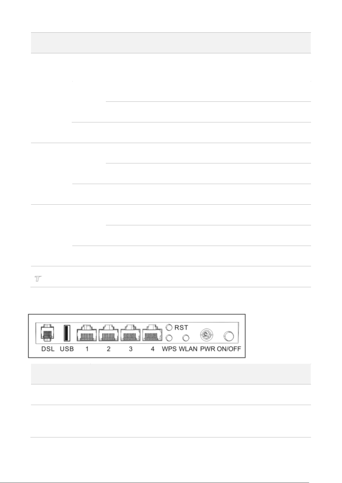
1.3.2 Ports and buttons
Button/Port
Description
ON/OFF
This button is used to turn on/off the modem router.
PWR
The power jack is used to connect to the included power adapter for power supply.
To prevent device damage, use the included power adapter for power supply.
3
Page 14
Button/Port
Description
WLAN
This button is used to enable or disable both 2.4 GHz and 5 GHz WiFi networks.
WPS
Enable the WPS function on the web UI of the modem router. Press this button for
about 3 seconds and then release it to perform the WPS negotiation process. Within 2
minutes after pressing the button, enable the wireless device’s WPS feature to
establish WPS connection.
RST
Hold down this button for about 6 seconds to restore factory settings.
1/2/3
LAN Ports. Used to connect to computers, switches, and so on.
4
WAN/LAN port. When the modem router serves as a router only, port 4 can be used as
a WAN port connected to an Ethernet jack. Otherwise, it serves as a LAN port.
USB
USBV2.0 port. Used to connect to a USB device.
Warning: The output current of the USB 2.0 port should not exceed 0.5 A.
DSL
RJ11 port. Used to connect to a phone jack for internet access.
1
2
3 4 5
6
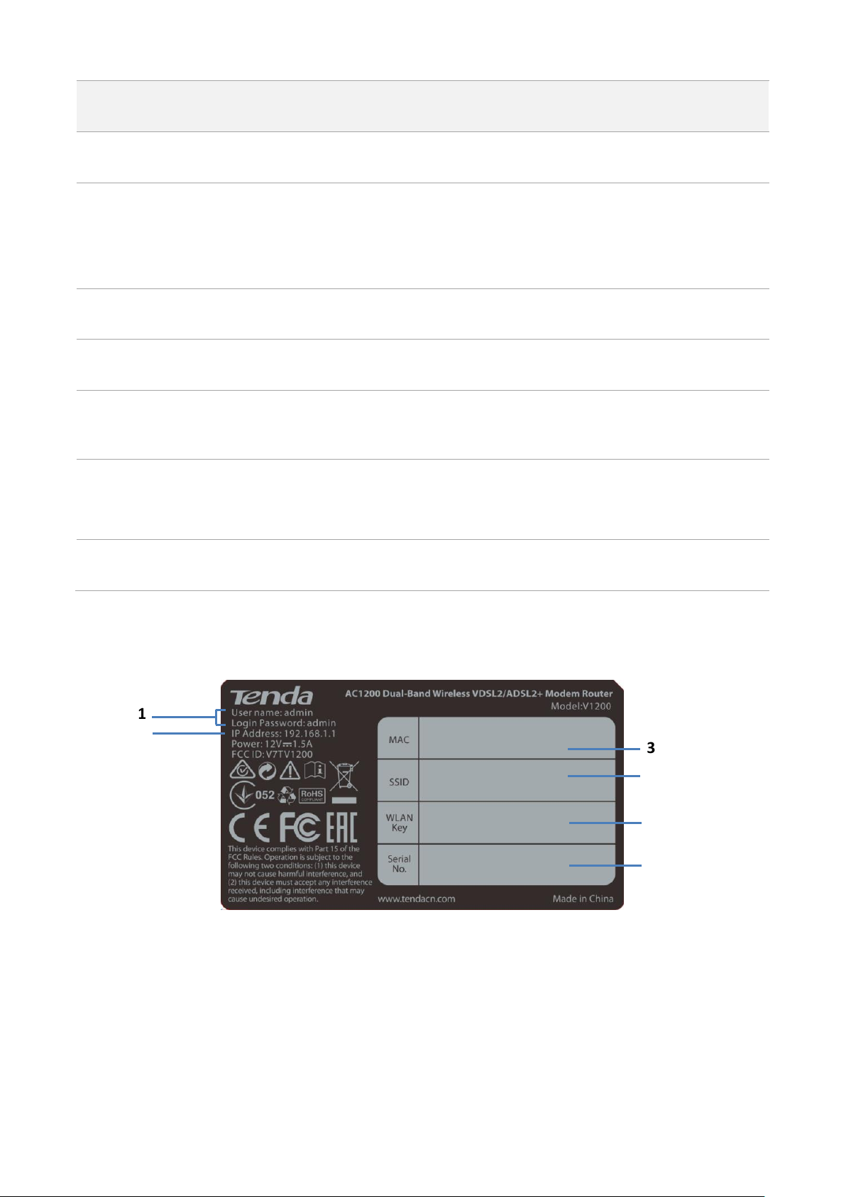
1.3.3 Label
1: Default login user name and password.
2: Default login IP address of the modem router.
3: MAC address of the modem router.
4: Default wireless network name of the modem router.
5: Default wireless password for the default wireless network.
6: The serial number of the modem router.
4
Page 15
MODEM
PHONE
LINE
2 Quick setup
2.1 Connecting the device to the internet
The modem router supports phone cable connection, Ethernet cable connection, and 3G/4G data
card. Select a connection type to follow according to your internet service.
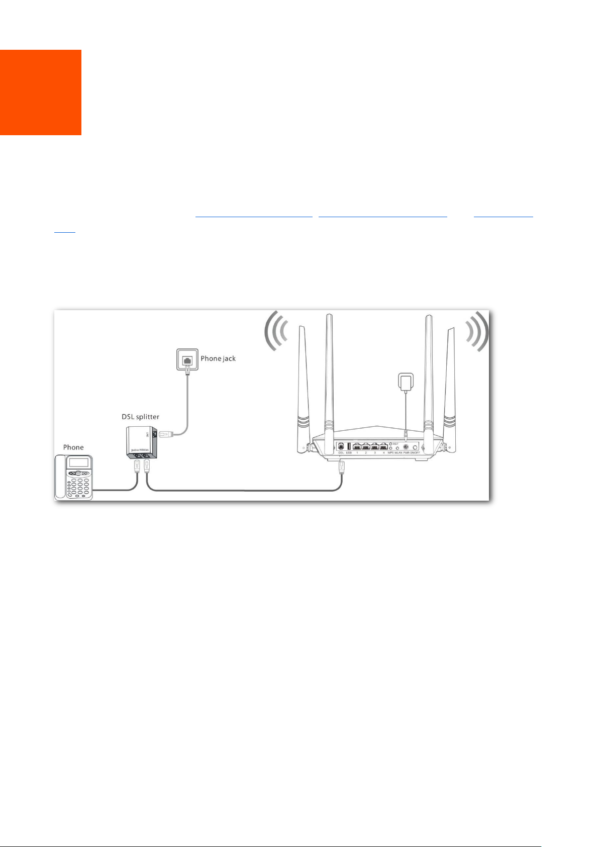
Phone cable connection
If you access the internet with a phone cable, connect the modem router as follows:
Step 1 Connect the LINE port of the included splitter to the internet.
Step 2 (Optional) If you do not need to use the phone service, skip this step. Connect the PHONE
port of the splitter to your telephone.
Step 3 Connect the MODEM port of the splitter to the DSL port of the modem router.
Step 4 Use the included power adapter to connect the modem router to a power supply.
Step 5 Turn the modem router on.
----End
5
Page 16
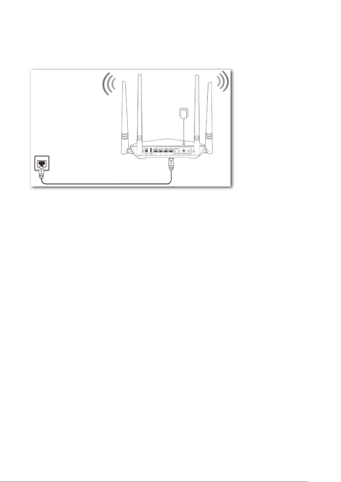
Ethernet jack
Ethernet cable connection
If you access the internet with an Ethernet cable, connect the modem router as follows:
Step 1 Connect port 4 of the modem router to the internet.
Step 2 Use the included power adapter to connect the modem router to a power supply.
Step 3 Turn the modem router on.
----End
3G/4G data card
If you access the internet with a 3G/4G dongle, perform the following steps:
Step 1 Use the included power adapter to connect the modem router to a power supply.
Step 2 Turn the modem router on.
Step 3 Insert a 3G/4G dongle provided by your ISP into USB port of the modem router for internet
access.
----End
6
Page 17

2.2 Connecting a client to the modem router
for setup
Connecting a wireless client to the modem router
Use your smart device to search and connect to the default SSID (WiFi name) of the modem router.
The default SSID is specified on the product label. This label is on the bottom of the modem router.
And by default, there is no WLAN key (WiFi password).
If either the SSID or WLAN key is changed, the wireless device is required to connect to the modem
router again.
Connecting a wired client to the modem router
Connect your computer to an available LAN port (port 1, 2, 3, or 4) of the modem router.
7
Page 18

2.3 Setting up an internet connection
2.3.1 Login
Step 1 Start a web browser on the client connected to the modem router, and visit 192.168.1.1.
Step 2 Enter the default login user name and password (both are admin), and click Login.
To prevent an unauthorized user from changing the settings of the mode router, you’d
better change the default login user name and password. Refer to Passwords for details.
----End
2.3.2 Setting up the internet settings
Select one to follow according to your internet connection type.
Phone cable connection
If you connect the modem router to the internet via a phone cable, refer to the configuration in this
part to complete your internet settings.
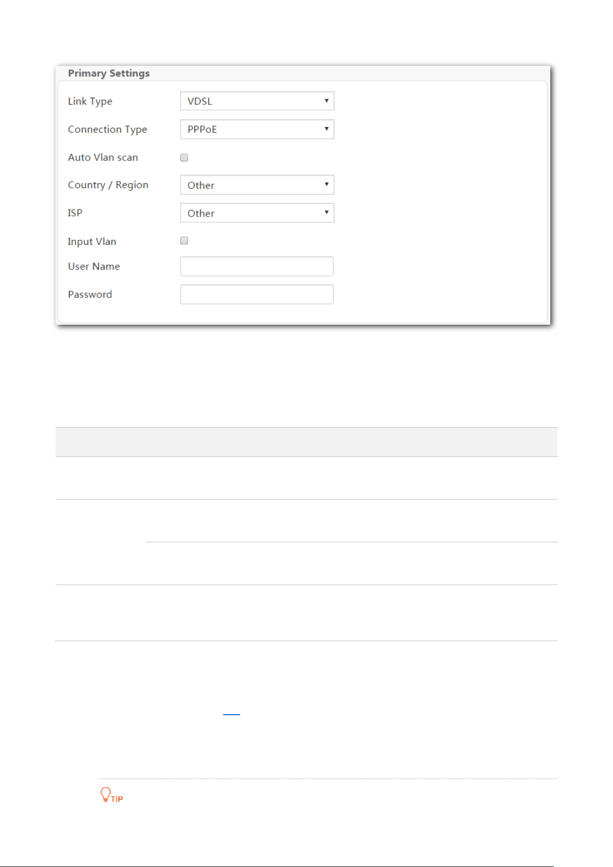
VDSL
If the link type your internet service provider (ISP) provided to you is VDSL, follow the procedure
below:
8
Page 19
Connection Type
Description
PPPoE
Select this type if your ISP provides a user name and password to you
for internet access.
IPoE
Dynamic IP
Select this type if your ISP does not provide any parameters to you for
internet access.
Static IP
Select this type if your ISP provides a static IP address and other
related information to you for internet access.
Bridge
Select this type when this device only serves as a modem, and you
want to set up a dial-up connection or enter other internet
parameters directly on your computer for internet access.
Step 1 Enter the Home page.
Step 2 Link Type: Select VDSL.
Step 3 Connection Type: Select a connection type according to the instructions in the table below,
and enter the related internet parameters.
Step 4 Auto Vlan scan: If the VLAN ID is provided, set both the Country/Region and ISP to Other,
select Input Vlan, and enter the VLAN ID in the Vlan ID box. If the VLAN ID is not provided,
select your country or region, the VLAN ID will be automatically populated. Or select Auto
Vlan scan, the modem router will try accessing the upstream device using the parameters
in the VLAN List form in A.3.
If you are uncertain about the VLAN ID, keep the default.
Step 5 Click OK on the bottom of the page to apply the settings.
9
Page 20

Connection Type
Description
PPPoE
If your ISP provides a user name and password to you for internet
access, your connection type may be PPPoE or PPPoA. Contact your
ISP for details.
PPPoA
IPoE
Dynamic IP
Select this type if your ISP does not provide any parameters to you for
internet access.
Static IP
If your ISP provides a static IP address and other related information
to you for internet access, your connection type may be IPoE or IPoA,
contact your ISP for details.
IPoA
Static IP
Bridge
Select this type when this device only serves as a modem, and you
want to set up a dial-up connection or enter other internet
parameters directly on your computer for internet access.
If you cannot access the internet after completing the primary settings, contact your ISP for
help.
----End
ADSL
If the link type your ISP provided to you is ADSL, follow the procedures below:
Step 1 Enter the Home page.
Step 2 Link Type: Select ADSL.
Step 3 Connection Type: Select a connection type according to the instructions in the table
below.
10
Page 21
Step 4 Country/Region: Select your country or region.
Step 5 ISP: Select your ISP.
Step 6 Auto PVC scan: Select your country or region from the drop-down list, and the VPI and VCI
values will be automatically populated.
If your country/region and ISP are not available in the drop-down list or the VPI and VCI
values are incorrect, select Other both from the Country/Region and ISP lists, and enter
the VPI and VCI values manually.
If you are uncertain about the VPI and VCI, select Auto PVC scan.
Step 7 Enter other internet parameters provided by your ISP (if any).
Step 8 Click OK on the bottom of the page to apply the settings.
If you cannot access the internet after completing the primary settings, contact your ISP for
help.
----End
Ethernet cable connection
If you connect the modem router to the internet with an Ethernet cable, refer to the configuration
in this part to complete your internet settings. In this case, this device only serves as a wireless
router.
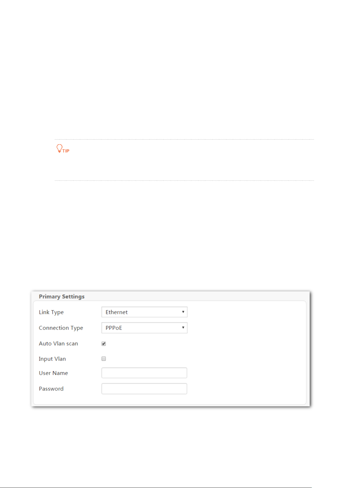
PPPoE
Use this type if you can access the internet only after setting up a dial-up connection on the
computer using a user name and password provided by your ISP.
Step 1 Enter the Home page.
Step 2 Link Type: Select Ethernet.
Step 3 Connection Type: Select PPPoE.
11
Page 22

Step 4 Auto Vlan scan: If the VLAN ID is provided, deselect Auto Vlan scan, and select your
country or region. The VLAN ID will be automatically populated. If it is incorrect, change
the value in the Vlan ID box.
If you cannot find your country or region in the drop-down list, set both the
Country/Region and ISP to Other, select input Vlan, and enter the VLAN ID in the Vlan ID
box.
If you are uncertain about the VLAN ID, keep the default.
Step 5 Enter the user name and password provided by your ISP.
Step 6 Click OK on the bottom of the page to apply the settings.
----End
If you cannot access the internet after completing the primary settings, contact your ISP for
help.
12
Page 23

IPoE
Dynamic IP
Use this type if you can access the internet without setting any information on your computer.
Step 1 Enter the Home page.
Step 2 Link Type: Select Ethernet.
Step 3 Connection Type: Select IPoE.
Step 4 Address Mode: Select Dynamic IP.
Step 5 Click OK on the bottom of the page to apply the settings.
----End
13
Page 24
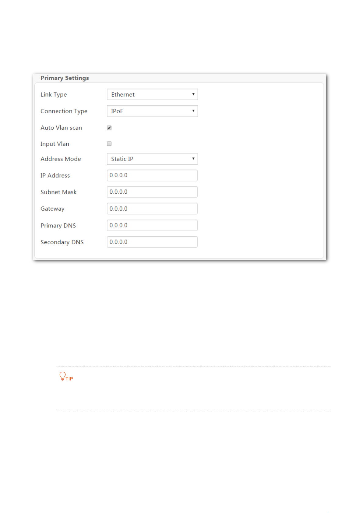
Static IP
Use this type if you can access the internet only after setting a static IP address and other related
information on your computer.
Step 1 Log in to the web UI and enter the Home page.
Step 2 Link Type: Select Ethernet.
Step 3 Connection Type: Select IPoE.
Step 4 Address Mode: Select Static IP.
Step 5 Enter the static IP address, and other related parameters.
Step 6 Click OK on the bottom of the page to apply the settings.
----End
If you cannot access the internet after completing the primary settings, contact your ISP for
help.
14
Page 25

Bridge
Select this type when this device only serves as a switch, and you want to set up a dial-up
connection or enter other internet parameters directly on your computer for internet access.
Step 1 Enter the Home page.
Step 2 Link Type: Select Ethernet.
Step 3 Connection Type: Select Bridge.
Step 4 Click OK on the bottom of the page to apply the settings.
----End
15
Page 26
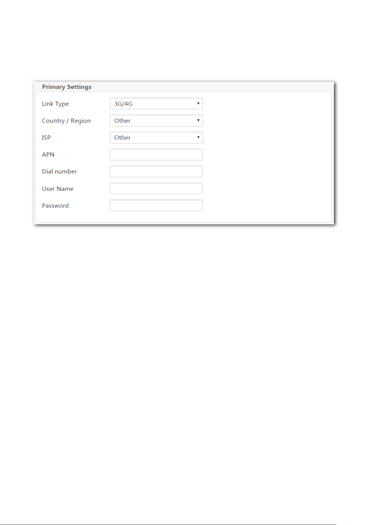
3G/4G dongle
If you connect the modem router to the internet via a 3G/4G dongle, refer to the configuration in
this part to complete your internet settings.
Step 1 Log in to the web UI and enter the Home page.
Step 2 Link Type: Select 3G/4G.
Step 3 Country / Region: Select your country or region.
Step 4 ISP: Select your ISP.
Step 5 (Optional) APN/Dial number/Username/Password: Generally, if you select a correct
country/region and ISP, the necessary parameters can be automatically filled in. If not,
enter them manually according to the internet parameters your ISP provided.
Step 6 Click OK on the bottom of the page to apply the settings.
----End
16
Page 27
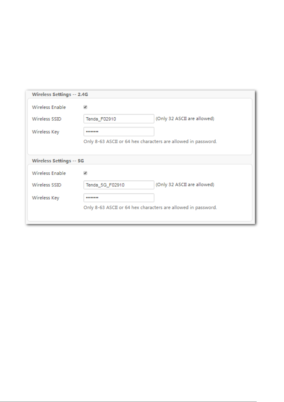
2.4 Wireless setup
The wireless feature is enabled by default. The default SSID for 2.4 GHz wireless network is
Tenda_XXXXXX, and for 5 GHz wireless network is Tenda_5G_XXXXXX, where XXXXXX is the last six
characters of the MAC address of the modem router. There is no Wireless Key (WiFi password) by
default. But there is a preset WiFi password 12345678 in the Wireless Key box for both 2.4 GHz and
5 GHz wireless networks. It takes effects when the OK button on the bottom of the page is clicked.
To customize a WiFi name and password:
Step 1 Enter the Home page.
Step 2 Wireless SSID: Enter new WiFi names for 2.4 GHz and 5 GHz wireless networks.
Step 3 Wireless Key: Enter new WiFi passwords for 2.4 GHz and 5 GHz wireless networks.
Step 4 Click OK to apply the settings.
----End
17
Page 28
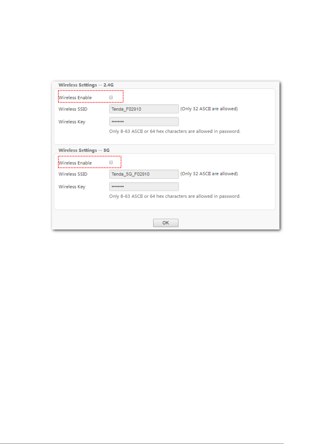
To disable wireless function:
Step 1 Enter the Home page.
Step 2 Deselect the Wireless Enable option for 2.4 GHz or 5 GHz wireless networks.
Step 3 Click OK.
----End
When the wireless feature is disabled, wireless devices cannot connect to the modem router
wirelessly.
2.5 Connecting to the modem router for
internet access
To access the internet with:
Wireless devices: connect your wireless devices to the WiFi networks of the modem router using
the SSIDs and wireless keys you set.
Wired devices: connect the wired devices to ports 1, 2, 3 or 4 (if available) of the modem router.
18
Page 29
3 Device info
3.1 Summary
Here you can view WAN status, xDSL information, and the device information.
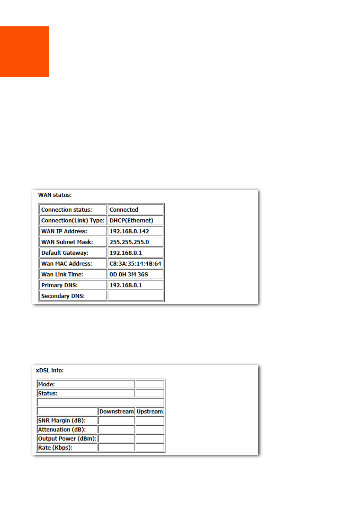
3.1.1 WAN status
If a WAN connection is established, you can check the WAN status here, including connection status,
connection type, link type, WAN IP address, gateway, WAN MAC address, WAN link time, and DNS
server information.
3.1.2 xDSL info
If an ADSL/VDSL connection is established, you can check the ADSL/VDSL connection information
here.
19
Page 30
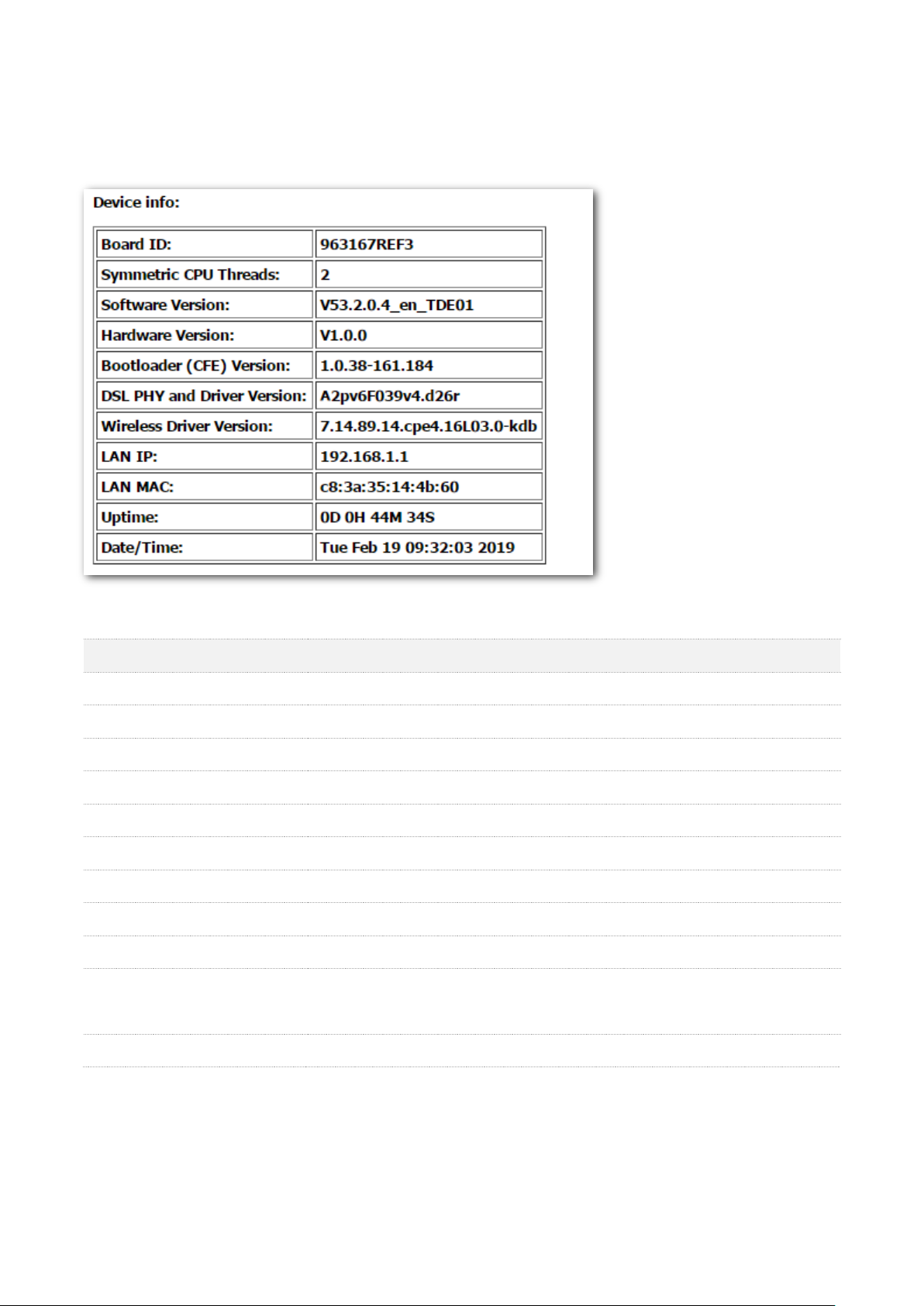
Parameter
Description
Board ID
It specifies the model of the main chip.
Symmetric CPU Threads
It specifies the number of symmetric CPU threads of the modem router.
Software Version
It specifies the software version of the modem router.
Hardware Version
It specifies the hardware version of the modem router.
Bootloader (CFE) Version
It specifies the bootloader version of the modem router.
DSL PHY and Driver Version
It specifies the DSL physic and driver version of the modem router.
Wireless Driver Version
It specifies the wireless driver version of the modem router.
LAN IP
It specifies the LAN IP address of the modem router.
LAN MAC
It specifies the LAN MAC address of the modem router.
Uptime
It specifies the total time the modem router has been running since the latest
reboot.
Date/Time
It speifies the current systemdate and time of the modem router.
3.1.3 Device info
You can check the basic information of the modem router here.
Parameter description
20
Page 31

Parameter
Description
Interface
It specifies the interface that the WAN connection uses.
Description
It specifies the description of the WAN connection.
Type
It specifies the connection type of the WAN connection.
VlanMuxId
It specifies the VLAN ID value of the WAN connection.
IPv6
It specifies the IPv6 configuration information of the WAN connection.
Igmp Pxy
It specifies whether the IGMP Multicast Proxy is enabled.
Igmp Src Enbl
It specifies whether the IGMP Multicast Source is enabled.
MLD Pxy
It specifies whether the MLD Multicast Proxy is enabled.
MLD Src Enbl
It specifies whether the MLD Multicast Source is enabled.
NAT
It specifies whether the NAT feature is enabled.
Firewall
It specifies whether firewall is enabled.
Status
It specifies the WAN connection status.
IPv4 Address
It specifies the obtained IPv4 address.
IPv6 Address
It specifies the obtained IPv6 address.
3.2 WAN
Here you can view the WAN Information including Interface, Description, Type, IGMP, NAT, Firewall,
Status, IPv4 Address and VLAN ID.
Parameter description
21
Page 32

3.3 Statistics
Here you can view the packets received and transmitted on LAN ports, WAN port, DSL port, and USB
port.
Statistics--LAN: Displays the received and transmitted packets on the LAN ports. Click Reset
Statistics to clear the current statistics.
Statistics--WAN: Displays the received and transmitted packets on the WAN port. Click Reset
Statistics to clear the current statistics.
Statistics—Interface Statistics: Displays the statistics of each interface. Click Reset to clear the
current statistics.
22
Page 33

Statistics--xDSL: Displays the received and transmitted packets on the DSL port. Click Reset
Statistics to clear the current statistics.
Statistics—3G/4G: Displays the packets received and transmitted on the USB port. Click Clear to
clear the current statistics.
23
Page 34

Parameter
Description
Destination
It specifies the destination IP address of the route.
Gateway
It specifies the gateway address of the route.
Subnet Mask
It specifies the subnet mask corresponding to the destination IP address.
Flag
It specifies the status of the corresponding route.
Metric
It specifies a number of hops the route has.
Service
It specifies the WAN connection the route uses.
Interface
It specifies the interface that the route uses.
3.4 Route
Here you can view the route table of the modem router. If the modem router fails to access the
internet, you can check the route table to find the problem.
Parameter description
24
Page 35

Parameter
Description
IP address
It specifies the IP address of the connected device.
Flags
It specifies the status of the connection between the device and the modem router.
HW Address
It specifies the MAC address of the connected device.
Device
It specifies the interface the device uses to connect to the mode router.
3.5 ARP
Here you can view the ARP list of the device. According to the information in the list, you can
identify whether there is ARP attack in your network.
Parameter description
25
Page 36

Parameter
Description
Hostname
It specifies the name of the connected device.
MAC Address
It specifies the MAC address of the connected device.
IP Address
It specifies the IP address that assigned to the connected device.
Expires In
It specifies the remaining lease time of the IP address that assigned to the connected
device.
Status
It specifies the connection type the connected device uses to connect to the modem
router.
3.6 DHCP
Here you can view the devices whose IP addresses are assigned by the DHCP server of the modem
router. You can check the IP address, MAC address and hostname of the corresponding device and
remaining lease time of the IP address.
Parameter description
26
Page 37

4 Advanced setup
4.1 Internet settings
In this module, it allows you to set up multiple internet connections or set detailed parameters for
internet access.
To set up an internet connection:
Step 1 Create an interface.
Step 2 Set up an internet connection.
This modem router provides three types of Layer2 Interface:
− ATM interface for accessing ADSL broadband internet service
− PTM interface for accessing VDSL broadband internet service
− ETH interface for connecting to the internet via an Ethernet cable
4.1.1 Setting the ATM connection
4.1.1.1 Creating an ATM interface.
Step 1 Choose Advanced Setup > Layer2 Interface > ATM Interface to enter the following page,
and click Add.
Step 2 Enter the VPI and VCI values provided by your ISP.
Step 3 Select a DSL Link Type according to the instructions in the table below, and leave other
options unchanged. Select EoA when your link type is PPPoE, IPoE, or Bridge.
Step 4 Click Apply/Save on the bottom of the page.
27
Page 38

Parameter
Description
Connection Type
PPPoE (PPP over Ethernet), PPPoA (PPP over ATM): If your ISP (ISP) provides a user
name and password to you for internet access, your connection type may be PPPoE
or PPPoA, contact your ISP for details.
IPoE (IP over Ethernet) - Dynamic IP: Select this type if your ISP does not provide
any parameters to you for internet access.
IPoE (IP over Ethernet) - Static IP, IPoA (IP over ATM) - Static IP:If your ISP provides
a static IP address and other related information to you for internet access, your
connection type may be IPoE or IPoA, contact your ISP for details.
Bridge: Select this type when this device only serves as a modem, and you want to
set up a dial-up connection or enter other internet parameters directly on your
computer for internet access.
Encapsulation Mode
It specifies the data encapsulation type in the ATM network. LLC and VC/MUX are
supported. The default is recommended.
Service Category
It specifies the ATM QoS type assigned by the ISP. The default is recommended.
----End
Parameter description
28
Page 39

Select Scheduler for
Queues of Equal
Precedence
Select the default scheduler for the queues with equal precedence.
Round Robin It assigns different weights for different kinds of packets and
provides the packets with different bandwidths based on the weights.
Weighted Fair Queuing It divides groups into different queues based on the
service streaming, IP precedence, and Hash algorithm, and fairly assigns the
bandwidth to the services with low precedence according to the weights while
ensuring the performance of services with high precedence.
Default Queue
It specifies to set up the weight of the default queue.
Default Queue
It specifies to set up the precedenceof the default queue.
Default Queue Drop
It specifies the default queue drop algorithm. It cannot be changed.
4.1.1.2 Setting up a WAN Service for the ATM Interface
PPPoE
Choose the corresponding procedure to follow according to your IP address type: IPv4 PPPoE,
IPv4&IPv6 PPPoE, and IPv6 PPPoE.
IPv4 PPPoE
Step 1 Choose Advanced Setup > WAN Service to enter the following page, and click Add.
Step 2 Select ATM interface you create on the Layer2 Interface page, which is atm0/(0_0_35) in
this example, and click Next.
29
Page 40

Step 3 Select PPP over Ethernet (PPPoE).
Step 4 Enter the 802.1P Priority and 802.1Q VLAN ID, and select the VLAN TPID according to the
VLAN parameters provided by your ISP.
Step 5 Select IPv4 Only and click Next.
Step 6 Enter the PPPoE user name and password provided by your ISP, and set other parameters
as required.
30
Page 41

Parameter
Description
PPPoE Service Name
If your ISP provides this name, enter it here. Otherwise, leave it blank.
Authentication Method
It specifies the authentication method the ISP-side uses to authenticate the
client. If you do not certain about it, select AUTO.
MAC Clone
If you can only access the internet via a specified computer, it may indicate
that your ISP binds the internet service to the MAC address of the computer
to restrict access. In this case, you need to clone the MAC address of this
computer to the modem router for internet access.
MTU
It specifies the maximum size of packet that the router can transmit. MTU
varies across connection types.
Enable Fullcone NAT
Data transmitted by a computer in LAN through the UDP port A will be
forwarded to the UDP port B in WAN. And data received by the UDP port B in
WAN will be forwarded to the UDP port A of the corresponding computer in
LAN.
Dial on demand (with idle
timeout timer)
When there is no data exchange within the specified time, the device
disconnects the connection between its WAN port and the ISP. Flow-based
charging users can select this option to save cost. Month-based charging users
do not need to select the option.
Enable Firewall
Check this option to enable the firewall of the modem router.
PPP IP extension
If this option is selected:
The NAT and firewall functions are disabled.
Only a computer in LAN can obtain the IP address which is the same as
that of the WAN port to access the internet. Other compurters cannot
obatin IP addresses to access the internet.
Use Static IPv4 Address
It is used to set up the IP address assigned by the ISP after the PPPoE dial-up
succeeds. Do not set up it if you are not a professional.
Enable PPP Debug Mode
If it is enabled, you can check the PPPoE dial-up information on the System
Log page. It is used to diagnose dial-up malfunctions.
Bridge PPPoE Frames Between
WAN and Local Ports
If it is enabled, computers in LAN can share the WAN connection for internet
access, use multiple active PPPoE accounts to access the internet (if any).
Enable IGMP Multicast Proxy
If it is enabled, the modem router can forward the multicast data to the users
in LAN. If you requires multicast applications, such as VOD or AOD, you can
Parameter description
Step 7 Leave the configuration unchanged on Routing - Default Gateway page, and click Next.
31
Page 42

Default gateway interface list can contain multiple WAN interfaces serving as system
default gateways.
Step 8 If your ISP provides you with the DNS IP addresses, select Use the following Static DNS IP
address, and enter the DNS IP addresses information. If not, select the option Select DNS
Server Interface from available WAN interfaces, and click Next.
Step 9 Check the parameters you select or set, and click Apply/Save.
32
Page 43

----End
The WAN service you set is shown on the WAN Service page.
33
Page 44

IPv4&IPv6 PPPoE
Step 1 Choose Advanced Setup > WAN Service to enter the following page, and click Add.
Step 2 Select ATM interface you create on the Layer2 Interface page, which is atm0/(0_0_35) in
this example, and click Next.
Step 3 Select PPP over Ethernet (PPPoE).
Step 4 Enter the 802.1P Priority and 802.1Q VLAN ID, and select the VLAN TPID according to the
VLAN parameters provided by your ISP.
Step 5 Select IPv4&IPv6(Dual Stack) and click Next.
34
Page 45

Parameter
Description
PPPoE Service Name
If your ISP provides this name, enter it here. Otherwise, leave it blank.
Authentication Method
It specifies the authentication method the ISP-side uses to authenticate the
client. If you do not certain about it, select AUTO.
MAC Clone
If you can only access the internet via a specified computer, it may indicate
that your ISP binds the internet service to the MAC address of the computer
to restrict access. In this case, you need to clone the MAC address of this
computer to the modem router for internet access.
MTU
It specifies the maximum size of packet that the router can transmit. MTU
varies across connection types.
Step 6 Enter the PPPoE user name and password provided by your ISP, and set other parameters
as required.
Parameter description
35
Page 46

Parameter
Description
Enable Fullcone NAT
Data transmitted by a computer in LAN through the UDP port A will be
forwarded to the UDP port B in WAN. And data received by the UDP port B in
WAN will be forwarded to the UDP port A of the corresponding computer in
LAN.
Dial on demand (with idle
timeout timer)
When there is no data exchange within the specified time, the device
disconnects the connection between its WAN port and the ISP. Flow-based
charging users can select this option to save cost. Month-based charging users
do not need to select the option.
Enable Firewall
Check this option to enable the firewall of the modem router.
PPP IP extension
If this option is selected:
The NAT and firewall functions are disabled.
Only a computer in LAN can obtain the IP address which is the same as
that of the WAN port to access the internet. Other compurters cannot
obatin IP addresses to access the internet.
Use Static IPv4 Address
It is used to set up the IPv4 IP address assigned by the ISP after the PPPoE
dial-up succeeds. Do not set up it if you are not instructed by a professional.
Use Static IPv6 Address
It is used to set up the IP address assigned by the ISP after the PPPoE dial-up
succeeds. Do not set up it if you are not instructed by a professional.
Enable IPv6 Unnumbered
Model
It is used to enable the IPv6 unnumbered model. If your ISP is not required to
select it, keep the default.
Launch Dhcp6c for Address
Assignment (IANA)
If it is enabled, the device obtains the IPv6 WAN address using the stateful
DHCPv6 type.
Launch Dhcp6c for Prefix
Delegation (IAPD)
If it is enabled, the device gets the IPv6 prefix form the DHCPv6 server, and
delivers it to its LAN ports.
Enable PPP Debug Mode
If it is enabled, you can check the PPPoE dial-up information on the System
Log page. It is used to diagnose dial-up malfunctions.
Bridge PPPoE Frames Between
WAN and Local Ports
If it is enabled, computers in LAN can share the WAN connection for internet
access, use multiple active PPPoE accounts to access the internet (if any).
Enable IGMP Multicast Proxy
If it is enabled, the modem router can forward the multicast data to the users
in LAN. If you requires multicast applications, such as VOD or AOD, you can
Enable MLD Multicast Proxy
It is used to enable the MLD multicast proxy.
Step 7 Leave the configuration unchanged on Routing - Default Gateway page, and click Next.
36
Page 47

Default gateway interface list can contain multiple WAN interfaces serving as system
default gateways.
Step 8 If your ISP provides you with the DNS IP addresses, select Use the following Static DNS IP
address/Use the following Static IPv6 DNS IP address, and enter the DNS IP addresses. If
not, select the option Select DNS Server Interface from available WAN interfaces/Obtain
IPv6 DNS info from a WAN interface, and click Next.
Step 9 Check the parameters you select or set, and click Apply/Save.
37
Page 48

----End
The WAN service you set is shown on the WAN Service page.
IPv6 PPPoE
Step 1 Choose Advanced Setup > WAN Service to enter the following page, and click Add.
Step 2 Select ATM interface you create on the Layer2 Interface page, which is atm0/(0_0_35) in
this example, and click Next.
38
Page 49

Step 3 Select PPP over Ethernet (PPPoE).
Step 4 Enter the 802.1P Priority and 802.1Q VLAN ID, and select the VLAN TPID according to the
VLAN parameters provided by your ISP.
Step 5 Select IPv6 Only and click Next.
Step 6 Enter the PPPoE user name and password provided by your ISP, and set other parameters
as required.
39
Page 50

Parameter
Description
PPPoE Service Name
If your ISP provides this name, enter it here. Otherwise, leave it blank.
Authentication Method
It specifies the authentication method the ISP-side uses to authenticate the
client. If you do not certain about it, select AUTO.
MAC Clone
If you can only access the internet via a specified computer, it may indicate
that your ISP binds the internet service to the MAC address of the computer
to restrict access. In this case, you need to clone the MAC address of this
computer to the modem router for internet access.
MTU
It specifies the maximum size of packet that the router can transmit. MTU
varies across connection types.
Enable Fullcone NAT
Data transmitted by a computer in LAN through the UDP port A will be
forwarded to the UDP port B in WAN. And data received by the UDP port B in
WAN will be forwarded to the UDP port A of the corresponding computer in
LAN.
Parameter description
40
Page 51

Parameter
Description
Dial on demand (with idle
timeout timer)
When there is no data exchange within the specified time, the device
disconnects the connection between its WAN port and the ISP. Flow-based
charging users can select this option to save cost. Month-based charging users
do not need to select the option.
Enable Firewall
Check this option to enable the firewall of the modem router.
PPP IP extension
If this option is selected:
The NAT and firewall functions are disabled.
Only a computer in LAN can obtain the IP address which is the same as
that of the WAN port to access the internet. Other compurters cannot
obatin IP addresses to access the internet.
Use Static IPv4 Address
It is used to set up the IPv4 IP address assigned by the ISP after the PPPoE
dial-up succeeds. Do not set up it if you are not instructed by a professional.
Use Static Ipv6 Address
It is used to set up the IP address assigned by the ISP after the PPPoE dial-up
succeeds. Do not set up it if you are not instructed by a professional.
Enable IPv6 Unnumbered
Model
It is used to enable the IPv6 unnumbered model. If your ISP is not required to
select it, keep the default.
Launch Dhcp6c for Address
Assignment (IANA)
If it is enabled, the device obtains the IPv6 WAN address using the stateful
DHCPv6 type.
Launch Dhcp6c for Prefix
Delegation (IAPD)
If it is enabled, the device gets the IPv6 prefix form the DHCPv6 server, and
delivers it to its LAN ports.
Enable PPP Debug Mode
If it is enabled, you can check the PPPoE dial-up information on the System
Log page. It is used to diagnose dial-up malfunctions.
Bridge PPPoE Frames Between
WAN and Local Ports
If it is enabled, computers in LAN can share the WAN connection for internet
access, use multiple active PPPoE accounts to access the internet (if any).
Enable MLD Multicast Proxy
It is used to enable the MLD multicast proxy.
Step 7 Leave the configuration unchanged on Routing - Default Gateway page, and click Next.
41
Page 52

Default gateway interface list can contain multiple WAN interfaces serving as system
default gateways.
Step 8 If your ISP provides you with the DNS IP addresses, select Use the following Static IPv6
DNS IP address, and enter the DNS IP addresses. If not, select the option Obtain IPv6 DNS
info from a WAN interface, and click Next.
Step 9 Check the parameters you select or set, and click Apply/Save.
----End
42
Page 53

The WAN service you set is shown on the WAN Service page.
IPoE
Choose the corresponding procedure to follow according to your IP address type: IPv4 IPoE,
IPv4&IPv6 IPoE, and IPv6 IPoE.
IPv4 IPoE
Step 1 Choose Advanced Setup > WAN Service to enter the following page, and click Add.
Step 2 Select ATM interface you create on the Layer2 Interface page, which is atm0/(0_0_35) in
this example, and click Next.
Step 3 Select IP over Ethernet.
Step 4 Enter the 802.1P Priority and 802.1Q VLAN ID, and select the VLAN TPID according to the
VLAN parameters provided by your ISP.
Step 5 Select IPv4 Only and click Next.
43
Page 54

Step 6 Set the WAN IP address.
− Obtain an IP address automatically: If your ISP does NOT provide you with the IP address
information, select this option.
− Use the following Static IP address: If your ISP provides you with the IP address
information, select this option and enter them.
Step 7 Set other parameters as required, and click Next.
44
Page 55

Parameter
Description
MAC Clone
If you can only access the internet via a specified computer, it may indicate
that your ISP binds the internet service to the MAC address of the computer
to restrict access. In this case, you need to clone the MAC address of this
computer to the modem router for internet access.
MTU
It specifies the maximum size of packet that the router can transmit. MTU
varies across connection types.
Option 60 Vendor ID
It is used by the client to report its manufactory and configuration
information.
Option 61 IAID
It is used to specify the IAID value of DHCP option 61 client-indentifier.
Option 61 DUID
It is used to specify the DUID value of DHCP option 61.
Option 77 User ID
It is used to specify the User ID of DHCP option 77.
Option 125
It specifies the vendor-Identifying Vendor option. If you are not instructed by
a professional, the default is recommended.
Option 50 Request IP Address
It is used to specify the request IP address of DHCP option 50.
Parameter description
45
Page 56

Parameter
Description
Option 51 Request Leased
Time
It is used to specify the request leased of DHCP option 51.
Option 54 Request Server
Address
It is used to specify the request server address of DHCP option 54.
Parameter
Description
Enable NAT
It is used to enable the NAT.
Enable Fullcone NAT
Data transmitted by a computer in LAN through the UDP port A will be
forwarded to the UDP port B in WAN. And data received by the UDP port B in
WAN will be forwarded to the UDP port A of the corresponding computer in
LAN.
Enable Firewall
Check this option to enable the firewall of the modem router.
Enable IGMP Multicast Proxy
If it is enabled, the modem router can forward the multicast data to the users
in LAN. If you requires multicast applications, such as VOD or AOD, you can
enable this option.
Step 8 Select the options as required based on the parameter description form below.
Parameter description
46
Page 57

Step 9 Leave the configuration unchanged on Routing - Default Gateway page, and click Next.
Default gateway interface list can contain multiple WAN interfaces serving as system
default gateways.
Step 10 If your ISP provides you with the DNS IP addresses, select Use the following Static DNS IP
address, and enter the DNS IP addresses information. If not, select the option Select DNS
Server Interface from available WAN interfaces, and click Next.
47
Page 58

Step 11 Check the parameters you select or set, and click Apply/Save.
----End
The WAN service you set is shown on the WAN Service page.
IPv4&IPv6 IPoE
Step 1 Choose Advanced Setup > WAN Service to enter the following page, and click Add.
Step 2 Select ATM interface you create on the Layer2 Interface page, which is atm0/(0_0_35) in
this example, and click Next.
48
Page 59

Step 3 Select IP over Ethernet.
Step 4 Enter the 802.1P Priority and 802.1Q VLAN ID, and select the VLAN TPID according to the
VLAN parameters provided by your ISP.
Step 5 Select IPv4&IPv6(Dual Stack) and click Next.
Step 6 Set the WAN IP address.
− Obtain an IP address automatically: If your ISP does NOT provide you with the IP address
information, select this option.
− Use the following Static IP address: If your ISP provides you with the IP address
information, select this option and enter them.
Step 7 Set other parameters as required, and click Next.
49
Page 60

Parameter
Description
MAC Clone
If you can only access the internet via a specified computer, it may indicate
that your ISP binds the internet service to the MAC address of the computer
to restrict access. In this case, you need to clone the MAC address of this
computer to the modem router for internet access.
MTU
It specifies the maximum size of packet that the router can transmit. MTU
varies across connection types.
Option 60 Vendor ID
It is used by the client to report its manufactory and configuration
information.
Parameter description
50
Page 61

Parameter
Description
Option 61 IAID
It is used to specify the IAID value of DHCP option 61 client-indentifier.
Option 61 DUID
It is used to specify the DUID value of DHCP option 61.
Option 77 User ID
It is used to specify the User ID of DHCP option 77.
Option 125
It specifies the vendor-Identifying Vendor option. If you are not instructed by
a professional, the default is recommended.
Option 50 Request IP Address
It is used to specify the request IP address of DHCP option 50.
Option 51 Request Leased
Time
It is used to specify the request leased of DHCP option 51.
Option 54 Request Server
Address
It is used to specify the request server address of DHCP option 54.
Obtain an IPv6 address
automatically
If your ISP does not provide you with IP address information, select this option
to obtain the IP address and other parameters from upstream device.
Dhcpv6 Address Assignment
(IANA)
If it is enabled, the device obtains the IPv6 WAN address using the stateful
DHCPv6 type.
Dhcpv6 Prefix Delegation
(IAPD)
If it is enabled, the device gets the IPv6 prefix form the DHCPv6 server, and
delivers it to its LAN ports.
Use the following Static IPv6
address
If your ISP provides you with IP address information, select this option to
enter the IP address and other parameters.
WAN Next-Hop IPv6 Address
It specifies the gateway address by default.
Step 8 Select the options as required based on the parameter description form below.
51
Page 62

Parameter
Description
Enable NAT
It is used to enable the NAT.
Enable Fullcone NAT
Data transmitted by a computer in LAN through the UDP port A will be
forwarded to the UDP port B in WAN. And data received by the UDP port B in
WAN will be forwarded to the UDP port A of the corresponding computer in
LAN.
Enable Firewall
Check this option to enable the firewall of the modem router.
Enable IGMP Multicast Proxy
If it is enabled, the modem router can forward the multicast data to the users
in LAN. If you requires multicast applications, such as VOD or AOD, you can
enable this option.
Enable MLD Multicast Proxy
It is used to enable the MLD multicast proxy.
Parameter description
52
Page 63

Step 9 Leave the configuration unchanged on Routing - Default Gateway page, and click Next.
Default gateway interface list can contain multiple WAN interfaces serving as system
default gateways.
Step 10 If your ISP provides you with the DNS IP addresses, select Use the following Static DNS IP
address/Use the following Static IPv6 DNS IP address, and enter the DNS IP addresses. If
not, select the option Select DNS Server Interface from available WAN interfaces/Obtain
IPv6 DNS info from a WAN interface, and click Next.
53
Page 64

Step 11 Check the parameters you select or set, and click Apply/Save.
----End
The WAN service you set is shown on the WAN Service page.
IPv6 IPoE
Step 1 Choose Advanced Setup > WAN Service to enter the following page, and click Add.
Step 2 Select ATM interface you create on the Layer2 Interface page, which is atm0/(0_0_35) in
this example, and click Next.
54
Page 65

Step 3 Select IP over Ethernet.
Step 4 Enter the 802.1P Priority and 802.1Q VLAN ID, and select the VLAN TPID according to the
VLAN parameters provided by your ISP.
Step 5 Select IPv6 Only and click Next.
Step 6 Set the WAN IP address.
− Obtain an IP address automatically: If your ISP does NOT provide you with the IP address
information, select this option.
− Use the following Static IP address: If your ISP provides you with the IP address
information, select this option and enter them.
Step 7 Set other parameters as required, and click Next.
55
Page 66

Parameter
Description
MAC Clone
If you can only access the internet via a specified computer, it may indicate
that your ISP binds the internet service to the MAC address of the computer
to restrict access. In this case, you need to clone the MAC address of this
computer to the modem router for internet access.
MTU
It specifies the maximum size of packet that the router can transmit. MTU
varies across connection types.
Option 60 Vendor ID
It is used by the client to report its manufactory and configuration
information.
Option 61 IAID
It is used to specify the IAID value of DHCP option 61 client-indentifier.
Option 61 DUID
It is used to specify the DUID value of DHCP option 61.
Parameter description
56
Page 67

Parameter
Description
Option 77 User ID
It is used to specify the User ID of DHCP option 77.
Option 125
It specifies the vendor-Identifying Vendor option. If you are not instructed by
a professional, the default is recommended.
Option 50 Request IP Address
It is used to specify the request IP address of DHCP option 50.
Option 51 Request Leased
Time
It is used to specify the request leased of DHCP option 51.
Option 54 Request Server
Address
It is used to specify the request server address of DHCP option 54.
Obtain an IPv6 address
automatically
If your ISP does not provide you with IP address information, select this option
to obtain the IP address and other parameters from upstream device.
Dhcpv6 Address Assignment
(IANA)
If it is enabled, the device obtains the IPv6 WAN address using the stateful
DHCPv6 type.
Dhcpv6 Prefix Delegation
(IAPD)
If it is enabled, the device gets the IPv6 prefix form the DHCPv6 server, and
delivers it to its LAN ports.
Use the following Static IPv6
address
If your ISP provides you with IP address information, select this option to
enter the IP address and other parameters.
WAN Next-Hop IPv6 Address
It specifies the gateway address by default.
Parameter
Description
Enable NAT
It is used to enable the NAT.
Enable MLD Multicast Proxy
It is used to enable the MLD multicast proxy.
Step 8 Select the options as required based on the parameter description form below.
Parameter description
Step 9 Leave the configuration unchanged on Routing - Default Gateway page, and click Next.
57
Page 68

Default gateway interface list can contain multiple WAN interfaces serving as system
default gateways.
Step 10 If your ISP provides you with the DNS IP addresses, select Use the following Static DNS IP
address/Use the following Static IPv6 DNS IP address, and enter the DNS IP addresses. If
not, select the option Select DNS Server Interface from available WAN interfaces/Obtain
IPv6 DNS info from a WAN interface, and click Next.
Step 11 Check the parameters you select or set, and click Apply/Save.
58
Page 69

----End
The WAN service you set is shown on the WAN Service page.
Bridge
Step 1 Choose Advanced Setup > WAN Service to enter the following page, and click Add.
Step 2 Select ATM interface you create on the Layer2 Interface page, which is atm0/(0_0_35) in
this example, and click Next.
59
Page 70

Step 3 Select Bridging, set other parameters as required, and click Next.
Step 4 Check the parameters you select or set, and click Apply/Save.
60
Page 71

----End
After the settings take effect, you need to set the internet settings on the devices connected to the
modem router for internet access.
61
Page 72

PPPoA (Only for internet access through phone cable)
If the DSL Link Type is set to PPPoA when you create an ATM interface, refer to the following
procedure.
Step 1 Choose Advanced Setup > WAN Service to enter the following page, and click Add.
Step 2 Select ATM interface you create on the Layer2 Interface page, which is atm0/(0_0_35) in
this example, and click Next.
Step 3 Select your internet protocol, and click Next. IPv4 is used to illustrate here.
Step 4 Enter the user name and password provided by your ISP, set other parameters as required,
62
Page 73

Parameter
Description
Authentication Method
It specifies the authentication method the ISP-side uses to authenticate the
client. If you do not certain about it, select AUTO.
Enable Fullcone NAT
Data transmitted by a computer in LAN through the UDP port A will be
forwarded to the UDP port B in WAN. And data received by the UDP port B in
WAN will be forwarded to the UDP port A of the corresponding computer in
LAN.
Dial on demand (with idle
timeout timer)
When there is no data exchange within the specified time, the device
disconnects the connection between its WAN port and the ISP. Flow-based
charging users can select this option to save cost. Month-based charging users
do not need to select the option.
Enable Firewall
Check this option to enable the firewall of the modem router.
Use Static IPv4 Address
It is used to set up the IP address assigned by the ISP after the PPPoE dial-up
succeeds. Do not set up it if you are not a professional.
Enable PPP Debug Mode
If it is enabled, you can check the PPPoE dial-up information on the System
Log page. It is used to diagnose dial-up malfunctions.
Enable IGMP Multicast Proxy
If it is enabled, the modem router can forward the multicast data to the users
in LAN. If you requires multicast applications, such as VOD or AOD, you can
and click Next.
Parameter description
Step 5 Leave the configuration unchanged on Routing - Default Gateway page, and click Next.
63
Page 74

Step 6 If your ISP provides you with the DNS IP addresses, select Use the following Static DNS IP
address, and enter the DNS IP addresses. If not, select the option Select DNS Server
Interface from available WAN interfaces, and click Next.
Step 7 Check the parameters you select or set, and click Apply/Save.
64
Page 75

----End
The WAN service you set is shown on the WAN Service page.
IPoA (Only for internet access through phone cable)
If the DSL Link Type is set to IPoA when you create an ATM interface, refer to the following
procedure.
Step 1 Choose Advanced Setup > WAN Service to enter the following page, and click Add.
Step 2 Select ATM interface you create on the Layer2 Interface page, which is atm0/(0_0_35) in
this example, and click Next.
65
Page 76

Step 3 Change the service description if required, and click Next.
Step 4 Enter the WAN IP address and subnet mask provided by your ISP, and click Next.
66
Page 77

Parameter
Description
Enable NAT
It is used to enable the NAT.
Enable Fullcone NAT
Data transmitted by a computer in LAN through the UDP port A will be
forwarded to the UDP port B in WAN. And data received by the UDP port B in
WAN will be forwarded to the UDP port A of the corresponding computer in
LAN.
Enable Firewall
Check this option to enable the firewall of the modem router.
Enable IGMP Multicast Proxy
If it is enabled, the modem router can forward the multicast data to the users
in LAN. If you requires multicast applications, such as VOD or AOD, you can
enable this option.
Step 5 Set other parameters as required, and click Next.
Parameter description
Step 6 Leave the configuration unchanged on Routing - Default Gateway page, and click Next.
Step 7 If your ISP provides you with the DNS IP addresses, select Use the following Static DNS IP
address, and enter the DNS IP addresses. If not, select the option Select DNS Server
Interface from available WAN interfaces, and click Next.
67
Page 78

Step 8 Check the parameters you select or set, and click Apply/Save.
----End
The WAN service you set is shown on the WAN Service page.
68
Page 79

Parameter
Description
Select Scheduler for Queues of
Equal Precedence
Select the default scheduler for the queues with equal precedence.
Round Robin
It specifies a QoS packet scheduling algorithm. It assigns different weights for
different kinds of packets and provides the packets with different bandwidths
based on the weights.
Weighted Fair Queuing
It specifies a QoS packet scheduling algorithm. It divides groups into different
queues based on the service streaming, IP precedence, and Hash algorithm,
and fairly assigns the bandwidth to the services with low precedence
according to the weights while ensuring the performance of services with
high precedence.
Default Queue Weight
It specifies to set up the weight of the default queue.
Default Queue Precedence
It specifies to set up the precedenceof the default queue.
Default Queue Drop Algorithm
It specifies the default queue drop algorithm. It cannot be changed.
4.1.2 Setting the PTM connection
Step 1 Create a PTM interface.
1. Choose Advanced Setup > Layer2 Interface > PTM Interface to enter the following page,
and click Add.
2. Leave the parameters for queue parameters unchanged, and click Apply/Save.
Parameter description
Step 2 Set up a WAN service for the PTM interface.
69
Page 80

1. Choose Advanced Setup > WAN Service to enter the following page, and click Add.
2. Select the interface you create in Layer2 Interface, which is ptm0/(0_1_1) in this example,
and click Next.
3. Select a WAN service type according to the instructions in the table below. Here takes
PPPoE as an example.
4. Enter the 802.1P priority and 802.1Q VLAN ID parameters provided by your ISP.
If you are unsure about the 802.1P priority and 802.1Q VLAN ID parameters, refer to
Appendix A.3 VLAN List. If the parameters are not available, ask your ISP to provide it.
5. Select your network protocol type as required, and click Next. IPv4 is used to illustrate
here. Refer to Setting up a WAN Service for the ATM Interface for the instruction of other
network protocols.
70
Page 81

Connection Type
Description
PPP over Ethernet (PPPoE)
Select this type if your ISP (ISP) provides a user name and password to you
for internet access.
IP over Ethernet
Dynamic IP
Select this type if your ISP does not provide any parameters to you for
internet access.
Static IP
Select this type if your ISP provides a static IP address and other related
information to you for internet access.
Bridging
Select this type when this device only serves as a modem, and you want to
set up a dial-up connection or enter other internet parameters directly on
your computer for internet access.
6. Enter the user name and password provided by your ISP, set other parameters as required
according to the parameter description form, and click Next.
71
Page 82

Parameter
Description
PPPoE Service Name
If your ISP provides this name, enter it here. Otherwise, leave it blank.
Authentication Method
It specifies the authentication method the ISP-side uses to authenticate the
client. If you do not certain about it, select AUTO.
MAC Clone
If you can only access the internet via a specified computer, it may indicate
that your ISP binds the internet service to the MAC address of the computer
to restrict access. In this case, you need to clone the MAC address of this
computer to the modem router for internet access.
MTU
It specifies the maximum size of packet that the router can transmit. MTU
varies across connection types.
Enable Fullcone NAT
Data transmitted by a computer in LAN through the UDP port A will be
forwarded to the UDP port B in WAN. And data received by the UDP port B in
WAN will be forwarded to the UDP port A of the corresponding computer in
LAN.
Dial on demand (with idle
timeout timer)
When there is no data exchange within the specified time, the device
disconnects the connection between its WAN port and the ISP. Flow-based
charging users can select this option to save cost. Month-based charging users
do not need to select the option.
Enable Firewall
Check this option to enable the firewall of the modem router.
Parameter description
72
Page 83

Parameter
Description
PPP IP extension
If this option is selected:
The NAT and firewall functions are disabled.
Only a computer in LAN can obtain the IP address which is the same as
that of the WAN port to access the internet. Other compurters cannot
obatin IP addresses to access the internet.
Use Static IPv4 Address
It is used to set up the IP address assigned by the ISP after the PPPoE dial-up
succeeds. Do not set up it if you are not a professional.
Enable PPP Debug Mode
If it is enabled, you can check the PPPoE dial-up information on the System
Log page. It is used to diagnose dial-up malfunctions.
Bridge PPPoE Frames Between
WAN and Local Ports
If it is enabled, computers in LAN can share the WAN connection for internet
access, use multiple active PPPoE accounts to access the internet (if any).
Enable IGMP Multicast Proxy
If it is enabled, the modem router can forward the multicast data to the users
in LAN. If you requires multicast applications, such as VOD or AOD, you can
7. Enter the PPPoE user name and password, set other parameters as required based on the
parameter description above, and click Next.
8. Leave the configuration unchanged on Routing - Default Gateway page, and click Next.
Default gateway interface list can contain multiple WAN interfaces serving as system
default gateways. The first WAN interface has the highest priority.
9. If your ISP provides you DNS IP addresses, select Use the following Static DNS IP address,
and enter the DNS IP addresses information. If not, select Select DNS Server Interface
from available WAN interfaces, and click Next
73
Page 84

10. Check the parameters you select or set, and click Apply/Save.
----End
The WAN service you set is shown on the WAN Service page.
74
Page 85

4.1.3 Setting the Ethernet connection
Step 1 Create an Ethernet interface.
1. Choose Advanced Setup > Layer2 Interface > ETH Interface to enter the following page,
and click Add.
2. Click Apply/Save.
Step 2 Set up a WAN service for the Ethernet interface.
1. Choose Advanced Setup > WAN Service to enter the following page, and click Add.
2. Select the interface you create in Layer2 Interface, which is eth3/LAN4 in this example,
and click Next.
75
Page 86

Connection Type
Description
PPP over Ethernet (PPPoE)
Select this type if your ISP provides a user name and password to you
for internet access.
IP over Ethernet
Dynamic IP
Select this type if your ISP does not provide any parameters to you for
internet access.
Static IP
Select this type if your ISP provides a static IP address and other
related information to you for internet access.
3. Select a WAN service type according to the instructions in the table below. Here takes
PPPoE as an example.
4. Select your network protocol type as required, and click Next. IPv4 is used to illustrate
here. Refer to Setting up a WAN Service for the ATM Interface for the instruction of other
network protocols.
76
Page 87

Connection Type
Description
Bridging
Select this type when this device only serves as a modem, and you
want to set up a dial-up connection or enter other internet
parameters directly on your computer for internet access.
Parameter
Description
PPPoE Service Name
If your ISP provides this name, enter it here. Otherwise, leave it blank.
Authentication Method
It specifies the authentication method the ISP-side uses to authenticate the
client. If you do not certain about it, select AUTO.
MAC Clone
If you can only access the internet via a specified computer, it may indicate
that your ISP binds the internet service to the MAC address of the computer
to restrict access. In this case, you need to clone the MAC address of this
computer to the modem router for internet access.
MTU
It specifies the maximum size of packet that the router can transmit. MTU
varies across connection types.
5. Enter the user name and password provided by your ISP, set other parameters as required
according to the parameter description form, and click Next.
Parameter description
77
Page 88

Parameter
Description
Enable Fullcone NAT
Data transmitted by a computer in LAN through the UDP port A will be
forwarded to the UDP port B in WAN. And data received by the UDP port B in
WAN will be forwarded to the UDP port A of the corresponding computer in
LAN.
Dial on demand (with idle
timeout timer)
When there is no data exchange within the specified time, the device
disconnects the connection between its WAN port and the ISP. Flow-based
charging users can select this option to save cost. Month-based charging users
do not need to select the option.
Enable Firewall
Check this option to enable the firewall of the modem router.
PPP IP extension
If this option is selected:
The NAT and firewall functions are disabled.
Only a computer in LAN can obtain the IP address which is the same as
that of the WAN port to access the internet. Other compurters cannot
obatin IP addresses to access the internet.
Use Static IPv4 Address
It is used to set up the IP address assigned by the ISP after the PPPoE dial-up
succeeds. Do not set up it if you are not a professional.
Enable PPP Debug Mode
If it is enabled, you can check the PPPoE dial-up information on the System
Log page. It is used to diagnose dial-up malfunctions.
Bridge PPPoE Frames Between
WAN and Local Ports
If it is enabled, computers in LAN can share the WAN connection for internet
access, use multiple active PPPoE accounts to access the internet (if any).
Enable IGMP Multicast Proxy
If it is enabled, the modem router can forward the multicast data to the users
in LAN. If you requires multicast applications, such as VOD or AOD, you can
6. Enter the PPPoE user name and password, set other parameters as required based on the
parameter description above, and click Next.
7. Leave the configuration unchanged, and click Next.
78
Page 89

Default gateway interface list can contain multiple WAN interfaces serving as system
default gateways. The first WAN interface has the highest priority.
8. Enter the DNS IP addresses information if they are provided by your ISP. If not, leave then
blank.
9. Click Next.
10. Check the parameters you select or set, and click Apply/Save.
----End
The WAN service you set is shown on the WAN Service page.
79
Page 90

80
Page 91

Parameter
Description
IP Address
It specifies the LAN IP address of the modem router, that is, the login address of the
web UI of the modem router.
Subnet Mask
The LAN subnet mask of the LAN port. It specifies the network segment of the LAN IP
address.
4.2 LAN
Here you can configure the LAN settings. Choose Advanced Setup > LAN to enter the configuration
page.
It allows you to modify the LAN IP of the modem router, configure the DHCP server settings, and
DNS server settings.
4.2.1 Local Area Network (LAN) Setup
4.2.1.1 Primary lan ip address
Parameter description
After the LAN IP address is changed, the computers in LAN need release their IP addresses
and obtain them again to ensure gateway of the computers is the new LAN IP address.
4.2.1.2 IGMP snooping
81
Page 92

Parameter
Description
Enable IGMP Snooping
IGMP snooping is an IPv4 layer-2 multicast constraint mechanism, which is used to
manage and control IPv4 multicast groups. If it is enabled, the specified multicast
data of IPv4 multicast groups can be forwarded to the specified LAN port.
Standard Mode
If a multicast group has no member, data of the group will be broadcast. If a
multicast group has members, data of the group will be forwarded to the LAN port
the members use.
Blocking Mode
If a multicast group has no member, data of the group will be discarded. If a
multicast group has members, data of the group will be forwarded to the LAN port
the members use.
Parameter
Description
Disable DHCP Server
If this option is selected, the DHCP server of this modem router is disabled. In this case,
this modem router does not assign IP addresses and related parameters to its clients.
Enable DHCP Server
It indicates that the modem router can assign IP addresses to connected devices.
Start IP Address: It specifies the start IP address of the IP address pool of the DHCP
server.
End IP Address: It specifies the end IP address of the IP address pool of the DHCP
server.
Enable DHCP Server
Relay
If this option is selected, the modem router works as a DHCP relay. The DHCP requests
from local computers will forward to the DHCP server runs on WAN side.
Leased Time (hour)
It specifies the validity period of one IP address assigned to a device by the modem
Parameter description
4.2.1.3 DHCP server
Parameter description
82
Page 93

Parameter
Description
router.
Primary DNS server
It specifies the primary DNS IP addresses assigned to connected devices.
Secondary DNS
server
It specifies the secondary DNS IP addresses assigned to connected devices.
Parameter
Description
Static IP Lease List
It displays a list of devices with reserved static IP addresses.
Add Entries
Click to add a static IP lease entry. A maximum 32 entries can be added.
Remove Entries
Click to remove a static IP lease entry.
4.2.1.4 DHCP reservation
Overview
Generally, IP addresses assigned by the modem router to devices are changeable. Some functions
require static device IP addresses, such as DMZ Host and virtual server. In this case you can use the
DHCP reservation function to bind IP addresses with the devices involved in the functions.
Parameter description
To bind an IP address to a specified device
Step 1 Choose Advanced Setup > LAN to enter the configuration page.
Step 2 Click Add Entries.
Step 3 Enter the MAC address of the specified device in the MAC Address box.
Step 4 Enter an IP address included in the DHCP pool of the device. Assume that the IP address of
the device is 192.168.1.1. You can enter 192.168.1.X (X ranges from 2 to 253).
Step 5 Click Apply/Save.
83
Page 94

----End
The added entry displays in the following table.
The IP address specified in the table will be always assigned to the device with the specified MAC
address in the table after the rule takes effect.
4.2.1.5 Secondary lan ip address
Overview
By default, there is only one LAN IP address for the modem router, and you can access the web UI of
the modem router by this IP address. And the modem router allows you to set up a second LAN IP
address for the modem router.
To set up a second LAN IP address
Step 1 Check the Configure the second IP Address and Subnet Mask for LAN interface option.
Step 2 Specify an IP address that belongs to a different network segment of the first IP address,
such as 192.168.2.1.
Step 3 Specify a subnet mask that fits the network segment, such as 255.255.255.0.
Step 4 Click Apply/Save.
84
Page 95

----End
The second LAN IP address can also be used to log in to the web UI of the modem router.
85
Page 96

Parameter
Description
IP Address
It specifies the IP address or IP network segment of the clients.
Max Connections
It specifies the maximum number of point-to-point connections that the modem router
can handle at the same time.
4.2.2 Connections limited
4.2.2.1 Overview
This function allows you to specify the maximum connections between the modem router and a
specified IP address or IP network segment.
Parameter description
4.2.2.2 To add a connection limited rule
Step 1 Choose Advanced Setup > LAN > Connections Limited to enter the configuration page.
Step 2 Click Add.
Step 3 Enter an IP address or an IP network segment.
Step 4 Enter the number of the maximum connections.
Step 5 Click Apply/Save.
----End
86
Page 97

4.2.3 IPv6 autoconfig
This section allows you to set up an IPv6 internet connection through auto configuration, including
the following 2 parts:
Static LAN IPv6 Address Configuration: Setting up an IPv6 global unicast address for the LAN port.
IPv6 LAN Applications: Setting up the DHCPv6 server to assign IPv6 addresses to the computers in
LAN.
Choose Advanced Setup > LAN > IPv6 Autoconfig to enter the configuration page.
4.2.3.1 Static LAN IPv6 Address Configuration
Overview
This part allows you to set up an IPv6 address for the LAN port, which is an aggregate global unicast
address.
Configuration procedure
Step 1 Choose Advanced Setup > LAN > IPv6 Autoconfig to enter the configuration page.
Step 2 Enter an IPv6 address and the prefix length.
Step 3 Click Save/Apply.
----End
87
Page 98

Parameter
Description
Enable DHCPv6
Server
It specifies whether to enable the DHCPv6 Server.
Stateless
The computers in LAN only obtain prefix and DNS information from the modem router.
The interface ID is generated based on its MAC address automatically.
The computers in LAN can visit this address to log in to the web UI of the modem router. For
example, if the address is set to 2000::1/64, enter http://[2000::1] in the address bar to access the
web UI.
4.2.3.2 IPv6 LAN Applications
The Modem router supports two IPv6 address auto-configuration types: Stateless Address Auto
Configuration and Stateful Address Auto Configuration. Select one to follow as required.
Stateless address auto configuration
Overview
The computers in LAN only obtain prefix and DNS information from the modem router. The
interface ID is generated based on its MAC address automatically.
Parameter description
88
Page 99

Parameter
Description
Enable RADVD
The RADVD (Router Advertisement Daemon) implements link-local advertisements of
IPv6 router addresses and IPv6 routing prefixes using the Neighbor Discovery Protocol
(NDP) and is used by system administrators for stateless auto configuration of network
hosts on Internet Protocol version 6 networks. Select the checkbox to enable the RADVD.
Enable ULA Prefix
Advertisement
If enabled, the modem router will advertise ULA prefix periodically. The ULA prefix can be
generated by the modem router, or be set up manually.
Randomly
Generate
If this option is selected, the ULA prefix can be automatically generated.
Statically Configure
If this option is selected, you need to manually set up the ULA prefix and validity period.
Prefix
It specifies the prefix of the IPv6 address.
Preferred Life Time
(hour)
It specifies the preferred life time in hour. When the time is out, the computer can
continue to use the address in initiated communications, but cannot use it in new
initiated communications.
Valid Life Time
(hour)
It specifies the valid life time of the IP address in hour. When the time is out, the address
is invalid.
Configuration procedure
Step 1 Choose Advanced Setup > LAN > IPv6 Autoconfig to enter the configuration page.
Step 2 Select Enable DHCPv6 Server.
Step 3 Select Stateless.
Step 4 Select Enable RADVD.
Step 5 Click Save/Apply.
----End
Stateful address auto configuration
Overview
The computers in LAN obtain all IPv6 address information from the modem router.
89
Page 100

Parameter
Description
Stateful
Stateful DHCPv6 is supported based on the assumption of prefix length less than 64.
Select this option and configure the start/end interface ID and lease time. The modem
router will automatically assign IPv6 addresses to IPv6 clients.
Start interface
ID/End interface ID
It specifies the start/end interface ID. Interface ID does NOT support ZERO COMPRESSION
"::". Please enter the complete information. For example: Please enter "0:0:0:2" instead
of "::2".
Leased Time (hour)
It specifies the validity period of one IP address assigned to a device connected to the
modem router.
Enable RADVD
The RADVD (Router Advertisement Daemon) implements link-local advertisements of
IPv6 router addresses and IPv6 routing prefixes using the Neighbor Discovery Protocol
(NDP) and is used by system administrators for stateless auto configuration of network
hosts on Internet Protocol version 6 networks. Select the checkbox to enable the RADVD.
Enable ULA Prefix
Advertisement
If enabled, the modem router will advertise ULA prefix periodically.
Randomly
Generate
If this option is selected, address prefix can be automatically generated.
Parameter description
90
 Loading...