

Page 1

Model:TWL548D
VER:3.0
Page 2
.
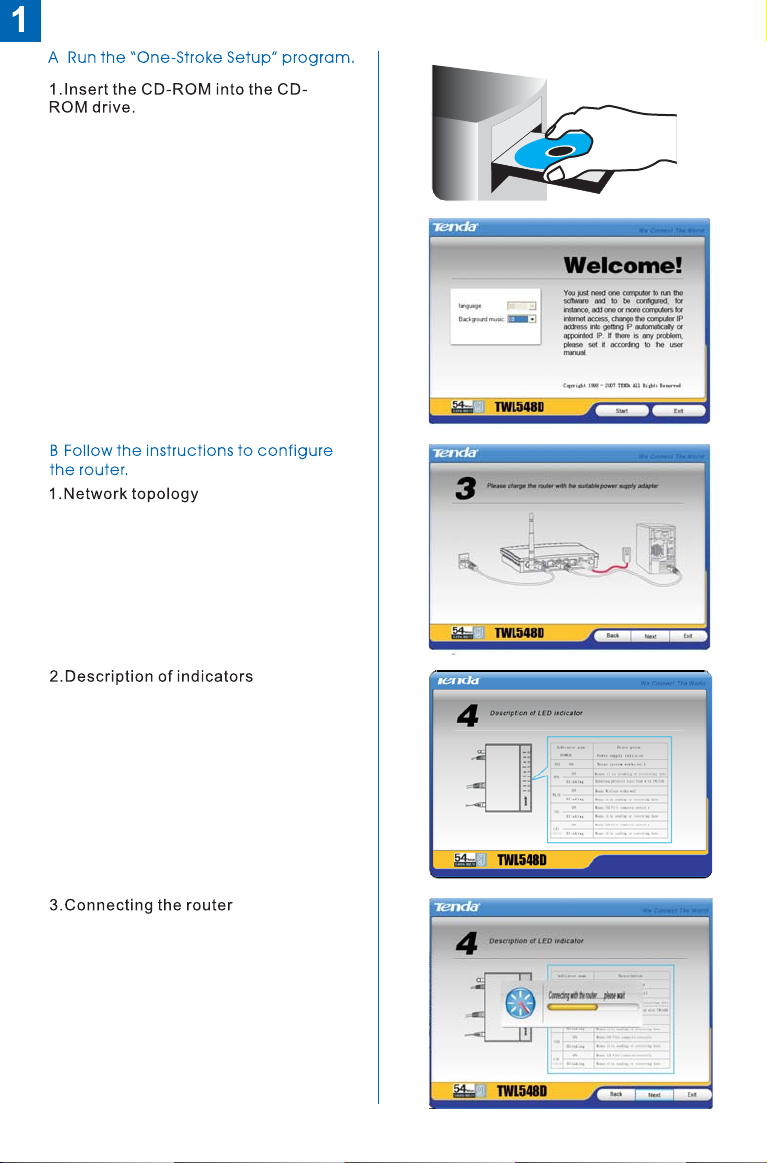
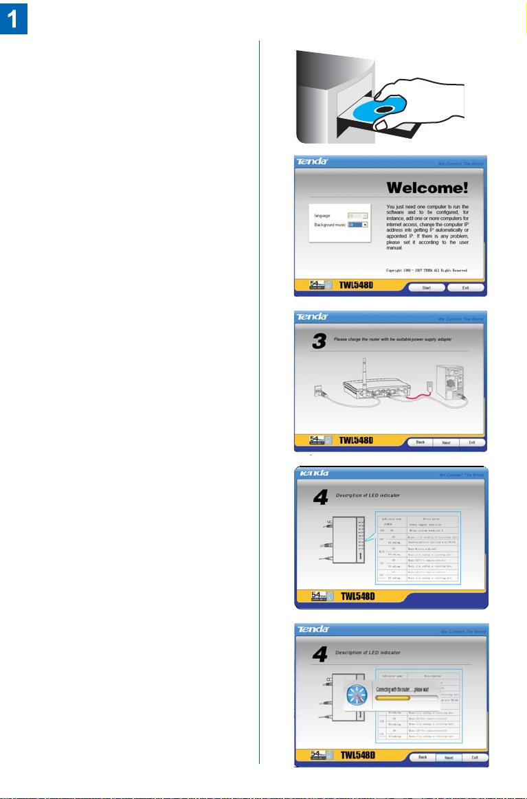
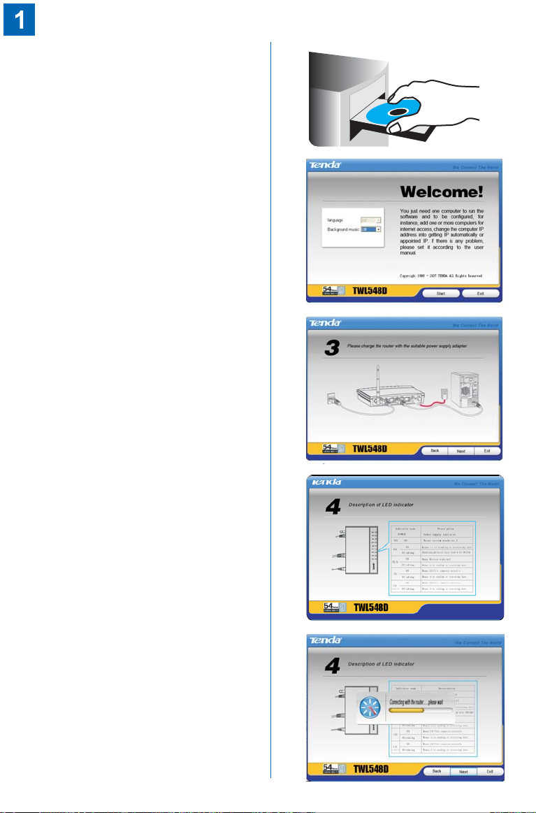
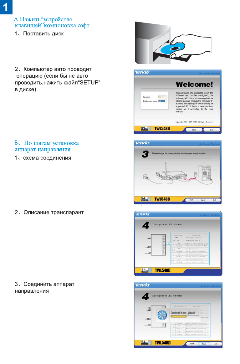
2.The setup program automatically
runs (if it does not run automatically,
double-click in the CDROM.
setup.exe
.
Page 3
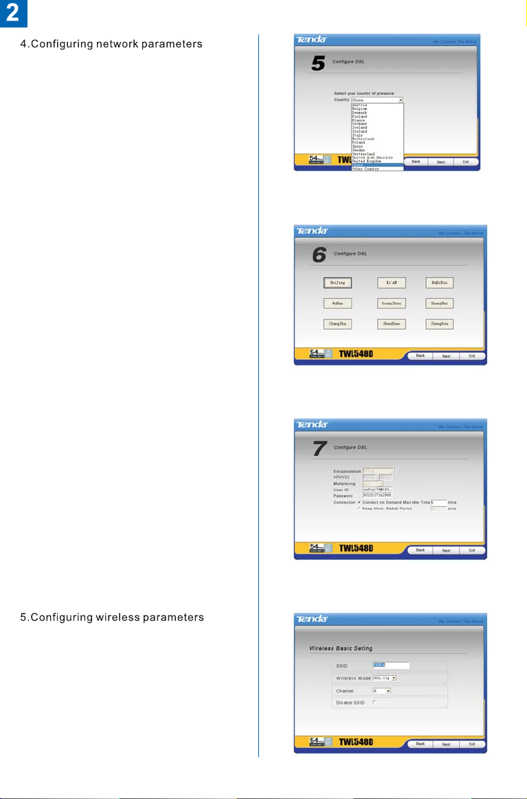
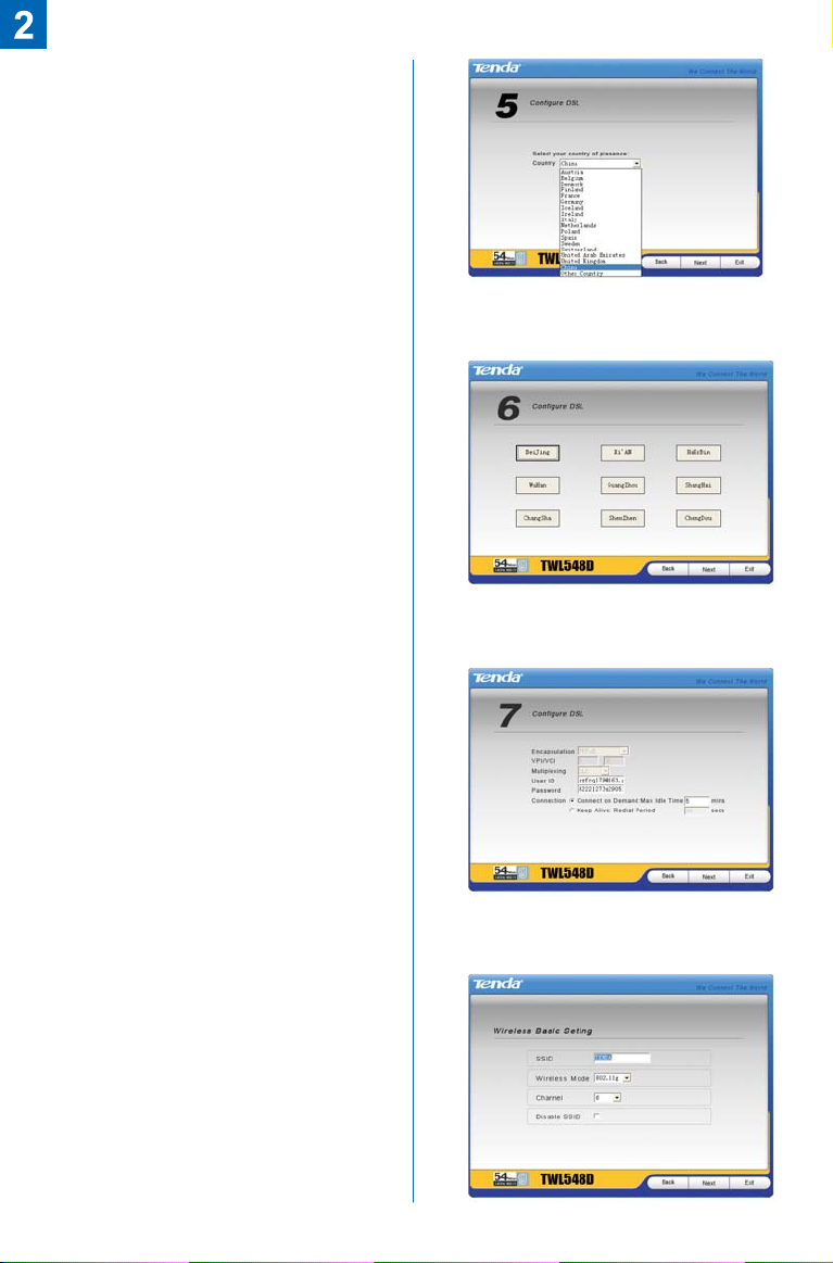
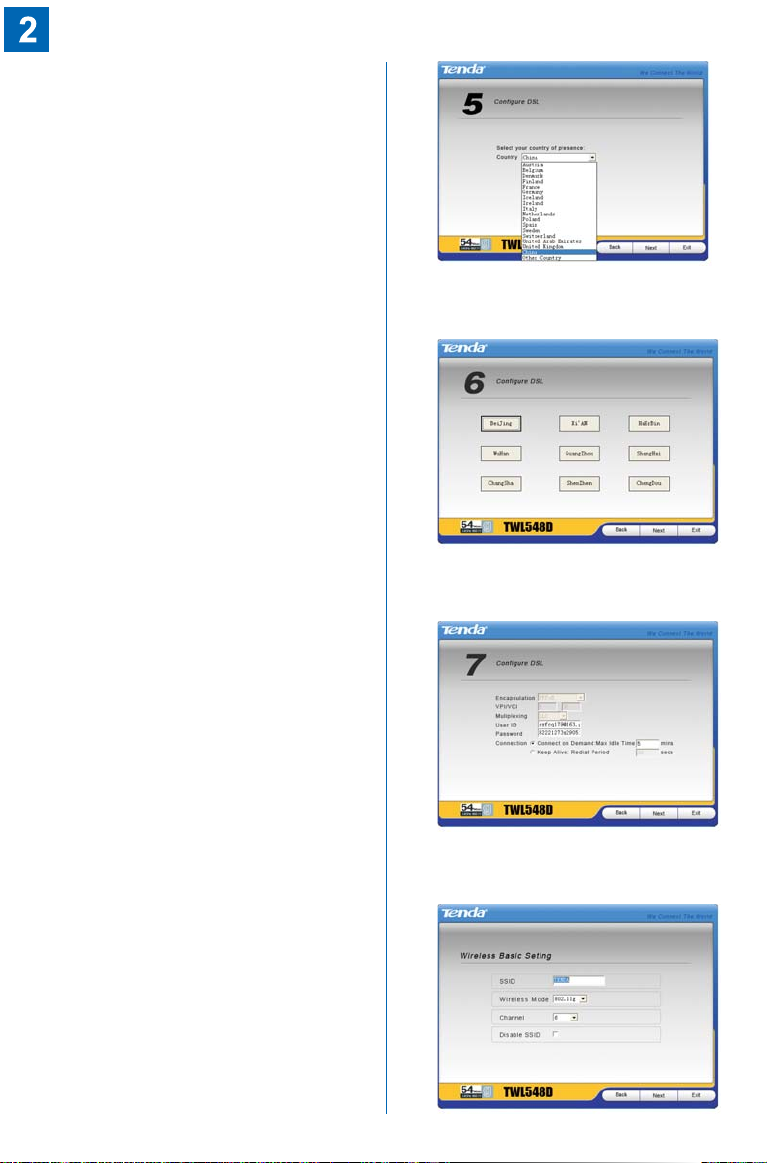
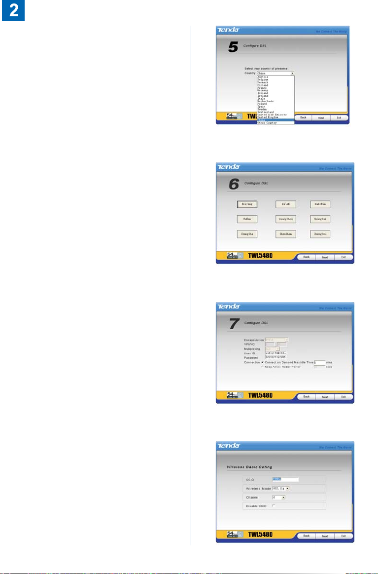
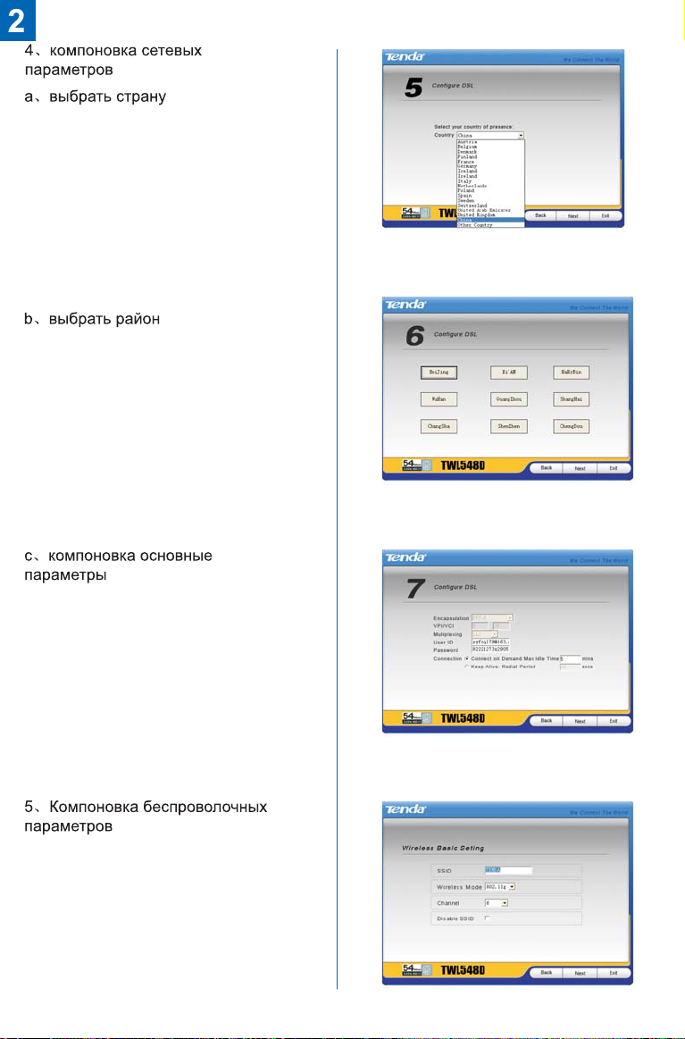
a.Select country
b. Select area
c. Configure basic parameters
Page 4
Page 5
Model:TWL548D
VER:3.0
Page 6

I . Fonctionner le logiciel de
configuration ''Faite par un Clic'’
1. Mettez le CD dedans
2.L'ordinateur fonctionne la procédure
automatiquement ( Si le fonctionnement
automatique ne commence pas, double
cliquez le fichier ''SETUP'' dans le CD)
II. Configurer le routeur pas à pas
en se jouant
1 Schéma topologique de la connexion
.
de réseau
2 Instructions à propos de l'indicateur、
3 Raccorder le routeur、
Page 7
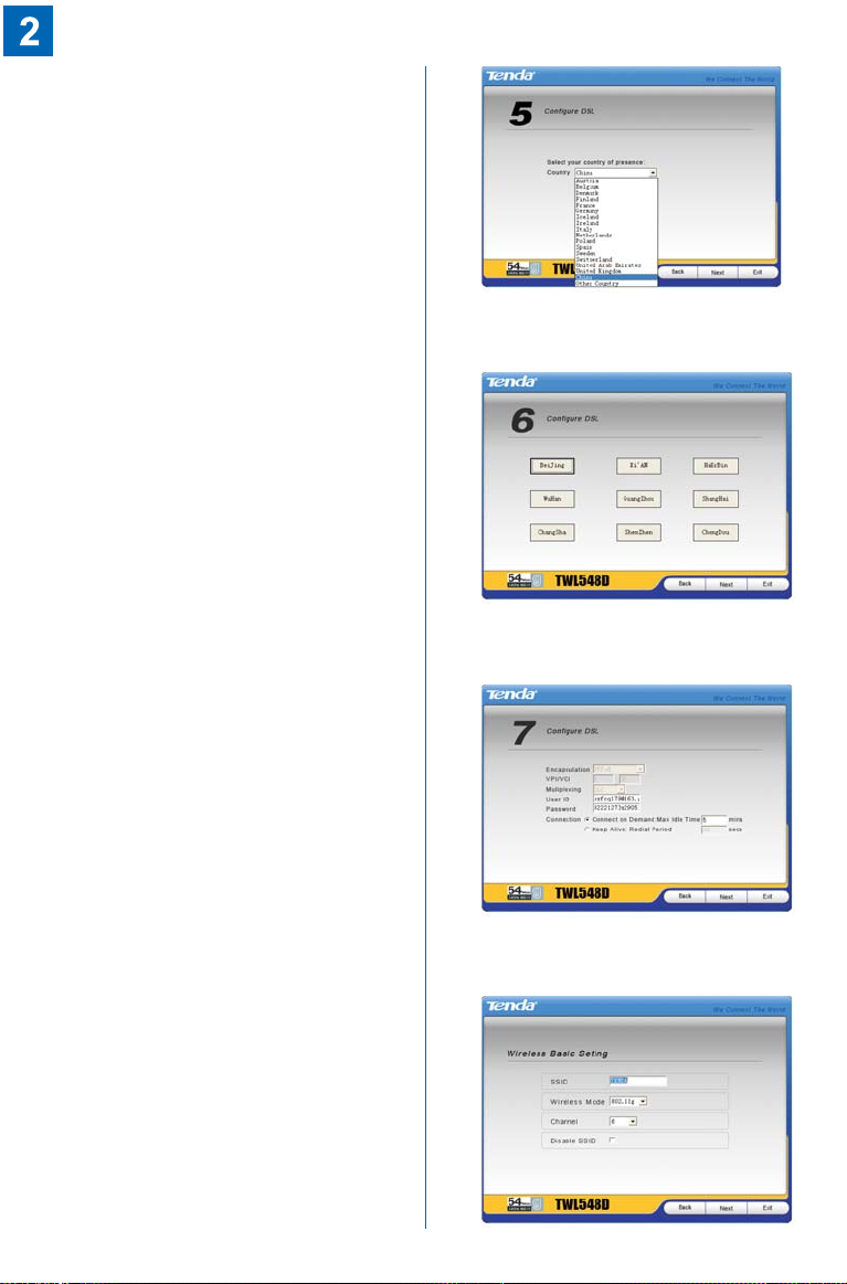
4 Configurer les paramètres de réseau、
a Choisir un pays、
b Choisir une zone、
c Configurer les paramètres de base、
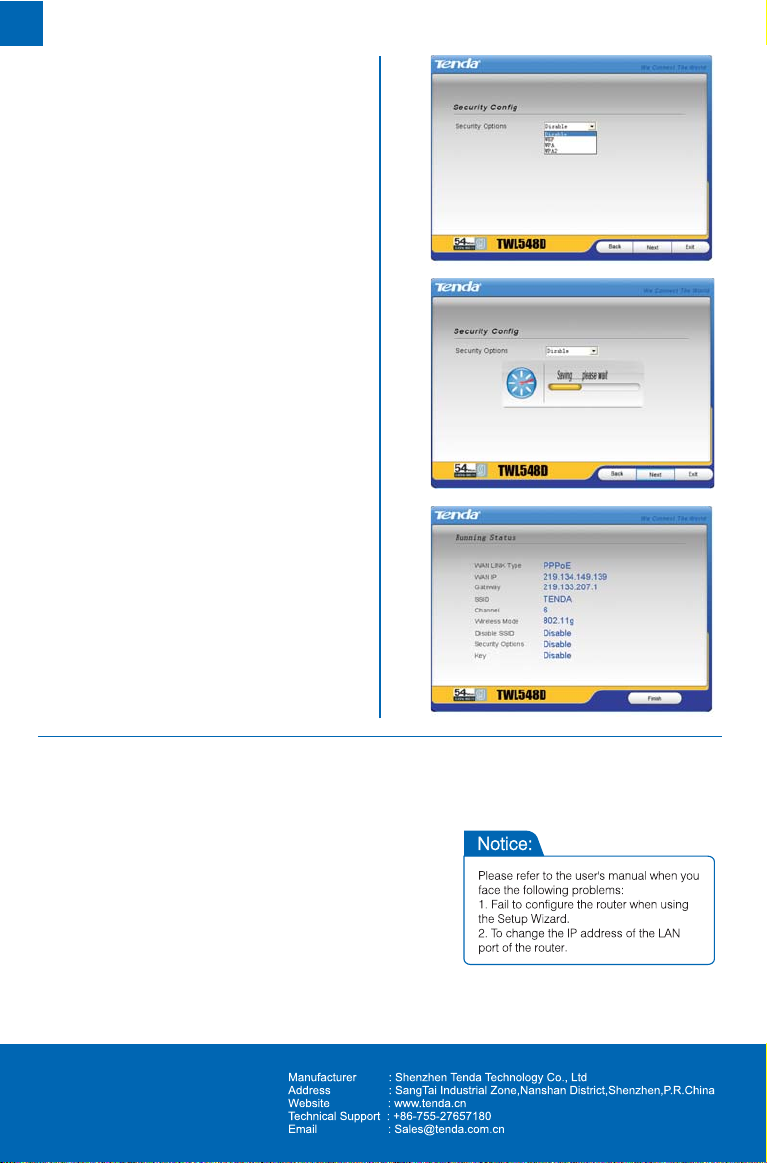
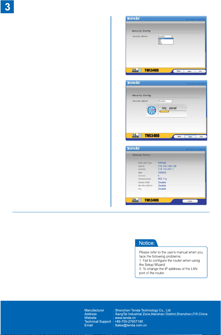
5 Configurer les paramètres sans fil、
Page 8
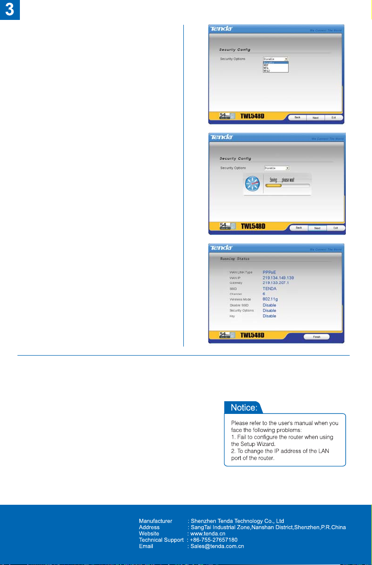
6 Configurer les paramètres de
、
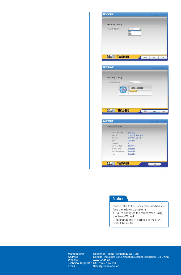
sécurité sans fil
7 Réserver et redémarrer le routeur,
、
et accomplir la configuration
8 Voir l'état de connexion de l'interface
、
de WAN et les paramètres essentiels
sans fil
Page 9
Model:TWL548D
VER:3.0
Page 10
Eins Sie laufen 1 Key Installation”
、“
Software-Konfiguration
1.Die CD in das CDROM Laufwerk
einlegen.
2. Computer läuft selbst automatisches
Programm ( wenn es nicht selbst
automatisches Programm läuft,
doppelklicken Sie die CD mit dem
„ SETUP“ Daten.)
Zwei Sie installieren leicht Internet-
、
Protokoll-Familie nach dem Schritt.
1 Verbindungsschema、
2 Die Signal-Lampe wird Angebe
、
gezeigt.
3 Internet-Protokoll-Familie Anschluss、
Page 11

4 Der Parameter des Internets wird
、
installiert.
a Select country、
b Select area、
c Configure basic parameters、
5 Installation kabelloser Parameter、
Page 12
6 Installation kabelloser und sicherer
、
Parameter
7 Speicherung und Neustart
、
Internet-Protokoll-Familie,die
Installation sind fertig.
8 Sie sehen WAN Anschluss und
、
kabelloser Parameter durch
Page 13
Model:TWL548D
VER:3.0
Page 14

A Attivare il software di configurazione
、
per “impostazione pulsante singolo”
1 Inserire il disco、
2 Il computer attiva automaticamente il
、
programma (se il programma non viene
attivato automaticamente, prego cliccare
due volte sul file “SETUP” nel disco)
B Inserire il canale in accordo
、
alle istruzioni fornite
1 Diagramma topologico della
、
connessione di rete
2 Instruzioni dell`indicatore segnale、
3 Connessione del canale、
Page 15
4 Parametri di configurazione rete、
a Selezionare un paese、
b Selezionare un distretto、
c Configurare i parametri base、
5 Parametri di configurazione per
、
la connessione senza fili
Page 16
6 Parametri di configurazione
、
automatica per la connessione
enza fili
7 Memorizzazione ed inizializzazione del
、
canale per terminare l`impostazione
8 Visualizzazione condizione di
、
connessione della porta WAN e parametro
base di configurazione della connessione
senza fili
Page 17
Model:TWL548D
VER:3.0
Page 18

ⅠMarche el software de configuración
“ Poner con una sola tecla”.
1 Inserte el disco、
2 La computadora marchará
、
automáticamente el programa
( si no, da un toque doble en el
documento “ ” del disco.
SETUP
ⅡInstala el router con mucha
facilidad de acuerdo con los
pasos fijos.
1 Gráfico、 del enlace topológico de la
conexión del Internet
2 Sinopsis de las lámparas indicadoras、
3 Conexión del router、
Page 19
4 Puesto de los parámetros para Internet、
a Elige el país、
b Elige la zona、
c Configura los parámetros básicos、
5 Configuración de los parámetros
、
inalámbricos.
Page 20
6 Configuración de los parámetros in
、
alámbricos de la seguridad.
7 Conserve las operaciones hechos
、
y reinicie el router. Hasta aquí termina
toda la configuración.
8 Revise el estado de la conexión de
、
WAN y los básicos parámetros
inalámbricos.
Page 21
Model:TWL548D
VER:3.0
Page 22
I. Opera software instalado de
“Dispoisção com um teclado”
1. Mete disco
2. O computador automaticamente
opera programa (Se não opera
automaticamente, aperta documento
“SETUP” no disco duas vezes)
II. Instala fresadora facilmente
de acordo com processos
1 Figuara topologiade ligação、
2 Introdução de luz indicador de sinal、
3 Ligação de fresadora、
Page 23
4 Coeficiente de instalação de internete、
a Escolha país、
b Escolha zona、
c Coeficientes básicos de instalação、
5 coeficiente de instalação radiotécnica、
Page 24
6 coeficiente de instalação
、
radiotécnica de segurança
7 reserva e inicia fresadora
、
outravez,eainstalação acabou
8 examina estado de ligação de
、
WAN e coeficiente instalação
tadiotécnica básica
Page 25
Model:TWL548D
VER:3.0
Page 26
Page 27
Page 28

Page 29

Model:TWL548D
VER:3.0
Page 30
A Instellen met “een knop
、
instellen” software
1 Plaats de CD in de CD-station、
2 Het installatieproces start
automatisc.(als het niet auto
start, dubbelklik op de bestand
“SETUP”、)
B Volg de instructies gemakkelijk
、
de basisstation in te stellen
1 Tekening voor instelling van netwerk、
2 Toelichtingen voor indicatielampje、
3 Verbinding met basisstation、
Page 31

4 Instellingen van netwerkelement、
a、Select voor staat
b、Select voor het gebied
c、Instellingen van gewone parameter
5 Instellingen van Wireless element、
Page 32

6 Instellingen van Wireless beveilliging、
7 Opslaan de instellingen en herstart
、
de basisstation om de configuratie te
voltooien.
8 Controleer de status van WAN
、
verbinding en de basis configuratie
van Wireless.
Page 33

Wireless Broadband Router User’s Guide
Copyright Statement
is the registered trademark of Shenzhen Tenda
Technology Co., Ltd. Other trademark or trade name mentioned
herein are the trademark or registered trademark of the
company. Copyright of the whole product as integration,
including its accessories and software, belongs to Shenzhen
Tenda Technology Co., Ltd. Without the permission of Shenzhen
Tenda Technology Co., Ltd, individual or party is not allowed to
copy, plagiarize, imitate or translate it into other languages.
All the photos and product specifications mentioned in this
manual are for references only, as the upgrading of software and
hardware, there will be changes. And if there are changes,
Tenda is not responsible for informing in advance. If you
want to know more about our products information, please
visit our website at www.tenda.cn
Page 34

Wireless Broadband Router User’s Guide
I. Hardware Installation
1. Connection of ADSL Router
1.1 Connect one end of the telephone line to the DSL interface
of the TWL548D and the other end to the MODEM interface of
the splitter.
1.2 Use a Ethernet cable to connect the LAN interface of the
TWL548D to the NIC of the computer.
1.3 Connect the power adapter to the POWER interface of the
TWL548D.
2. USB Installation
To connect the device to the USB interface of the computer, do
the following:
2.1 Connect to the USB interface of the DSL gateway through a
USB cable.
2.2 Connect the other end of the USB cable to the USB interface
of the computer.
II. Connection with WEB Management Window
1.Correctly Implementing Network Configuration of Your Computer
Page 35

Wireless Broadband Router User’s Guide
1.1 On the desktop of your
computer, right-click “My
Network Places”, and then
select “Properties” in the
shortcut menu.
1.2 In the window that appears,
right-click “Local Area
Connection”, and then select
"Properties” in the shortcut
menu.
1.3 In the pop-up dialog box,
check “Internet Protocol
(TCP/IP)” and then click
“Properties”.
Page 36

Wireless Broadband Router User’s Guide
1.4 In the window that appears,
select “Obtain an IP address
automatically (O)” or “Use
the following IP address (S)”.
1.4.1 When “Obtain an IP address
automatically (O)” is selected,
the window is as shown in the
right figure.
1.4.2 “Use the following IP address
(S)”:
IP address: 192.168.0.XXX
(XXX ranges 2 ~ 254)
Subnet mask:
255.255.255.0
Default gateway:
192.168.0.1
DNS server: Enter the local
DNS server address (for this
address, you can consult
your ISP) or the router as the
DNS server.
At the end of the setting,
click “OK” to submit the
settings. And then click “OK”
Page 37

Wireless Broadband Router User’s Guide
in the “Local Area
Connection Properties”
window.
2.Verifying the Connection
2.1 elect
“Start→Programs→Accessories
→Command Prompt”.
2.2 According to the format shown
in the right figure, enter “Ping
192.168.0.1” and press Enter. If
the system gives the result
shown in the right figure, the
connection between your
computer and the router is
normal.
Page 38

Wireless Broadband Router User’s Guide
3. Logging in to the Router
3.1 Open the WEB browser,
and enter
“http://192.168.0.1” in the
address box, and then
press Enter.
3.2 In the pop-up login
window, enter the user
name (“admin”) and
password (“admin”), and
click “OK” (both user name
and password are “admin”
by default).
3.3 If the user name and
password entered are
correct, the browser
displays the administrator
window.
Page 39

Wireless Broadband Router User’s Guide
III. Guide to Fast Installation
Enter the fast setting window.
Select the required options in
the “Country” and “Area”
drop-down lists. If you cannot
find your country and city in
these lists, you can consult
your ISP and manually enter
the VPI and VCI values of
your area. After that, click
“Next”.
1. Configure the PPPoE:
1. 1 Select “PPP over Ethernet
(PPPoE)”.
Page 40

Wireless Broadband Router User’s Guide
1.2 Click “Next”. Enter the PPP
user name and password
provided by the ISP. If the
ISP also provides the
PPPoE service name, you
can enter the corresponding
value; otherwise, keep this
field null. Use the default
values for other options. For
their details, refer to the
description of the advanced
settings.
1.3 Click “Next” and enable the
WAN service (it is enabled
by default).
1.4 Click “Next” to display the
window listing your settings.
Page 41

Wireless Broadband Router User’s Guide
1.5 Click “Save/Reboot” to
activate your settings. The
system automatically
establishes connection in
about 2 minutes.
2. Configure the PPPoA:
2.1 Select “PPP over ATM
(PPPoA)”.
2.2 Click “Next”. Enter the
PPP user name and
password provided by the
ISP. If the ISP also
provides the PPPoA
service name, you can
enter the corresponding
value; otherwise, keep this
field null. Use the default
values for other options.
For their details, refer to
Page 42

Wireless Broadband Router User’s Guide
the description of the
advanced settings.
2.3 Click “Next” and enable
the WAN service (it is
enabled by default).
2.4 Click “Next” to display the
window listing your
settings.
2.5 Click “Save/Reboot” to
activate your settings. The
system automatically
establishes connection in
about 2 minutes.
3. Configure the MER:
Page 43

Wireless Broadband Router User’s Guide
3.1 Select “MAC Encapsulation
Routing (MER)”.
3.2 Click “Next”. If your ISP
provides the static ]IP address,
you should enter the
corresponding values in “WAN
IP Address” and “WAN Subnet
Mask”.
Page 44

Wireless Broadband Router User’s Guide
3.3 If your ISP provides the
dynamic IP address, you
should select “Obtain an
IP address automatically”.
3.4 Click “Next”. In the case of
multiple computers share
the Internet access
service, it is
recommended to enable
NAT and firewall.
Page 45

Wireless Broadband Router User’s Guide
3.5 Click “Next” to display the
window listing your
settings.
3.6 Click “Save/Reboot” to
activate your settings. The
system automatically
establishes connection in
about 2 minutes.
4. Configure the IPoA:
4.1 Select “IP over ATM
(IPoA)”.
Page 46

Wireless Broadband Router User’s Guide
4.2 Click “Next” and enter the
fixed IP address and
subnet mask.
4.3 Click “Next”. It is
recommended to enable
the NAT and firewall.
4.4 Click “Next” to display the
window listing your
settings.
Page 47

Wireless Broadband Router User’s Guide
4.5 Click “Save/Reboot” to
activate your settings.
The system automatically
establishes connection in
about 2 minutes.
IV. Configuration Description
1. Device information
1.1 Click “Device Info” and then
“Summary” to display the
“Device Info” and “DSL
Info” window.
The device information
covers:
1.1.1 Hardware version
1.1.2 Software version
1.1.3 Boot version
1.1.4 Wireless driver version
1.1.5 LAN MAC address
1.1.6 WAN MAC address
1.1.7 Running time
1.1.8 System time
Page 48

Wireless Broadband Router User’s Guide
1.2 The DSL information covers:
1.2.1 Upstream link rate
1.2.2 Downstream link rate
1.2.3 LAN IP address
1.2.4 Default gateway: In the
pure bridge mode, there is
no gateway; in other modes
such as PPPoE and
PPPoA, the gateway
address is the IP address
of the upstream device.
1.2.5 Primary DNS server: In the
PPPoA/PPPoE mode, the
DNS address is obtained
from the upstream device;
in the pure bridge mode, it
is not required to set the
DNS address; in other
modes, you can manually
enter the DNS address.
1.2.6 Secondary DNS server
1.3 Click “WAN” to display the
window shown in the right
figure.
Page 49

Wireless Broadband Router User’s Guide
1.4 Click “Route” to display the
window shown in the right
figure, displaying the
default information.
2. Advanced settings
2.1 WAN
2.1.1 Click “WAN”. If the WAN
information has been set, you can
edit or modify such information in
this window, or add new WAN
information. Caution: After
modifying/adding new information,
you need to reboot the device to
activate the setting.
1) VPI (Virtual Path
Identifier): Virtual path
between two points in the
ATM network. Its value
ranges 0 ~ 255.
2) VCI (Virtual Channel
Identifier): Virtual channel
between two points in the
ATM network. Its value
ranges 32 ~ 65535 (1 ~
31 are reserved for the
Page 50

Wireless Broadband Router User’s Guide
well-known protocols).
3) Service category:
Selecting one from five
available service
categories.
4) Enable Quality of Service
(QoS): Enabling or
disabling it.
2.1.2 You can enable the VLAN
Mux and QoS. After the
VLAN Mux is enabled, the
window shown in the right
figure is displayed. You
can modify the VLAN ID
here.
2.1.3 Caution: When you click
“Next” after enabling the VLAN
Mux, the window shown in the
right figure is displayed,
because the 802.1 VLAN flag
is supported only in the
PPPoE, MER and bridge
modes.
2.1.3.1. PPPoA mode
Page 51

Wireless Broadband Router User’s Guide
1) Select “PPP over ATM (PPPoA)”.
Encapsulation Mode: VC/MUX
LLC/ENCAPSULATION
Once you select a mode, the
system automatically changes the
encapsulation mode into the one
matching your setting. Therefore,
it is recommended to keep the
default setting unchanged.
2) Click “Next” to display the window
shown in the right figure.
a. Authentication Method:
AUTO/PAP/CHAP/MSCHAP.
Usually, “AUTO” is selected.
b. Dial on demand:
If you check this option, you need
to manually enter the timeout
time. If no flow is detected when
the timeout time is up, the device
interrupts the connection
automatically. And when a flow is
detected, the device
automatically makes dial-up
connection again.
If you disable this option, the
Page 52

Wireless Broadband Router User’s Guide
device is always in online status
until device power-off, connection
failure or other failures occur.
c. PPP IP extension:
When the integrated gateway is
connected with a computer, the IP
address obtained through the
upstream link is directly allocated
to this computer connecting with
the device. After the PPP IP
extension is enabled, you can
enable the advanced DMZ. At this
time, you need to enter your DMZ
host and subnet mask.
d. Use Static IP Address:
After this option is checked, the
device uses this IP address as
the WAB IP address and does not
need to obtain it through the
upstream link.
e. Retry PPP password on
authentication error
f. Enable PPP debugging mode.
Page 53
Wireless Broadband Router User’s Guide
3) Click “Next” to display the window
shown in the right figure.
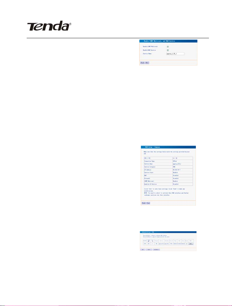
a. Enable IGMP Multicast: IGMP
agent. For example, to enable the
IPTV in the PPPoE mode, you
need to check this option.
b. Enabled WAN Service: Checked
by default. It is recommended to
keep this default setting, unless
you do not need to activate your
WAN.
4) Click “Next” to display the window
shown in the right figure. This
window lists your settings.
5) Click “Save” to display the
window shown in the right figure.
Page 54

Wireless Broadband Router User’s Guide
6) Click “Save/Reboot” to activate
your settings.
2.1.3.2. PPPoE mode
1) Select “PPP over Ethernet
(PPPoE)”.
Encapsulation Mode: VC/MUX
LLC/SNAP-BRIDGING
Once you select a mode, the
system automatically changes
the encapsulation mode into the
one matching your setting.
Therefore, it is recommended to
keep the default setting
unchanged.
Page 55

Wireless Broadband Router User’s Guide
2) Click “Next” to display the window
shown in the right figure.
a. Authentication Method:
AUTO/PAP/CHAP/MSCHAP.
Usually, “AUTO” is selected.
b. Dial on demand:
If you check this option, you
need to manually enter the
timeout time. If no flow is
detected when the timeout time
is up, the device interrupts the
connection automatically. And
when a flow is detected, the
device automatically makes
dial-up connection again.
If you disable this option, the
device is always in online status
until device power-off,
connection failure or other
failures occur.
c. PPP IP extension:
When the device is connected
with a computer, the IP address
obtained through the upstream
link is directly allocated to this
Page 56

Wireless Broadband Router User’s Guide
computer connecting with the
device. After the PPP IP
extension is enabled, you can
enable the advanced DMZ. At
this time, you need to enter your
DMZ host and subnet mask.
d. Use Static IP Address:
After this option is checked, the
device uses this IP address as
the WAB IP address and does
not need to obtain it through the
upstream link.
e. Retry PPP password on
authentication error
f. Enable PPP debugging mode.
3) Click “Next” to display the
window shown in the right figure.
a. Enable IGMP Multicast: IGMP
agent. For example, to enable the
IPTV in the PPPoE mode, you need
to check this option.
b. Enabled WAN Service: Checked
by default. It is recommended to keep
this default setting, unless you do not
need to activate your WAN.
Page 57

Wireless Broadband Router User’s Guide
4) Click “Next” to display the
window shown in the right figure.
This window lists your settings.
5) Click “Save” to display the
window shown in the right figure.
6) Click “Save/Reboot” to activate
your settings.
2.1.3.3. MER mode
1) Select “MAC Encapsulation
Routing(MER)”.
Encapsulation Mode: VC/MUX
LLC/SNAP-BRIDGING
Once you select a mode, the
system automatically changes
the encapsulation mode into the
one matching your setting.
Therefore, it is recommended to
keep the default setting
unchanged.
Page 58

Wireless Broadband Router User’s Guide
2) Click “Next” to display the
window shown in the right
figure.
a. Obtain an IP address
automatically:
If your device automatically
obtains the IP address, the
DHCP client mode is enabled
already.
b. Use the following IP address:
To manually specify an address,
you need to check this option
and enter your static IP address
and subnet mask.
c. Advanced DMZ:
Enter the IP address and
subnet mask for the DMZ host.
d. Obtain default gateway
automatically:
If this option is checked, the
device automatically obtains the
default gateway address from
the upstream device.
3) Use the following default
gateway:
Page 59

Wireless Broadband Router User’s Guide
To manually enter a gateway,
check this option.
a. Use IP Address:
After checking “Use the
following default gateway”, you
can enter a value here.
b. Use WAN Interface:
For the broadband access
device, you need to enter the IP
address of the downstream link
interface.
4) Obtain DNS server address
automatically:
If this option is checked, the
device automatically obtains the
DNS address.
5) Use the following DNS server
address:
To manually enter a DNS
address, check this option.
a. Primary DNS server
b. Secondary DNS server
Page 60

Wireless Broadband Router User’s Guide
6) Click “Next”.
a. Enable IGMP Multicast:
IGMP agent. For example, to
enable the IPTV in the PPPoE
mode, you need to check this
option.
b. Enable WAN Service:
Checked by default. It is
recommended to keep this
default setting, unless you do
not need to activate your WAN.
7) Click “Next” to display the
window shown in the right
figure. This window lists your
settings.
8) Click “Save” to display the
window shown in the right
figure.
9) Click “Save/Reboot” to activate
your settings.
Page 61

Wireless Broadband Router User’s Guide
2.1.3.4. IPoA mode
1) Select “IP over ATM (IPoA)”.
Encapsulation Mode: VC/MUX
LLC/SNAP-ROUTING
Once you select a mode, the
system automatically changes
the encapsulation mode into
the one matching your setting.
Therefore, it is recommended
to keep the default setting
unchanged.
2) Click “Next” to display the
window shown in the right
figure.
a. WAN IP Address:
Enter the IP address provided
by your ISP.
b. WAN Subnet Mask:
Enter the subnet mask
provided by your ISP.
c. Use the following default
gateway:
You can check this option.
d. Use IP Address:
Page 62

Wireless Broadband Router User’s Guide
Enter the IP address provided
by your ISP.
e. Use WAN Interface:
For the broadband access
device, you need to enter the
IP address of the downstream
link interface.
3) Use the following DNS server
address:
You can check this option.
a. Primary DNS server
b. Secondary DNS server
Caution: In the IPoA mode,
DHCP is not supported, so you
need to manually enter the
WAN IP address, subnet mask,
default gateway, DNS server
and other settings.
Page 63

Wireless Broadband Router User’s Guide
4) Click “Next”.
a. Enable NAT:
NAT enables multiple
computers in your LAN to use
the same WAN IP address for
Internet access. It is
recommended to check this
option.
b. Enable Firewall
It is recommended to check
this option to avoid some
attacks.
c. Enable IGMP Multicast:
IGMP agent. For example, to
enable the IPTV in the PPPoE
mode, you need to check this
option.
d. Enable WAN Service:
Checked by default. It is
recommended to keep this
default setting, unless you do
not need to activate your WAN.
Page 64

Wireless Broadband Router User’s Guide
e. Click “Next” to display the
window shown in the right
figure. This window lists your
settings.
f. Click “Save” to display the
window shown in the right
figure.
g. Click “Save/Reboot” to activate
your settings.
2.1.3.5. Bridging mode
1) Select “Bridging”.
Encapsulation Mode: VC/MUX
LLC/SNAP-BRIDGING
Once you select a mode, the
system automatically changes
the encapsulation mode into
the one matching your setting.
Therefore, it is recommended
to keep the default setting
unchanged.
Page 65

Wireless Broadband Router User’s Guide
2) Enable Bridge Service:
To select the bridge mode, you
need to check this option. By
default, this option is checked.
3) Click “Next” to display the
window shown in the right
figure. This window lists your
settings.
4) Click “Save” to display the
window shown in the right
figure.
5) Click “Save/Reboot” to activate
your settings.
2.2 LAN
Page 66

Wireless Broadband Router User’s Guide
2.2.1 IP Address: IP address used
by the router to connect to the
LAN. This option is set to
192.168.0.1 upon device
delivery. You can change it as
required.
Caution: After changing this
IP address, you need to use the
new IP address to access the
WEB management window upon
next login to the router. In
addition, you must set the default
gateway in each computer in
your LAN to this IP address, to
ensure normal Internet access.
2.2.2 Subnet Mask: Setting your
subnet mask.
2.2.3 Enable IGMP Snooping: Used
in the bridge mode.
2.2.4 Standard Mode
2.2.5 Blocking Mode
2.2.6 Configure the second IP
Address and Subnet Mask for
LAN interface
Page 67

Wireless Broadband Router User’s Guide
2.2.7 Click “Save/Reboot”.
2.3. NAT
2.3.1 Virtual server
1) Click “NAT” → “Virtual Server”
to display the window shown
in the right figure. Here, you
can add or delete your virtual
server settings.
By default, the external
networks cannot access the
IP address of your internal
network. However, if you need
such access by the external
networks (for example, you
need to set up the server or
support some special
applications), you should
enable this function to allow
the access by external
networks.
Page 68

Wireless Broadband Router User’s Guide
2) Click “Add” to display the
window shown in the right
figure.
a. Select a Service: Selecting the
service to be enabled.
b. Custom Server: Manually
entering the server name.
c. Server IP Address: LAN IP
address for the server.
Caution: After a service is selected,
the system automatically opens the
corresponding port. After you
manually entering a customized
service, you need to manually enter
the port to be opened.
d. Click “Save/Apply” to display
the service added, as shown
in the right figure.
2.3.2. Port triggering
Page 69

Wireless Broadband Router User’s Guide
1) Click “Port Triggering” to
display the window shown in
the right figure. Here, you can
add or delete your port
triggering service settings.
For some special applications,
you need to enable some
application ports. Through the
port triggering, you can enable
the automatic opening of the
ports required by applications.
2) Click “Add” to display the
window shown in the right
figure.
a. Select an application: Selecting
the name of the service to be
enabled.
b. Custom application: Manually
entering the service name.
Caution: After a service is selected,
the system automatically sets the
corresponding port. After you
manually entering a customized
service, you need to manually enter
Page 70

Wireless Broadband Router User’s Guide
the port to be triggered.
3) Click “Save/Apply” to display
the service added, as shown
in the right figure.
2.3.3 DMZ host
1) Click “DMZ Host” to display
the window shown in the right
figure.
2) DMZ Host IP Address:
Entering the LAN IP address
for the DMZ host.
Caution: Opening DMZ means to
open all ports. In this case, your
computer is totally exposed to the
public network. Be cautions to use
this function.
Click “Save/Apply” to activate the
settings.
2.3.4 ALG
1) Click “ALG” to display the
window shown in the right
figure.
Page 71

Wireless Broadband Router User’s Guide
2) SIP Enabled: Enabling or
disabling the SIP (Session
Initiation Protocol) function.
SIP is an application-layer
control protocol, used for
creating/modifying/terminating
the multimedia sessions, such
as Internet call.
Click “Save/Apply” to activate
the settings.
2.3.5 UPNP
1) Click “UPNP” to display the
window shown in the right
figure.
Page 72

Wireless Broadband Router User’s Guide
2) Enable UPnP: Enabling or
disabling the UPnP (Universal
Plug and Play) function.
UPnP is a kind of architecture
of common network
connection between the
computer and intelligent
devices/instruments. It is
especially common in the
family application. Based on
the Internet standards and
technologies (such as TCP/IP,
HTTP and XML), UPnP
enables automatic connection
and cooperation between
such devices, thus to make
more people can access the
network (especially the family
network).
Click “Save/Apply” to activate
the settings.
2.4 Security
2.4.1 IP filtering
1) Click “Security” → “IP
Filtering” to display the
Page 73

Wireless Broadband Router User’s Guide
window shown in the right
figure.
By default, all outgoing traffic
is allowed. However, you can
set IP filtering to restrict
external network access by
some computers in the
internal network.
2) Click “Add” to display the
window shown in the right
figure.
a. Filter Name: Setting the
filtering name to facilitate
identification.
b. Protocol: Selecting one from
four available protocols:
TCP/UDP; TCP; UDP; ICMP.
c. Source IP address: Entering
the internal network IP
address to be filtered.
d. Source Subnet Mask: Entering
the subnet mask
corresponding to the internal
network IP address to be
filtered.
Page 74

Wireless Broadband Router User’s Guide
e. Source Port: Entering the port
number of the internal network
IP address to be filtered.
f. Destination IP address:
Entering the external network
IP address to be filtered.
g. Destination Subnet Mask:
Entering the subnet mask
corresponding to the external
network IP address to be
filtered.
h. Destination Port: Entering the
port number of the external
network IP address to be
filtered.
Based on the above settings,
you can add your filtering
rules.
You can select your WAN
interface. However, it is
recommended to keep the
default setting unchanged.
3) Click “Save/Apply”.
Page 75

Wireless Broadband Router User’s Guide
4) Click “Incoming” to display the
window shown in the right
figure.
By default, all incoming traffic
is restricted. However, you
can set IP filtering to allow
internal network access by
some external computers.
5) Click “Add” to display the
window shown in the right
figure.
a. Filter Name: Setting the
filtering name to facilitate
identification.
b. Protocol: Selecting one from
four available protocols:
TCP/UDP; TCP; UDP; ICMP.
c. Source IP address: Entering
the external network IP
address to be filtered.
d. Source Subnet Mask: Entering
the subnet mask
corresponding to the external
network IP address to be
filtered.
Page 76

Wireless Broadband Router User’s Guide
e. Source Port: Entering the port
number of the external
network IP address to be
filtered.
f. Destination IP address:
Entering the internal network
IP address to be filtered.
g. Destination Subnet Mask:
Entering the subnet mask
corresponding to the internal
network IP address to be
filtered.
h. Destination Port: Entering the
port number of the internal
network IP address to be
filtered.
i. Based on the above settings,
you can add your filtering rules.
You can select your WAN
interface. However, it is
recommended to keep the
default setting unchanged.
Page 77

Wireless Broadband Router User’s Guide
6. Click “Save/Apply”.
2.4.2. Parent control
1) Click “Time of Day
Restriction” to display the
window shown in the right
figure.
2) Click “Add” to display the
window shown in the right
figure.
Here, you can set a specific
period to restrict Internet
access of a MAC address.
3) Click “Save/Apply”.
2.5. Routing
2.5.1 Default gateway
Page 78

Wireless Broadband Router User’s Guide
1) Click “Routing” → “Default
Gateway” to display the
window shown in the right
figure.
Enable Automatic Assigned
Default Gateway:
You can check/uncheck this
option. If you uncheck this
option, you need to manually
enter the default gateway
address and WAN service. It
is recommended to keep the
default setting unchanged.
2) Click “Save/Apply”.
2.5.2 Static route
1) Click “Static Route” to
display the window shown in
the right figure.
Here, you can add/delete
the items of the static route.
Page 79

Wireless Broadband Router User’s Guide
2) Click “Add” to display the
window shown in the right
figure.
Destination Network
Address: Entering the
network or host for static
route.
Subnet Mask: Entering the
subnet mask corresponding
to the network or host for
static route.
Use Gateway IP Address:
Entering the gateway
address to be passed by the
static route.
Use Interface: Selecting the
interface corresponding to
your connection mode.
Click “Save/Apply”.
Page 80

Wireless Broadband Router User’s Guide
3) Click “RIP” to display the
window shown in the right
figure.
Here, you can enable or
disable the global RIP mode.
To enable this mode, you can
select the version: 1; 2; both.
You can also select the
operation mode: Active;
Passive.
Click “Save/Apply”.
2.6.DNS
2.6.1 DNS server
1) Click “DNS Server” to display
the window shown in the right
figure.
2) Enable Automatic Assigned
DNS: After checking it, the
DNS settings are activated.
And the DHCP server of the
router allocates the added
DNS address to the client
submitting the request.
3) Primary DNS server: Entering
the DNS address provided by
Page 81

Wireless Broadband Router User’s Guide
the ISP.
4) Secondary DNS server: If your
ISP provides two DNS
addresses, you can enter the
other address here.
2.6.2 Dynamic DNS
1) Click “Dynamic DNS” to display
the window shown in the right
figure. Here, you can
add/delete the dynamic DNS
settings.
Dynamic DNS can make your
applied domain name
correspond to your IP address,
so that the other users only
need to remember your domain
name for accessing your
server.
Page 82

Wireless Broadband Router User’s Guide
2) Click “Add” to display the
window shown in the right
figure.
D-DNS provider: Selecting a
specific provider of dynamic
DNS.
Hostname: Domain name
applied by you.
Interface: Selecting one from
two available interface modes.
Username: Your user name
registered on the website of the
dynamic DNS provider.
Password: Password
corresponding to your user
name registered on the website
of the dynamic DNS provider.
3) Click “Save/Apply”.
Page 83

Wireless Broadband Router User’s Guide
2.7 DSL
Click “DSL” to display the window
shown in the right figure.
Here, you can enable a service as
required. By default, the system
checks the status of G.dmt, G.lite,
T1.413, ADSL2, ADSL2+,
READSL2, Bitswap and SRA
services. The device can automatically
negotiate with the upstream device.
2.8 Port mapping
2.8.1 Click “Port Mapping” to
display the window shown
in the right figure.
2.8.2 Enable virtual ports on:
Select or clear it.
Port mapping supports the
mapping from multiple ports
to PVC and bridging group.
Each group will serve as an
independent network.
Page 84

Wireless Broadband Router User’s Guide
2.8.3 Click “Add” to display the
window shown in the right
figure.
Group Name: Customizing
a name.
Select the interface to be
added into the group and
click “Add”.
To automatically add a LAN
customer to the PVC of a
new group, you need to add
the ID character string of a
DHCP provider. After
configuring the ID character
string for the DHCP
provider, the request of any
customer with the specified
provider ID (DHCP as “60”)
from the IP address from
the local DHCP server will
be rejected.
Caution: The customer
possibly obtains the IP
address of the public
network. In this case, the
Page 85

Wireless Broadband Router User’s Guide
selected interface is
removed from the existing
groups and added into a
new group.
2.8.4 Click “Save/Apply” to
activate the settings.
2.9 IPSec
2.9.1 Click “IPSec” to display the
window shown in the right
figure.
2.9.2 Click “Add New
Connection” to display the
window shown in the right
figure.
1) Remote IPSec Gateway
Address
2) Tunnel access from local IP
Page 86

Wireless Broadband Router User’s Guide
address
3) IP Address for VPN: Setting
the local VPN address
4) IP Subnet mask: Setting the
subnet mask corresponding
to the local VPN address.
5) Tunnel access from remote
IP address
6) IP Address for VPN: Setting
the remote VPN address
7) IP Subnet mask: Setting the
subnet mask corresponding
to the remote VPN address.
8) Key Exchange Method:
Auto (IKE); manual.
9) Authentication Method:
Selecting the authentication
method corresponding to
the key exchange method
selected
10) Pre-Shared Key: Setting
the password
11) Perfect Forward Secrecy:
Enable; Disable.
You can click “Show
Page 87

Wireless Broadband Router User’s Guide
Advanced Settings” to
modify advanced
parameters to mater your
connection.
Click “Save/Apply”.
2.10 Certificate
2.10.1 Click “Certificate” to display
the window shown in the
right figure. Here, you can
create/view/delete
certificates.
2.10.2 Click “Create Certificate
Request” to display the
window shown in the right
figure.
Enter the request details,
such as certificate name,
common name,
organization name,
state/province and country.
Click “Apply”.
Page 88

Wireless Broadband Router User’s Guide
2.10.3 Click “Import Certificate”
and “Important Certificate”
to display the window
shown in the right figure.
Enter your certificate name
and paste the certificate
content. Click “Apply”.
3. DHCP
3.1 Click “DHCP Server” to
display the window shown
in the right figure.
3.1.1 You can click “Disable
DHCP Server” or “Enable
DHCP Server”.
3.1.2 Start IP Address: Start
address of the DHCP
server IP pool
3.1.3 End IP Address: End
address of the DHCP
server IP pool
3.1.4 Leased Time: Validity
period of the IP address
obtained.
Click “Save”.
Page 89

Wireless Broadband Router User’s Guide
3.2 Click “DHCP Client List” to
view the list of the clients
with allocated DHCP
service.
4. WLAN
4.1 Basic settings
4.1.1 Click “WLAN” to display the
window shown in the right
figure.
1) Enable Wireless: Enabling
or disabling the wireless
feature.
2) Hide Access Point: Hiding
your access point to avoid
detection by the passive
scanning.
3) SSID: Service Set ID. It is
the network name of the
wireless signal, supporting
change.
4) Country: The device can
automatically adapt itself to
the channel frequency
specifications in each
Page 90

Wireless Broadband Router User’s Guide
country.
5) BSSID: Physical address
of wireless signals
Enable Wireless Guest
Network
6) Guest SSID: This value
should be unique and
same in the shared guest
network.
4.1.2 Click “Save/Apply”.
4.2 Security
4.2.1 Click “Security” to display
the window shown in the
right figure.
4.2.1.1 Select SSID
4.2.1.2 Network Authentication:
Open; Shared; 802.1X;
WPA; WPA-PSK; WPA2;
WPA2-PSK; Mixed
WAP/WPA2; Mixed
WPA2/WPA-PSK.
4.2.1.3 WEP Encryption:
Enabled; Disabled
Page 91

Wireless Broadband Router User’s Guide
1) After “Network
Authentication” is set
as “Shared”, the
system displays the
window shown in the
right figure.
a. Encryption Strength:
64-bit; 128-bit
b. Key description: You need
to enter 10 hexadecimal
digits or 5 ASCII characters
for 64-bit encryption keys.
You need to enter 26
hexadecimal digits or 13
ASCII characters for
128-bit encryption keys.
c. Current Network Key: Only
one key can be selected for
activation, but up to 4 keys
can be saved.
d. Network Key 1 ~ 4: Enter
the key with proper length
and within the valid
character range.
Page 92

Wireless Broadband Router User’s Guide
2) After “Network
Authentication” is set
as “802.1X”, the
system displays the
window shown in the
right figure.
a. RADIUS Server IP
Address: IP address of the
target server of 802.1X
authentication
b. RADIUS Port: Port number
of the target server of
802.1X authentication
c. RADIUS Key
d. Encryption Strength: 64-bit;
128-bit.
e. Key description: You need
to enter 10 hexadecimal
digits or 5 ASCII characters
for 64-bit encryption keys.
You need to enter 26
hexadecimal digits or 13
ASCII characters for
128-bit encryption keys.
f. Current Network Key: Only
Page 93

Wireless Broadband Router User’s Guide
one key can be selected for
activation, but up to 4 keys
can be saved.
g. Network Key 1 ~ 4: Enter
the key with proper length
and within the valid
character range.
4.2.2 After “Network
Authentication” is set
as “WPA”, the system
displays the window
shown in the right
figure.
1) WPA Group Rekey Interval:
Once this interval times
out, the key will change. If
this value is set to 0, the
key will not change.
2) RADIUS Server IP
Address: IP address of the
target server of 802.1X
authentication
3) RADIUS Port: Port number
of the target server of
802.1X authentication
Page 94

Wireless Broadband Router User’s Guide
4) RADIUS Key
5) WPA Encryption: TKIP;
AES; TKIP+AES
6) WEP Encryption: Enabled;
Disabled
4.2.3 After Network
Authentication” is set
as “WPA-PSK”, the
system displays the
window shown in the
right figure.
1) WPA Group Rekey Interval:
Once this interval times
out, the key will change. If
this value is set to 0, the
key will not change.
2) WPA Encryption: TKIP;
AES; TKIP+AES
3) WEP Encryption: Enabled;
Disabled
4) WPA Pre-Shared Key
Page 95

Wireless Broadband Router User’s Guide
4.2.4 After “Network
Authentication” is set
as “WPA2”, the system
displays the window
shown in the right
figure.
1) WPA2 Preauthentication:
Enabled; Disabled
2) Network Re-auth Interval:
Once this interval times
out, the system make
authentication again.
3) RADIUS Server IP
Address: IP address of the
target server of 802.1X
authentication
4) RADIUS Port: Port number
of the target server of
802.1X authentication
5) RADIUS Key
6) WPA Encryption: TKIP;
AES; TKIP+AES
7) WEP Encryption: Enabled;
Disabled
Page 96

Wireless Broadband Router User’s Guide
4.2.5 After “Network
Authentication” is set as
“WPA2-PSK”, the system
displays the window
shown in the right figure.
1) WPA Group Rekey
Interval: Once this
interval times out, the
key will change. If this
value is set to 0, the key
will not change.
2) WPA Encryption: TKIP;
AES; TKIP+AES
3) WEP Encryption:
Enabled; Disabled
4) WPA Pre-Shared Key
4.2.6 After “Network
Authentication” is set as
“Mixed WPA2/WPA”, the
system displays the
window shown in the
right figure.
Page 97

Wireless Broadband Router User’s Guide
1) WPA2 Preauthentication:
Enabled; Disabled
Network Re-auth Interval
2) WPA Group Rekey
Interval
3) RADIUS Server IP
Address: IP address of
the target server of
802.1X authentication
4) RADIUS Port: Port
number of the target
server of 802.1X
authentication
5) RADIUS Key
6) WPA Encryption: TKIP;
AES; TKIP+AES
7) WEP Encryption:
Enabled; Disabled
4.2.7 After “Network
Authentication” is set as
“Mixed WPA2/WPA
-PSK”, the system
displays the window
shown in the right figure.
Page 98

Wireless Broadband Router User’s Guide
1) WPA Pre-Shared Key
2) WPA Group Rekey
Interval: Once this
interval times out, the
key will change. If this
value is set to 0, the key
will not change.
3) WPA Encryption: TKIP;
AES; TKIP+AES
4) WEP Encryption:
Enabled; Disabled
4.3. MAC address filtering
4.3.1 Click “MAC Filter” to
display the window shown
in the right figure.
MAC Restrict Mode:
Disabled; Allow; Deny.
Here, you can also
add/delete items.
Page 99

Wireless Broadband Router User’s Guide
4.3.2 Click “Add” to display the
window shown in the right
figure.
MAC Address: Entering the
MAC address to be
controlled.
Click “Save/Apply”.
4.4 Wireless network bridge
4.4.1 Click “WLAN Bridge” to
display the window shown
in the right figure.
1) AP Mode: Access Point;
WLAN Bridge. The default
setting is “Access Point”.
2) Bridge Restrict: Enabling or
disabling the automatic
search for the wireless
network bridge within the
area.
WDS (Wireless Distribution
System): Enlarging your
network. However, you can
only set up the WDS link
with the device with
enabled WDS function.
Page 100

Wireless Broadband Router User’s Guide
4.5. Advanced
4.5.1 Click “Advanced” to display
the window shown in the
right figure.
4.5.2 AP Isolation: On; Off. When
you enable this function,
each wireless client
connected to this device
can form a virtual network,
which cannot access
another virtual network.
4.5.3 Band: 2.4 GHz by default
4.5.4 Channel: Auto; any channel
among set channels 1 ~ 13
4.5.5 Auto Channel Timer:
Available when “Auto” is
selected in “Channel”
4.5.6
54gTM Rate: Auto by
default. You can select
another rate.
4.5.7 Multicast Rate: Auto by
default. You can select
another rate.
4.5.8 Basic Rate: Default by
default. This device
 Loading...